Armasight COMMAND 336 HD User manual

ARMASIGHT by FLIRCOMMAND®
Thermal Imaging Bi-Ocular
USER MANUAL

2
ARMASIGHT by FLIRCOMMAND USER MANUAL
© 2018 FLIR Systems, Inc. All rights reserved worldwide. No parts of this manual, in whole or in part,
may be copied, photocopied, translated, or transmitted by any electronic medium or in machine-readable
form without the prior written permission of FLIR Systems, Inc.
Names and marks appearing on the products herein are either registered trademarks or trademarks of
FLIR Outdoor & Tactical Systems and/or its subsidiaries. All other trademarks, trade names, or company
names referenced herein are used for identification only and are the property of their respective owners.
This product is protected by patents, design patents, patents pending, or design patents pending.
If you have questions that are not covered in this manual, or need service, contact FLIR OTS customer
support for additional information prior to returning a product.
Phone:1-888-959-2259
E-mail: OTS-Support@flir.com
This documentation is subject to change without notice.
FLIR OUTDOOR & TACTICAL SYSTEMS
815 Dubuque Avenue, South San Francisco, CA 94080
Phone: 1-888-959-2259 or (650) 492-7755
Fax: 1-888-959-2260
International Phone/Fax: (650) 492-7755
E-mail: OTS-Support@flir.com
www.flir.com
EXPORT INFORMATION
Equipment described herein may require US Government authorization for export purposes. Diversion
contrary to US law is prohibited.
©2018 FLIR Systems, Inc.
Specifications are subject to change without notice, check our website: www.flir.com

3
ARMASIGHT by FLIRCOMMAND USER MANUAL
PROPER DISPOSAL OF ELECTRICAL AND ELECTRONIC EQUIPMENT (EEE)
The European Union (EU) has enacted Waste Electrical and Electronic Equipment Directive 2002/96/EC
(WEEE), which aims to prevent EEE waste from arising; to encourage reuse, recycling, and recovery of
EEE waste; and to promote environmental responsibility.
In accordance with these regulations, all EEE products labeled with the “crossed out wheeled bin” either
on the product itself or in the product literature must not be disposed of in regular rubbish bins, mixed
with regular household or other commercial waste, or by other regular municipal waste collection means.
Instead, and in order to prevent possible harm to the environment or human health, all EEE products
(including any cables that came with the product) should be responsibly discarded or recycled.
To identify a responsible disposal method where you live, please contact your local waste collection
or recycling service, your original place of purchase or product supplier, or the responsible government
authority in your area.
Business users should contact their supplier or refer to their purchase contract.
IMPORTANT INSTRUCTIONS AND NOTICES TO THE USER:
Modification of this device without the express authorization of FLIR Commercial Systems, Inc. may void
the user’s authority under FCC rules to operate this device.
Note 1: This equipment has been tested and found to comply with the limits for a Class B digital device,
pursuant to Part 15 of the FCC rules. These limits are designed to provide reasonable protection against
harmful interference in a residential installation.
This equipment generates, uses, and can radiate radio frequency energy and, if not installed and used in
accordance with the instructions, may cause harmful interference to radio communications. However,
there is no guarantee that the interference will not occur in a particular installation. If this equipment
does cause harmful interference to radio or television reception, which can be determined by turning
the equipment off and on, the user is encouraged to try to correct the interference by one or more of the
following measures:
• Reorient or relocate the receiving antenna
• Increase the separation between the equipment and receiver
• Connect the equipment into an outlet on a circuit different from
that of the receiver
• Consult the dealer or an experienced radio/television technician for help.
INDUSTRY CANADA NOTICE:
This Class B digital apparatus complies with Canadian ICES-003.
AVIS D’INDUSTRIE CANADA:
Cet appareil numérique de la classe B est conforme à la norme NMB-003 du Canada.

4
ARMASIGHT by FLIRCOMMAND USER MANUAL
LIST OF CONTENTS
TITLE PAGE
Safety Statement 5
SECTION 1. INTRODUCTION 6
1.1 General Information 6
1.2 Warranty Information and Registration 7
SECTION 2. DESCRIPTION AND DATA 8
2.1 System Description 8
2.2 Specifications 10
2.3 Standard Components 12
2.4 Optional Equipment 14
2.5 Key Features 15
SECTION 3. OPERATING INSTRUCTIONS 16
3.1 Installation and Mounting 16
3.2 Controls and Display Indications 18
3.3 Operating Procedures 26
SECTION 4. MAINTENANCE AND TROUBLESHOOTING 29
4.1 Preventive Maintenance Checks and Services 29
4.2 Operator Troubleshooting 31
4.3 Maintenance 32
APPENDIX 34
List of Spare Parts 34

5
ARMASIGHT by FLIRCOMMAND USER MANUAL
SAFETY SUMMARY
• Read and follow all instructions
• Read all warnings
• Only use the attachments/accessories specified by the manufacturer
• All service must be provided by the manufacturer
WARNING:
This product contains natural rubber latex, which may cause allergic reactions! The FDA has
reported an increase in the number of deaths associated with sensitivity to natural latex proteins. If you
are allergic to latex, learn which products contain it and strictly avoid exposure to those products.
CAUTION:
• Do not dismantle the equipment.
• Keep the equipment clean. Protect it from moisture, dramatic temperature drops, and electrical
shocks.
• DO NOT force the equipment controls past their stopping points.
• DO NOT leave the equipment activated during breaks in operation.
• DO NOT store the equipment with the batteries installed.
• Thoroughly clean and dry each item before placing them into the storage case.
CAUTION:
To prevent thermal damage to the equipment, never point it, either on or off, directly at the sun or any
other source of high intensity light that the unprotected human eye cannot tolerate (such as a welding
arc). To prevent inadvertent exposure to these types of sources, never leave the equipment with the
objective lens cap off.
NOTES:
• To avoid losing unsaved data, DO NOT remove the batteries or disconnect the external power
source while the Command is on.
• Inadvertent sun damage is not considered a defect in material or workmanship, and is therefore
not covered in the product warranty.

6
ARMASIGHT by FLIRCOMMAND USER MANUAL
SECTION 1
INTRODUCTION
1.1 GENERAL INFORMATION
The Command is the latest and most technologically-advanced family of thermal imaging bi-oculars for the
sporting, law enforcement, and military markets. The Command product line is based on the FLIR Tau 2 VOx
microbolometer core, and is composed of different models – each optimized for performance, price, and state-
of-the-art technology that is suitable for a variety of uses and missions.
The Command is a solid state, uncooled, long-wave infrared, magnified, dedicated handheld thermal imager
intended for day and nighttime missions.
The 24/7 mission capability is only one of the strengths of the Command line. The thermal imaging technology
also allows you to detect targets by cutting through snow, dust, smoke, fog, haze, and other atmospheric
obscurants. Unlike the use of laser targeting or near-infrared illumination to augment night vision equipment,
the Command thermal imager is extremely difficult to detect with other devices, as it emits no visible light or
RF energy.
The Command is available in different versions, with optical magnifications ranging from 2x to 5x. Command
series also provides up to 8x digital zoom for models based on 640x512 cores and up to 4x digital zoom for
models based on a 336x256 core.
The Command is powered by two CR123A (2×3V) batteries. The Extended Battery Pack or 6VDC/ 600mA
power source can also be used to power the Command.
The Command can be controlled by a wireless remote control.
The Command is equipped with a standard NTSC/PAL video input/output function that makes it possible to
connect to an external video display or monitor, or to record thermal images for field documentation or training
purposes. It also allows the transmission of data from one remote display to that of the Command.
The Command can be used in conjunction with other equipment such as the Digital Video Recorder that can
be mounted onto the Command’ Picatinny/ Weaver rail.
Extremely reliable and versatile, the Command is a highly useful thermal imaging system.

7
ARMASIGHT by FLIRCOMMAND USER MANUAL
1.2 WARRANTY INFORMATION AND REGISTRATION
1.2.1 WARRANTY INFORMATION
For warranty information and customer support visit www.armasight.com/customer-support
1.2.2 PRODUCT REGISTRATION
In order to validate the warranty on your product, the Customer must complete and submit FLIR Outdoor
& Tactical Systems’ PRODUCT REGISTRATION FORM on our website (www.armasight.com/customer-
support).
1.2.3 OBTAINING WARRANTY SERVICE
For service, repair or replacement, please contact:
FLIR OUTDOOR & TACTICAL SYSTEMS
815 Dubuque Avenue, South San Francisco, CA 94080
Phone: (888) 959-2259
Fax: (888) 959-2260
Int’l Phone/Fax: (650) 492-7755
OTS-Support@flir.com

8
ARMASIGHT by FLIRCOMMAND USER MANUAL
SECTION 2
DESCRIPTION AND DATA
2.1 SYSTEM DESCRIPTION
The Command consists of next primary parts: a body, a lens assembly and an eyepiece assembly. Figure
2-1 represents two versions of the equipment: one including a 50mm focal length objective lens, 75mm
focal length objective lens, and the other with a 100mm focal length objective lens.
The Command is a thermosensitive device. It senses the differences in heat emitted by objects in its field
of view, and converts the received temperature pattern into a viewable image that represents the scene
in contrasting black & white or color patterns, depending on the user’s selected image palette.
NOTE:
It is important that the Command sensor receive sufficient thermal contrast between the target
and background area, or between the different parts of a target. For example, the vast temperature
contrast between the snow and any heat target (such as an animal) makes it very easy to distinguish
the target.
The main optical-electronic components of the Command include: an objective Germanium thermal lens,
two eyepieces, a thermal-imaging camera, a display, a control card, and a button control panel.
The Command is equipped with manual eyepiece and objective lens focusing.
To accommodate individual user needs, the Command has a variety of digitally controlled options such as:
• Display Brightness
• Digital Zoom
FIGURE 2-1. COMMAND THERMAL IMAGING BI-OCULAR APPEARANCE
75mm LENS50mm LENS 100mm LENS

9
ARMASIGHT by FLIRCOMMAND USER MANUAL
• Palette Color Selection
• User-Controlled Manual Non-Uniformity Correction/ Flat-Field Correction (UCMNUC/ FFC)
• Imaging Enhancements
• Custom Settings
All Command devices are based on FLIR Tau 2 cameras that allow for improvements in overall image
quality in a wide range of dynamic thermal environments. The Command has employed special user-
adjustable imaging tools that include:
• Active Contrast Enhancement (ACE) – a digital “Contrast” correction that allows for smart
scene optimization based on dynamic adjustments, where a variety of contrast levels occur
depending on relative scene temperature.
• Second Generation Digital Detail Enhancement (DDE) – a “Sharpness” correction that
digitally enhances the picture, significantly sharpens edges, and further reduces image noise.
• Smart Scene Optimization (SSO) – a fine-tuning computational correction that significantly
improves overall visual acuity for targets that have thermal signatures similar to the surrounding
background.
• Information-Based Histogram Equalization (IBHEQ) – a “Sky/Sea” enhancement –
information-based environment dependent algorithm that automatically adjusts camera gain and
excludes pixels determined to not contain critical information. Specifically helpful in scenes with
great expanses of visible sky or water.
• User-Controlled Manual Non-Uniformity Correction/ Flat-Field Correction (UCMNUC/
FFC). There is a mechanical shutter between the camera sensor and the lens. This shutter is used
to perform a non-uniformity correction (NUC), also known as flat-field correction (FFC). During FFC,
the shutter presents a uniform temperature source to each detector element in the array. While
imaging the flat-field source, the camera updates the offset correction coefficients, resulting in a
more uniform image after the process is complete. All Command models allow for user to manually
trigger or interrupt scheduled UCMNUC/ FFC function.
• Silent Shutterless NUC™ (SSN) – In addition to User-Controlled Manual NUC/ FFC, all
Command models employ a digital, supplemental, non-mechanical flat-field correction that extends
periods between mechanical shutter events and further reduces image noise. SSN is an always
ON enhancement.
Information on the current operating state (battery status, active function in the display etc.) is
continuously displayed, making field operation of the Command simple and convenient.
Manufactured for exceptional durability, the Command has a lightweight and robust aluminum body. A
side Picatinny/ Weaver rail allows for the installation of an optional Digital Video Recorder, extended
battery pack, or other equipment.
A standard NTSC/PAL video input/ output connector enables an external video display (monitor/ TV) or
video recorder to be connected to the Command. An external 6VDC/600mA power source can also be
connected to the Command.
The Command is powered by two CR123A (2×3V) batteries.
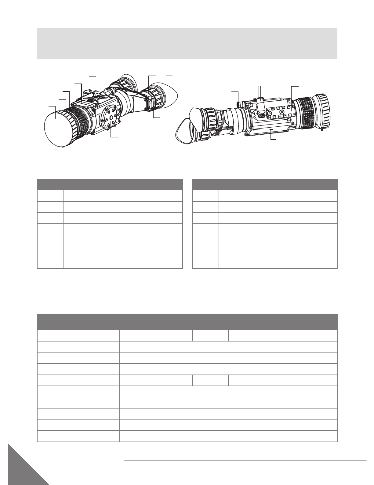
Figure 2-2 shows the Command. The ITEM NO. column of Table 2-1 indicates the number used to identify
items in Figure 2-2.

10
ARMASIGHT by FLIRCOMMAND USER MANUAL
NOTE:
Here and below, the example used is the Command with a 50mm lens.
FIGURE 2-2. COMMAND THERMAL IMAGING BI-OCULAR. SYSTEM DESCRIPTION
8
9
1
2
3
5
4
6 7
11
10 12 13
14
TABLE 2-1. SYSTEM DESCRIPTION
ITEM DESCRIPTION ITEM DESCRIPTION
1 Objective Lens Cap 8 Eyepiece
2Objective Lens 9 Battery Cap
3 Objective Focus Ring 10 Turn-Pull Switch
4Body 11 Connector Cap
5 Button Control Panel 12 Connector
6Eyepiece Focus Ring 13 Side Picatinny/Weaver Rail
7Eyecup 14 Tripod Socket
2.2 SPECIFICATIONS
TABLE 2-2. SYSTEM DATA
ITEM COMMAND
336 3-12x50
COMMAND
640 2-16x50
COMMAND
336 5-20x75
COMMAND
640 3-24x75
COMMAND
336 8-32x100
COMMAND
640 4-32x100
Magnification (NTSC/PAL) 2.8× / 3.4× 1.5× / 1.8× 5.3× / 6.3× 2.8× / 3.7× 7.0× / 8.4× 3.7× / 4.4×
Objective Lens Type Germanium
Type of Focal Plane Array FLIR Tau 2
Frame Rate 30 Hz, or 60 Hz
Pixel Array Format 336×256 640×512 336×256 640×512 336×256 640×512
Pixel Size 17 µm
Display Type AMOLED SVGA 060
Pixel Display Format 800×600
Display Brightness Discretely Adjustable to 8 Levels
Turn-on Time, max 3 sec

11
ARMASIGHT by FLIRCOMMAND USER MANUAL
ITEM COMMAND
336 3-12x50
COMMAND
640 2-16x50
COMMAND
336 5-20x75
COMMAND
640 3-24x75
COMMAND
336 8-32x100
COMMAND
640 4-32x100
Digital Zoom 2×, 4× 2×, 4×, 8× 2×, 4× 2×, 4×, 8× 2×, 4× 2×, 4×, 8×
Temperature Imaging
Modes (Image Palettes)
White Hot, Black Hot, Fusion, Rainbow, Globow, Ironbow1, Ironbow2,
Sepia, Color1, Color2, Ice-Fire, Rain, and OEM
User-adjustable
Image Enhancement
Tools
• Active Contrast Enhancement (ACE) - “CONTRAST”
• Second Generation Digital Detail Enhancement (DDE) – “SHARPNESS”
• Smart Scene Optimization (SSO) – “SMART SCENE”
• Automatic Gain Control (AGC) - “GAIN”
• User-Controlled Manual Non-Uniformity Correction /
Flat-Field Correction (UCMNUC/FFC)
• Silent Shutterless NUC™(SSN)
Analog Video Input/
Output Format (resolution)
PAL (768×574 pixels)*/ NTSC (640×480 pixels)
*Default setting (may be altered at the customer’s request).
TABLE 2-3. OPTICAL DATA
ITEM COMMAND
336 3-12x50
COMMAND
640 2-16x50
COMMAND
336 5-20x75
COMMAND
640 3-24x75
COMMAND
336 8-32x100
COMMAND
640 4-32x100
Field of
View
- ang. X degrees 7.8 14.8 4.3 8.3 3.3 6.2
- ang. Y degrees 5.9 11.8 3.2 6.6 2.5 5.0
Objective Focal Length 50mm 75mm 100mm
Objective F-number 1:1 1:1 1:1.3
Exit Pupil Diameter 14mm
Eye Relief 16mm
Focus Method Manual
Focusing Range 5m to inf. 5m to inf. 10m to inf.
Diopter Adjustment Manual
Diopter Adjustment Range ±5 diopter
TABLE 2-4. ELECTRICAL DATA
ITEM DATA
Battery Two CR123A 3V Lithium batteries or CR123 rechargeable batteries
with voltage from 3.0V to 3.7V (2)
Current Consumption, max 320 mA
Battery Life at 20°C (68°F) Up to 4 hr (optional up to 12 hrs)
Extended Battery Pack Two 18650 rechargeable batteries (3.7V), four CR123 rechargeable
batteries with voltage 3.7V max, or four standard CR123A 3V Lithium
batteries (operational time up to 8 hr)
External Power Supply 6 VDC/ 600mA
TABLE 2-2. CONTINUED

12
ARMASIGHT by FLIRCOMMAND USER MANUAL
TABLE 2-5. MECHANICAL DATA
ITEM COMMAND
336 3-12x50
COMMAND
640 2-16x50
COMMAND
336 5-20x75
COMMAND
640 3-24x75
COMMAND
336 8-32x100
COMMAND
640 4-32x100
Overall Dimensions 270 × 122 × 65 mm
(10.6 × 4.8 × 2.6 in)
305 × 122 × 89 mm
(12 × 4.8 × 3.5 in)
323 × 122 × 116 mm
(12.7 × 4.8 × 4.6 in)
Dimensions w/o Eyecup 237 × 106 × 65 mm
(9.3 × 4.2 × 2.6 in)
272 × 106 × 89 mm
(10.7 × 4.2 × 3.5 in)
290 × 116 × 116 mm
(11.4 × 4.6 × 4.6 in)
Weight (w/o Batteries) 0.8 kg (1.8 lbs) 1.28 kg (2.8 lbs) 1.87 kg (4.1 lbs)
TABLE 2-6. ENVIRONMENTAL DATA
ITEM DATA
Operating Temperature -40 to +50°C (-40 to +122°F)
Storage Temperature -50 to +70°C (-58 to +158°F)
TABLE 2-7. ADVANCED WIRELESS REMOTE CONTROL (AWREC) DATA
ITEM DATA
Type Wireless Remote Control
Working Range Up to 0.5m
Battery Single CR2032 Lithium battery (3V)
Battery Life at 20°C (68°F) Approx. 10,000 clicks
Overall Dimensions 48 × 39 × 18mm (1.9 × 1.5 × 0.7 in)
Weight (with Battery) 25 g (0.9 oz)
Operating Temperature -30 to +50°C (-22 to 122°F)
Storage Temperature -50 to +70°C (-58 to 158°F)

13
ARMASIGHT by FLIRCOMMAND USER MANUAL
2.3 STANDARD COMPONENTS
The Command standard components are shown in Figure 2-3 and listed in Table 2-8.
The ITEM NO. column indicates the number used to identify items in Figure 2-3.
TABLE 2-8. STANDARD COMPONENTS
ITEM NO. DESCRIPTION QUANTITY
1Command Thermal Imaging Bi-Ocular 1
2 Objective Lens Cap 1
3Eyecup 2
4Battery Cassette 2
5 CR123A Lithium Battery 2
6Advanced Wireless Remote Control (AWREC) 1
7 Picatinny Adapter for Advanced Wireless Remote Control 1
8Video Cable 1
9Operation and Maintenance Manual 1
10 Carrying Case 1
FIGURE 2-3. STANDARD COMPONENTS
1
2
3
10
9
46
5
78

14
ARMASIGHT by FLIRCOMMAND USER MANUAL
2.4 OPTIONAL EQUIPMENT
Optional items are shown in Figure 2-4 and listed in Table 2-9.
FIGURE 2-4. OPTIONAL EQUIPMENT
14
2
3
The ITEM NO. column indicates the number used to identify items in Figure 2-4.
The PART NO. column indicates the primary number used by the manufacturer, to identify an item.
TABLE 2-9. OPTIONAL EQUIPMENT
ITEM NO. DESCRIPTION PART NO.
1 HD DVR Digital Video Recorder ATAM000005
2 Extended Battery Pack ATAM000008
3 Tripod with a Grip ANAMTM0003
4 Hard Shipping/ Storage Case ANHC000001

15
ARMASIGHT by FLIRCOMMAND USER MANUAL
2.5 KEY FEATURES
• Multiple versions with optical magnifications ranging from 2x to 8x
• High-performance thermal imaging camera
• Lightweight and robust design
• Easy to operate
• Manually adjustable eyepiece and objective lens
• Real-time display
• Digitally controlled features:
• Palette
• Enhancement
• Settings
• Display Brightness
• Electronic Magnification
• User-Controlled Manual Non-Uniformity Correction/ Flat-Field Correction (UCMNUC/ FFC)
• Current operational state information display (battery status, active profile, palette setting)
• Wireless remote control
• Analog video input and output (NTSC/PAL)
• Powered by two standard CR123A batteries
• Power input capability
• Digital video recorder (optional)
• Serviceability under severe conditions
• Filled with dry nitrogen to prevent internal fogging
• Limited 3-year warranty
• 10-year warranty on FLIR detector

16
ARMASIGHT by FLIRCOMMAND USER MANUAL
SECTION 3
OPERATING INSTRUCTIONS
3.1 INSTALLATION AND MOUNTING
3.1.1 BATTERY INSTALLATION
CAUTION:
Verify that the equipment is OFF before installing the batteries.
To install two CR123A batteries (refer to Figure 3-1):
1. Unscrew the battery cap (A).
2. Remove the battery cassette (B).
3. Insert the batteries (C) into the cassette. Align the polarity symbols on the batteries with the
polarity symbols on the cassette.
4. Insert the cassette with installed batteries.
5. Replace the battery cap.
FIGURE 3-1. BATTERY INSTALLATION
A
B
C

17
ARMASIGHT by FLIRCOMMAND USER MANUAL
3.1.2 FASTENING AN ADVANCED WIRELESS REMOTE CONTROL
Using the supplied Velcro tape (A, Figure 3-2), fasten the remote control (B) to an easily accessible place.
You can use the Picatinny adapter for the Advanced Wireless Remote (C) for mounting the remote control
to Picatinny or Weaver rail. Install the adapter onto the rail (D). Insert the remote control into the adapter.
3.1.3 INSTALLING ADDITIONAL EQUIPMENT
Use the side Picatinny/ Weaver rail to install any additional equipment, such as the Digital Video
Recorder or the Extended Battery Pack.
3.1.4 CONNECTING AN ADDITIONAL EQUIPMENT
CAUTION:
Turn off the Command before you begin connecting/disconnecting any external equipment and
before removing the batteries.
Remove the connector’s protective cap.
Connect the cable of Digital Video Recorder or the Extended Battery Pack to the Command connector.
FIGURE 3-3. DIGITAL RECORDER INSTALLATION
FIGURE 3-2. ADVANCED WIRELESS REMOTE CONTROL
A
B
B
C
D

18
ARMASIGHT by FLIRCOMMAND USER MANUAL
Use plug A (Figure 3-4) of the video cable to connect an external video recorder/ monitor/ TV to the
Command. Connect plug C of the video cable to the Command connector.
Use plug B of the video cable to connect an external power source (6VDC/ 600mA) to the Command.
Connect plug C of the video cable to the Command connector.
FIGURE 3-4. VIDEO CABLE
A B
C
NOTE:
The external power supply must have a standard OD double-pole socket with a positive center
contact.
CAUTION:
After removing the cable, replace the protective cap over the connector.
3.1.5 INSTALLING THE COMMAND ON A TRIPOD
To mount the Command to a tripod, screw the tripod into the 1/4’’ threaded socket located on the bottom
of the Command.
CAUTION:
The unit may be badly damaged if the tripod collapses or falls over. Remove the unit from the tripod
if it is not within your reach.
3.2 CONTROLS AND DISPLAY INDICATIONS
3.2.1 CONTROLS
CAUTION:
DO NOT force the equipment controls past their stopping points.
The Command controls are shown in Figures 3-6 and 3-7, and are defined in Tables 3-1 and 3-2. The ITEM
NO. columns indicate the numbers used to identify items in the figures.

19
ARMASIGHT by FLIRCOMMAND USER MANUAL
NOTE:
Various display symbols indicating the current operating state of the Command can be displayed
permanently, may appear momentarily, or can be set to appear only when a certain function is
activated.
TABLE 3-1. CONTROLS AND INDICATORS
ITEM
NO. CONTROL/INDICATOR FUNCTION
1Eyepiece Focus Ring Adjusts the eyepiece diopter. The total diopter adjustment range is
covered with 2 turns of the ring.
2Turn-Pull Switch Activates the Command when turned ON.
NOTE:
You must pull the knob before turning in order to use either
ON or STB.
Activates standby mode when turned to STB (see note above).
Deactivates the Command when turned OFF.
3 Control Panel Buttons Configures operational settings. See Table 3-2 for button functions.
4 Objective Focus Ring Focuses the objective lens. Adjusts for sharpest view of the scene.
The total focus range is covered with three quarter turns of the
lens.
5Remote Control
Button
Activates/ deactivates the Command in standby mode. To turn the
unit on, press the button once. Press it again to turn the unit off.
— Battery Status
Indicator
(Battery icon in the top
right hand corner of
the display)
The color fill (green/ yellow/ red) bar in the battery icon indicates
the current power level of the internal battery, or remaining battery
life.
The totally shaded battery icon indicates the fully charged battery.
The flashing transparent battery icon indicates a low battery.
The Command button control panel is shown in Figure 3-6.
FIGURE 3-5. CONTROLS
1
2
3
4
5

20
ARMASIGHT by FLIRCOMMAND USER MANUAL
Table 3-2 contains the button functions and their descriptions. The ITEM NO. column indicates the
number used to identify buttons in Figure 3-6.
NOTE:
Each button is responsible for different functions, selected by pushing or holding down the button,
or using the button in combination with a second one (as described in Table 3-2).
Pushing a button for 1.5+ seconds is considered “holding down.”
TABLE 3-2. BUTTON CONTROLS
ITEM
NO. FUNCTION DESCRIPTION
1
Display Brightness
increase
Push button (1) to increase the screen brightness.
Digital Zoom Control To change the zoom gradually, push and hold button (1).
Up Use the UP (1) button to navigate through the items on the menu.
2
Display Brightness
Decrease
Push button (2) to decrease the screen brightness.
Image Palette
Control
To scroll through the available palettes, hold down button (2). There are
13 palettes available: White Hot, Black Hot, Fusion, Rainbow, Globow,
Ironbow1, Ironbow2, Sepia, Color1, Color2, Ice-Fire, Rain, and OEM.
Down Use the DOWN (2) button to navigate through items on the menu.
1 + 2 Flat Field Correction
(FFC)
Simultaneously holding down buttons (1) and (2) induces manual Flat
Field Correction (FFC).
3
Menu Holding down button (3) will bring up the Main Menu. The menu
includes the following functions: Palette, Enhancement, and Settings.
Selection
Push the SELECTION button (3) to view the settings available for the
item selected.
To enable left and right navigation (< >) press button (3).
FFC Process
Interruption
Pushing button (3) when the countdown is on the screen will cancel the
FFC, and the shutter will not interrupt viewing.
1
2
3
FIGURE 3-6. BUTTON CONTROL PANEL
This manual suits for next models
1
Table of contents
Other Armasight Monocular manuals