Zeiss Victory 8 x 26 T* PRF User manual

We make it visible.www.zeiss.de/sportsoptics We make it visible.
Victory
Carl Zeiss
Sports Optics
8x26 T* PRF
Gebrauchshinweise
Instructions for use
Mode d’emploi
Istruzioni d‘impiego
Mode de empleo
Bruksanvisning
Informacje dotyczące użytkowania
Инструкция по применению
Használati utasítás
1508-722/05.08
Carl Zeiss
Sports Optics GmbH
Carl Zeiss Group
Gloelstrasse 3 – 5
D-35576 Wetzlar

15
Victory 8 x 26 T* PRF
Congratulations on the purchase of your new laser range finder.
Carl Zeiss brand products are characterised by outstanding optical perform-
ance, accurate processing and long durability. Please observe the following
instructions for use, so that you enjoy optimum use of your product and it
can be a faithful companion to you for many years.
Caution
Do not use the laser range finder to look at the sun or at laser light
sources. This could result in serious injury to the eyes and in consider-
able damage to the product.
Information for your safety
Laser radiation
Do not observe directly with optical instruments
Laser class 1M
Battery disposal
Do not dispose of batteries with household waste.
Please use any existing return system in your local area when returning
used batteries.
Please only hand in discharged batteries.
Batteries are generally discharged when the equipment operated with them:
– switches off or indicates “battery empty”
– the battery no longer functions correctly after an extended period in use.
To prevent short circuits, cover the battery contacts with an adhesive strip.
Germany: As a consumer, you have a legal obligation to
return used batteries. You can hand in your batteries for free
to wherever the batteries were purchased or to the public
collection points in your city or community.
You will find these symbols on batteries that contain harmful
substances:
Pb = Battery contains lead
Cd = Battery contains cadmium
Hg = Battery contains mercury
Li = Battery contains lithium

16
Instructions for use
Caution
Use only battery types recommended by the manufacturer.
Handle used batteries in accordance with the manufacturer’s instructions.
Under no circumstances should batteries be thrown into a fire, heated up,
recharged, taken apart or broken open.
User information for the disposal of electrical and electronic
equipment (private households)
This symbol on products and/or accompanying documents indicates that
used electrical and electronic products are not to be mixed with ordinary
household waste. Take these products to the appropriate
collection point for proper handling, recovery and recycling,
where they will be taken back for free. In some states, it may
also be possible to hand in these products to your local dealer
when purchasing a corresponding new product. The proper disposal of this
product serves to protect the environment and prevents possible harmful
effects on human beings and their surroundings, which may arise as a
result of incorrect handling of waste. More detailed information on your
nearest collection point is available from your local authority. According to
state law, fines may be issued for the incorrect disposal of this type of waste.
For business customers within the European Union
To dispose of electrical and electronic equipment, please contact your
dealer or supplier, who will be able to provide you with more information.
Information on disposal in other countries outside of the European
Union
This symbol is applicable only in the European Union. Please contact your
local authority or your dealer if you wish to dispose of this product and
enquire about how to dispose of it.

17
Victory 8 x 26 T* PRF
Table of contents
Identification of the components . . . . . . . . . . . . . . . . . . . . . . . . . . . . . . . 17
Scope of delivery . . . . . . . . . . . . . . . . . . . . . . . . . . . . . . . . . . . . . . . . . 18
Preparation . . . . . . . . . . . . . . . . . . . . . . . . . . . . . . . . . . . . . . . . . . . . . . 18
Inserting/Removing the battery . . . . . . . . . . . . . . . . . . . . . . . . . . . . . . . . 18
Attaching the carry cord . . . . . . . . . . . . . . . . . . . . . . . . . . . . . . . . . . . . . 19
Observation with and without glasses . . . . . . . . . . . . . . . . . . . . . . . . . . . 19
Focusing the aiming mark . . . . . . . . . . . . . . . . . . . . . . . . . . . . . . . . . . . . 20
Metre/Yard switching . . . . . . . . . . . . . . . . . . . . . . . . . . . . . . . . . . . . . . . 20
Range estimation . . . . . . . . . . . . . . . . . . . . . . . . . . . . . . . . . . . . . . . . . . 20
Scan mode . . . . . . . . . . . . . . . . . . . . . . . . . . . . . . . . . . . . . . . . . . . . . . . 21
Range estimation accuracy . . . . . . . . . . . . . . . . . . . . . . . . . . . . . . . . . . . 21
Ballistic Information System BISTM . . . . . . . . . . . . . . . . . . . . . . . . . . . . . . . 21
Selection of the appropriate ballistic programme . . . . . . . . . . . . . . . . . . . . 22
Determining the correct trajectory path . . . . . . . . . . . . . . . . . . . . . . . . . . 23
Care and maintenance . . . . . . . . . . . . . . . . . . . . . . . . . . . . . . . . . . . . . . . 26
Spare parts . . . . . . . . . . . . . . . . . . . . . . . . . . . . . . . . . . . . . . . . . . . . . . . 26
Technical specifications . . . . . . . . . . . . . . . . . . . . . . . . . . . . . . . . . . . . . . 27
Identification of the components
1 Eye cup
2 Diopter compensation for display
3 RANGE FINDER button
4 SET button
5 Observation lens
6 Laser receiver lens
7 Battery cover/battery compartment
8 Eyelet for fixing the carry cord and the eyepiece cap
9 LED sighting mark
10 4-figure LED display

Scope of delivery
●Laser range finder
●Eyepiece cap
●Pouch
●Carry cord
●3V type CR 2 lithium battery
●Optics cleaning cloth
●Instructions, guarantee card
Preparation
Inserting/Removing the battery
The laser range finder is powered by a type CR 2 lithium battery.
To insert and replace the battery, unscrew the battery cover (Fig. 2/7) – using
a coin or similar – by turning anticlockwise. Insert the battery with the
negative end forward (according to the symbol in the battery compartment).
Then screw the battery cover back on by turning clockwise.
At 20 °C, a new battery will last for over 2,000 measurements.
Depending on the conditions of use, however,
low temperatures or frequent use of the scan
mode for example may result in the battery
life being considerably shorter.
A low battery is indicated by the display
flashing.
If the equipment will be unused for a long
period, remove the battery in order to prevent
damage by leakage from the battery. Use only
high quality brand batteries.
18
Instructions for use

Attaching the carry cord To attach the carry cord, thread it through
the carry cord eyelet (Fig. 3/8) – as shown in
the illustration.
Observation with and without glasses
When observing without glasses, use the equipment with the eye cup
extended. To do this, turn the eye cup (Fig. 1/1) upwards and to the left
(anticlockwise) until it locks in the highest position (illustration A).
The eye cup can be locked in four positions – in the upper and lower plus in
two intermediate positions. This adjustment option allows variation of the dis-
tance from the eye to the exit pupil and thus individual adjustment for each
user.
When observing with glasses, turn the eye cup downwards and to the right
(clockwise) until it locks in the lowest position (illustration B).
19
Victory 8 x 26 T* PRF

Focusing the aiming mark
Use the RANGE FINDER button (Fig. 1/3) to switch on the aiming mark
(Fig. 4/9) and hold down the button. Focus the aiming mark and the display
(Fig. 4/10) by turning the diopter compensation (Fig. 1/2) to the left or the
right.
Metre/Yard switching
The range can be displayed either in metres or in yards, as desired. To change
the setting, use the SET button (Fig. 1/4). A short press of the SET button will
display the setting currently selected. An extended press of the button for over
3 seconds will cause the display to start to flash and the setting to then
change every time the SET button is pressed.
All settings preset for the EU represent range displays in metres; all settings
preset for the US represent range displays in yards. The selection of setting
EU 0 (display in metres) or US 0 (display in yards) is preferable for the basic
use. The other settings, EU 1 to EU 6 and US 1 to US 6, are described in the
chapter on the Ballistic Information System.
Range estimation
Press the RANGE FINDER button (Fig. 1/3) to switch on the aiming mark
(Fig. 4/9). The object to be measured is sighted using the aiming mark.
Release the RANGE FINDER button (Fig. 1/3) to start the measurement. After
a maximum of approx. 4 seconds, the estimated range is shown on the dis-
play for approx. 3 seconds (Fig. 4/10).
Should it not be possible to take a measurement because the range has been
exceeded or because the reflection from the object is insufficient, this will be
shown by 4 dashes: “– – – –”. A fresh measurement can be taken immediately.
The brightness of the display is automatically adjusted to the brightness of the
surroundings and therefore requires no manual adjustment. The range finder
switches off automatically when the display goes off.
20
Instructions for use

Scan mode
The equipment can also be used to measure in constant operation (scan
mode). If the range finder button (Fig. 1/3) is pressed for longer than approx.
3 seconds, the equipment switches to scan mode and takes measurements
continuously. This can then be seen from the range display, which emits new
measuring values approx. every 1.5 seconds. The scan mode is helpful for
measuring small or moving targets.
Note: Scan mode switches off automatically after approx. 40 seconds in order
to save the battery in case the button is pressed accidentally.
Range estimation accuracy
The range finder is accurate to +/– 1 metre/yard.The maximum range accord-
ing to the technical specifications is achieved in favourable environmental
conditions.
The following environmental factors affect the range:
Higher range with Lower range with
Atmospheric
condition Clear visibility Haze, fog
Brightness Low brightness High brightness
(twilight) (sunshine)
Object colour White object colour Black object colour
Angle to the object 90° (perpendicular) angle Sharp angle
Object structure Homogeneous structure Inhomogeneous structure
(
sign, wall
)(
bush, tree)
Ballistic Information System BISTM
For hunting, the equipment has a ballistic information system BISTM,with
which it is possible to display the required correction value for the aiming
point depending on the estimated range.
Note: The so-called point of impact shows how many centimetres or inches
higher or lower than at target range the shot will impact at the measured
distance. The correction value for the aiming point is the correction required
in order to shoot back on target.
21
Victory 8 x 26 T* PRF

The correction value for the aiming point is displayed approx. 1.5 seconds after
the range. A preceding “H” means that higher aiming is required (Fig. 5) and
a preceding “L” means that lower aiming is required. The display is given in
centimetres for the EU settings and in inches for the US settings.
For safety reason, the holding points are given only for ranges of up to
500 metres. For greater ranges, the display shows “HIGH”.
Selection of the appropriate ballistic programme
The selection is made using the SET button (Fig. 1/4). A short press of the SET
button will display the setting currently selected. An extended press of the
button for 3 seconds will cause the display to start to flash and the setting to
then change every time the SET button is pressed. The setting options are called
up successively.
The ballistic curves are numbered from 1 to 6. The EU or US presetting shows
respectively whether you have selected the measuring units of metres/centime-
tres (EU display) or yards/inches (US display).
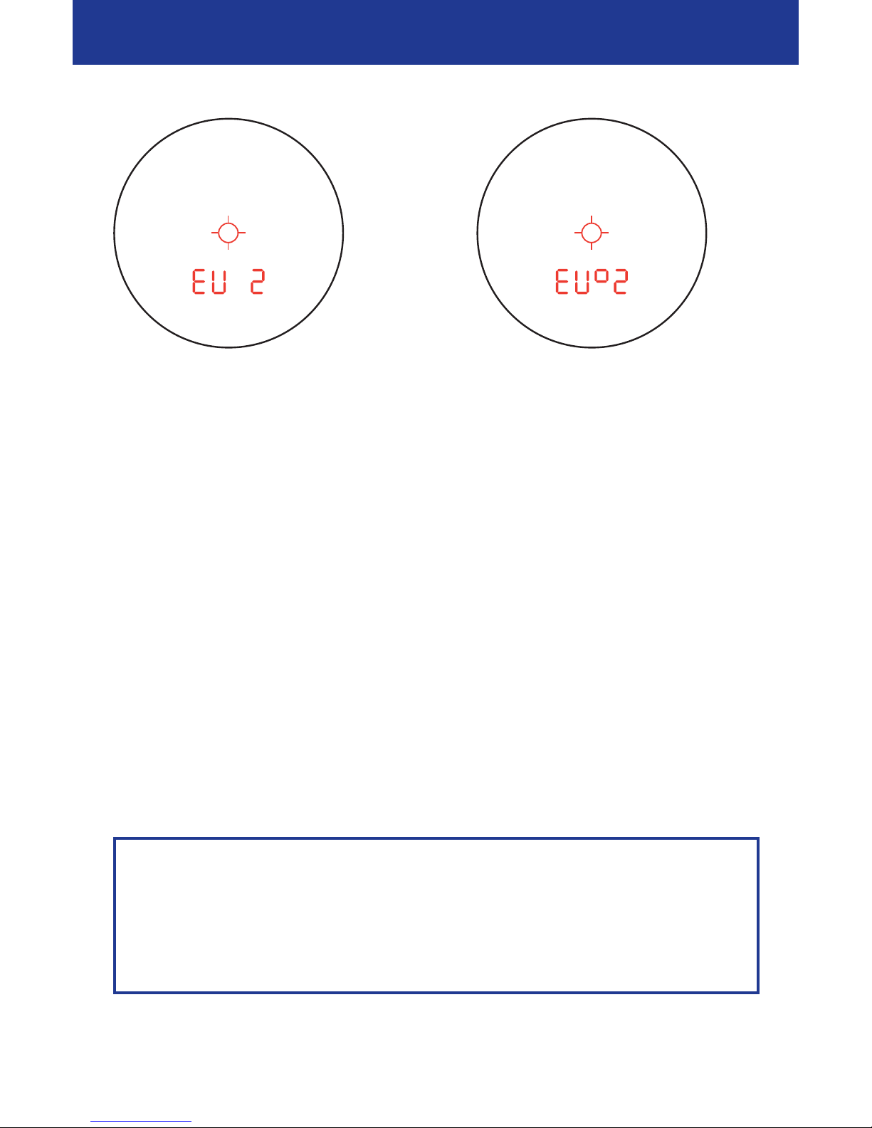
If your riflescope is sighted in at 100 metres/100 yards, select one of the curves
from range EU 1 to EU 6 / US 1 to US 6.
If your riflescope is sighted in at SID/GEE (for EU settings only) or at 200 yards
(for US settings only), select one of the curves from range EU▫1 to EU▫ 6 or
US▫1 to US▫6. The superscript square indicates the longer sight in distance.
Simply release the SET button (Fig. 1/4) at the setting that is appropriate for
you. The ballistic curve displayed previously is then saved. In order to check, a
short press on the SET button at any time will cause the saved setting to be
displayed.
Please note that the ballistic information system BISTM is not to be used as
a replacement for the hunter’s assessment of the situation, but rather to
support and increase hunting safety. We recommend shooting exercises
from different ranges, which can be used to check the correct match of the
specifications with the actual points of impact.
22
Instructions for use

23
Victory 8 x 26 T* PRF
Example:
Program EU 2 is selected:
Bullet drop according
to ballistic curve 2,
range display in metres,
holding point display in centimetres,
sight in distance 100 metres.
Determining the correct trajectory path
The equipment has 6 saved trajectory paths, which cover nearly all calibres.
You must select the most appropriate trajectory path for you depending on the
calibre, bullet type and bullet weight used. Knowledge of the ballistic data
(bullet drop) for the load used is required for selection of the appropriate
trajectory path.
Using the ballistic data for your load, select the appropriate trajectory path
from Tables 1 and 2 for the measuring units of metres/centimetres or from
Tables 3 and 4 for the measuring units of yards/inches.
Caution
The ballistic data are saved for 4 different sight in distances.
The standard sight in distances of 100 metres and SID/GEE are available for
Europe; there is a choice of 100 yards and 200 yards for the USA.
Depending on the estimated range, the correction value for the aiming
points will then be shown by the laser range finder.
Example:
Programm EU▫2 is selected:
Bullet drop according
to ballistic curve 2,
range display in metres,
holding point display in centimetres,
sighting in at SID/GEE.

First select the appropriate table for you, depending on the riflescope sight in
distance:
Sight in distance Table to be used
100 metres Table 1
SID/GEE (corresponds to approx. 4 cm high shot at 100 metres) Table 2
100 yards Table 3
200 yards Table 4
Next, in accordance with the bullet drop of the load used, select the row of the
applicable table in which the values match most closely.
Tip: If you know the bullet drop for 300 metres/yards, simply select the most
appropriate curve from this column only.
Example:
The riflescope is sighted in at SID/GEE and the ammunition being used is
RWS 7x57. According to the manufacturer’s specifications, the point of impact
(bullet drop) is – 42.0 cm at 300 m.
Therefore, Table 2 is used. In the “300 metres” column, the value of – 45.2 fits
most closely with the actual bullet drop. Thus, curve EU▫4should be set on
the product.
Table 1: Selection of the trajectory path for range specifications in metres and
a sight in distance of 100 metres.
Curve Range 100 150 200 250 300 350 400 500
selection in metres
EU 1 0 – 2.1 – 7.7 – 17.1 – 31.2 – 50.5 – 75.3 – 146
EU 2 0 – 2.9 – 10.0 – 22.1 – 39.7 – 63.1 – 94.6 – 184
EU 3 0 – 4.0 – 13.1 – 27.5 – 47.6 – 74.0 – 108 – 203
EU 4 0 – 5.3 – 16.3 – 33.2 – 57.2 – 89.4 – 130 – 239
EU 5 0 – 6.2 – 18.0 – 38.9 – 67.3 – 105 – 151 – 276
EU 6 0 – 8.1 – 25.0 – 51.7 – 91.4 – 146 – 218 – 426
Further information and assistance on this topic
can be found on our website http://www.zeiss.de/sportsoptics
24
Instructions for use
Bullet
drop
in cm

25
Victory 8 x 26 T* PRF
Table 2: Selection of the trajectory path for range specifications in metres and
a sighting in at SID/GEE.
Curve Range 100 150 200 250 300 350 400 500
selection in metres
EU▫14.0 3.9 0.3 – 7.1 – 19.2 – 36.5 – 59.3 – 126
EU▫24.0 3.1 – 2.0 – 12.1 – 27.7 – 49.1 – 78.6 – 164
EU▫34.0 2.0 – 5.1 – 17.5 – 35.6 – 60.0 – 92.3 – 183
EU▫44.0 0.7 – 8.3 – 23.2 – 45.2 – 75.4 – 114 – 219
EU▫54.0 – 0.2 – 10.7 – 28.9 – 55.3 – 90.7 – 135 – 256
EU▫64.0 – 2.1 – 17.0 – 41.7 – 79.4 – 132 – 202 – 406
Note: When EU 0 is selected, the ballistic information system is switched off
and the range is displayed only in metres.
Table 3: Selection of the trajectory path for range specifications in yards and
a sight in distance of 100 yards.
Curve Range 100 150 200 250 300 350 400 500
selection in yards
US 1 0 – 0.5 – 2.1 – 4.9 – 9.2 – 15.1 – 22.8 – 44.2
US 2 0 – 0.8 – 2.8 – 6.4 – 11.8 – 19.1 – 28.5 – 56.8
US 3 0 – 1.1 – 3.7 – 8.1 – 14.4 – 22.6 – 33.2 – 62.7
US 4 0 – 1.5 – 4.7 – 9.9 – 17.4 – 27.3 – 40.0 – 74.5
US 5 0 – 1.8 – 5.4 – 11.6 – 20.4 – 32.1 – 46.9 – 85.9
US 6 0 – 2.0 – 7.2 – 15.4 – 27.4 – 44.0 – 66.0 – 129
Table 4: Selection of the trajectory path for range specifications in yards and
a sight in distance of 200 yards.
Curve Range 100 150 200 250 300 350 400 500
selection in yards
US▫12.1 1.6 0 – 2.8 – 7.1 – 13.0 – 20.7 – 42.2
US▫22.8 2.0 0 – 3.6 – 9.0 – 16.3 – 25.7 – 53.3
US▫33.7 2.6 0 – 4.4 – 10.7 – 18.9 – 29.5 – 59.0
US▫44.7 3.2 0 – 5.3 – 12.6 – 22.6 – 35.4 – 69.8
US▫55.4 3.6 0 – 6.2 – 15.0 – 26.7 – 41.5 – 80.5
US▫67.2 4.9 0 – 8.2 – 20.1 – 36.8 – 58.7 – 122
Note: When US 0 is selected, the ballistic information system is switched off
and the range is displayed only in yards.
Bullet
drop
in cm
Bullet
drop
in inches
Bullet
drop
in inches

26
Instructions for use
Care and maintenance
The laser range finder requires no special care. Do not wipe off coarse dust
(e.g. sand) from the lens, but rather blow it off or remove it using a fine
animal-hair brush. Fingerprints may affect the lens surfaces after a time.
The easiest way to clean lens surfaces is to breathe on them and rub them
using a clean optic-cleaning cloth. Prevention of a fungal film on the optic,
which can occur particularly in the tropics, can be helped by storage in a dry
place and good ventilation of the external lens surfaces.
Spare parts
Should you require spare parts, e.g. such as eye cups or eyepiece caps,
please contact your dealer, the representative for your country, or our
customer service.
We are available for customer service enquiries by telephone from
Monday to Friday between 8.00 and 18.00 CET.
Tel.: +49 (0) 64 41- 4 67 61
Fax: +49 (0) 64 41- 4 83 69
Do not expose the equipment to long periods in the sun without a protec-
tive cap or bag. The lens and the eyepiece can function like a magnifying
glass and damage internal components.

27
Victory 8 x 26 T* PRF
Victory
8x26 T* PRF
Magnification 8 x
Lens diameter 26 mm
Exit pupil diameter 3.25 mm
Twilight number 14.4
Field of view at 1000 m/yd 110 m/yd
Diopter adjustment range ± 3.5 dpt
Exit pupil relief 17.5 mm
Waterproof in accord. with DIN ISO 9022-8
Up to 100 mbar (= 1 metre)
Function temperature2– 10 to + 50 °C
Dimensions (W x H x D) Approx. 98 mm x 48 mm x 130 mm
Weight with battery Approx. 310 g
Measuring range110 – 1300 yards
10 – 1200 metres
Measuring accuracy ±1 m to 600 m / ± 0.5 % over 600 m
Measuring duration Maximum approx. 4 seconds
Laser wave length 904 nm
Laser beam divergence Approx. 4 x 2 mrad
Battery 1 x 3V type CR 2 lithium round cell
Battery life at + 20 °C > 2000 measurements
CE label In accordance with directive 2004/108/EC
EMC EN 55022: Class B and EN 61000-6-2
FDA Compliant with 21 CFR 1040.10 and 1040.11 except for deviations
In pursuance of laser notice no. 50, dated 26th July 2001
EN laser class 60825; 2002 Eye-safe laser class 1M in accordance with EN and FDA
1The range is affected by the size and degree of reflection of the object as well as by the
weather and by exposure to sunlight.
2Low temperature value is limited by battery performance.
Product will also work below –10 °C/14 °F.
Subject to changes in design and scope of delivery as a result of ongoing
technical development.
Technical specifications

9
10
Wir gratulieren Ihnen zu Ihrem neuen Laser-Entfernungsmesser.
Die Produkte der Marke Carl Zeiss sind geprägt durch hervorragende optische
Leistungen, präzise Verarbeitung und eine lange Lebensdauer. Bitte beachten
Sie folgende Gebrauchshinweise, damit Sie Ihr Produkt optimal nutzen
können und es Ihnen über viele Jahre ein zuverlässiger Begleiter wird.
Achtung
Schauen Sie keinesfalls mit dem Laser-Entfernungsmesser in die Sonne
oder Laserlichtquellen. Dies könnte zu schweren Augenverletzungen
führen und das Produkt kann erheblichen Schaden nehmen.
Informationen für Ihre Sicherheit
Laserstrahlung
nicht direkt mit optischen Instrumenten betrachten
Laser Klasse 1M
FCC Class B Compliance Statement
Information to the User
NOTE:
This equipment has been tested and found to comply with the limits for a
class B digital device, pursuant to Part 15 of the FCC Rules and meets all
requirements of the Canadian Interference-Causing Equipment Regulations
(ICES-003). These limits are designed to provide reasonable protection
against harmful interference in a residential installation.
This equipment generates, uses and can radiate radio frequency energy
and, if not installed and used in accordance with the instructions, may
cause harmful interference to radio communications. However, there is no
guarantee that interference will not occur in a particular installation.
If this equipment does cause harmful interference to radio or television
reception, which can be determined by turning the equipment on and off,
the user is encouraged to try to correct the interference by one or more of
the following measures:
●Reorient or relocate the receiving antenna.
●Increase the separation between the equipment and receiver.
●Connect the equipment into an outlet on a circuit different from that to
which the receiver is connected.
●Consult the dealer or an experienced radio/ TV technician for help.
Carl Zeiss Sports Optics GmbH is not responsible for any radio or television
interference caused by unauthorized modifications of this equipment or
the substitution or attachment of connecting cables and equipment other
than
those specified by Carl Zeiss Sports Optics GmbH. The correction of
interference
caused by such unauthorized modification, substitution or
attachment will be the responsibility of the user.
The use of shielded I/O cables is required when connecting this equipment
to any and all optional peripheral or host devices. Failure to do so may
violate FCC and ICES rules.
Gebrauchshinweise User InformationBezeichnung der Bauteile / Part description
Batterie-Entsorgung
Batterien gehören nicht in den Hausmüll!
Bitte bedienen Sie sich bei der Rückgabe verbrauchter Batterien eines in
Ihrem Land evtl. vorhandenen Rücknahmesystems.
Bitte geben Sie nur entladene Batterien ab.
Batterien sind in der Regel dann entladen, wenn das damit betriebene Gerät
– abschaltet und signalisiert „Batterie leer“.
–
nach längerem Gebrauch der Batterie nicht mehr einwandfrei funktioniert
.
Zur Kurzschlusssicherheit sollten die Batteriekontakte mit einem
Klebestreifen überdeckt werden.
Deutschland:
Als Verbraucher sind Sie gesetzlich verpflichtet,
gebrauchte Batterien zurückzugeben. Sie können Ihre alten
Batterien überall dort unentgeltlich abgeben, wo die
Batterien gekauft wurden. Ebenso bei den öffentlichen
Sammelstellen in Ihrer Stadt oder Gemeinde.
Diese Zeichen finden Sie auf schadstoffhaltigen Batterien:
Pb = Batterie enthält Blei
Cd = Batterie enthält Cadmium
Hg = Batterie enthält Quecksilber
Li = Batterie enthält Lithium
21
5
6
7
8
1
2
3
4
Fig. 1
Fig. 2
Fig. 3
Fig. 4 Fig. 5

We make it visible.www.zeiss.de/sportsoptics We make it visible.
Victory
Carl Zeiss
Sports Optics
8x26 T* PRF
Gebrauchshinweise
Instructions for use
Mode d’emploi
Istruzioni d‘impiego
Mode de empleo
Bruksanvisning
Informacje dotyczące użytkowania
Инструкция по применению
Használati utasítás
1508-722/05.08
Carl Zeiss
Sports Optics GmbH
Carl Zeiss Group
Gloelstrasse 3 – 5
D-35576 Wetzlar
Table of contents
Other Zeiss Monocular manuals