Armcor XEM 500 User manual

XEM INSTALLATION &
OPERATION MANUAL
XCHANGE ERV
EXTERNAL MOUNT
XEM 500, XEM 900, XEM 1200, XEM 1700, XEM 2000, XEM 2500, XEM 3500,
XEM 4500, XEM 5000, XEM 6000, XEM 7000, XEM 8000


XCHANGE ERV
EXTERNAL MOUNT
XEM-INSTALLATION & OPERATION MANUAL
WARNING
Improper installation, service, maintenance or use can cause
explosion, fire, electrical shock or other conditions, which
may cause personal injury or property damage and will
void the warranty. Check with Armcor Air Solutions for any
information required on this equipment.
DANGER
Electrical shock can cause personal injury or death. Before
performing any work on this equipment, the electrical
supply must be turned off to avoid the possibility of shock,
injury or damage to the equipment. There may be more
than one power supply circuit.
The XEM series is the standard heat recovery ERV solution for rooftop, ground level or plant
room applications. Available with forward curved centrifugal fans or with EC Plug Fans, these
ERV units utilize the Xchange plate heat exchanger to recover the energy from the exhaust air
and transfer it to the incoming fresh air, resulting in significant energy savings. Both enthalpy
and sensible heat exchange media are available.
Every proposed installation must be subject to an engineered design by a mechanical services
consultant. Armcor Air Solutions is not responsible for performance of equipment in applications
for which the equipment was not designed or specified.
• Only trained and qualified personnel should install, repair
or service heat recovery and/or air handling equipment.
• Installing and servicing equipment can be hazardous due
to electrical and mechanical components.
• When working on equipment, observe precautions in all
literature, tags and labels attached to or shipped with the
unit. Follow all safety codes and guidelines. Wear work
gloves, safety goggles and protective clothing.
• All work must comply with relevant SAA wiring rules
and local authority codes. Installers must ensure that all
statutory regulations and by laws have been addressed.
• Installers must ensure that the structures built to support
the equipment have been suitably constructed for the
purpose, all safety precautions have been applied prior
to installation, and all preparation work has been suitably
sized and installed for its purpose.
EQUIPMENT APPLICATION
SAFETY CONSIDERATIONS
INSTALLATION BY AUTHORISED PERSONNEL
1

XCHANGE ERV
EXTERNAL MOUNT
XEM-INSTALLATION & OPERATION MANUAL
It is important that the selected location for the equipment is
suitable and can adequately accommodate the unit physical
size, the unit weight and has safe and suitable access for
correct operation and future maintenance requirements.
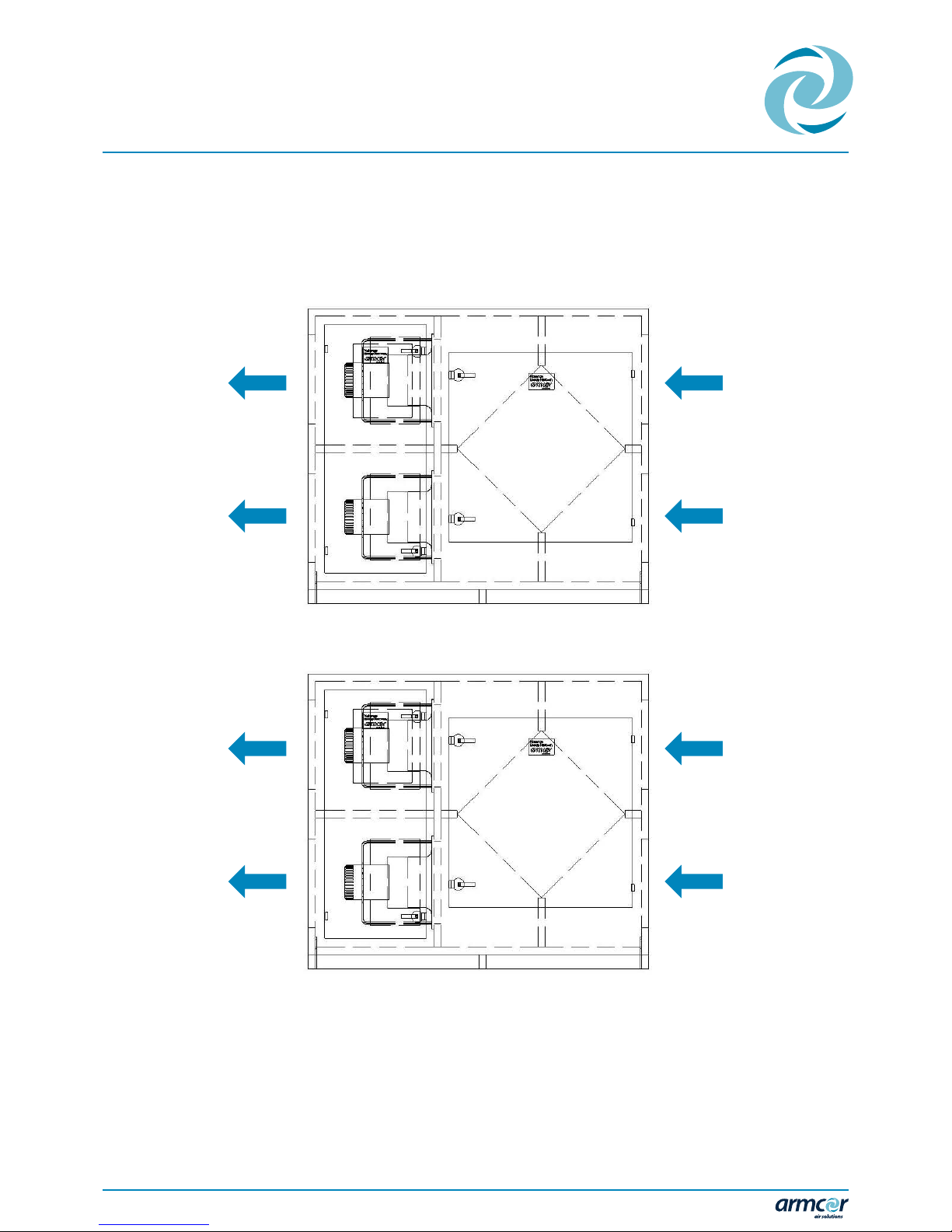
The unit must be mounted so that sufficient space is
allowed for installation and service access. Maintenance
personnel need to gain access to all parts of the unit and
be able to remove components such as fans and filters via
access doors as required.
Unless otherwise specified the following minimum access
should be available:
• 800mm clearance for electrical connections
• 1200mm for all access doors on the unit or if no access
door is provided 1200mm from the front of the unit.
• Every proposed installation must be subject to an
engineered design by a mechanical services consultant.
Armcor Air Solutions is not responsible for installation of
equipment in situations for which the equipment was
not designed or specified.
• Do not locate equipment adjacent to sleeping quarters
unless background noise levels have been checked and
permitted by the appropriate authority.
• It is recommended that rubber supporting or vibration
absorbing pads be used to support the unit to minimise
any vibration being transmitted into the building
structure. We recommend waffle pad to be used under
the base frame and flexible couplings be fitted to the
supply and return ducts to reduce any vibration transfer.
• The location of the fresh air inlets must adhere to the
Australian Standards 1668.2
• The fresh air intake should be positioned clear of
any objects which could obstruct the airflow and be
a minimum distance of 6 metres from any exhaust
discharge ducts from this unit or any other adjacent
equipment. Refer to Australian Standards AS 1668.2
• The fresh air inlet and exhaust air outlet should be fitted
with a cowl or other suitable means of weatherproofing.
• The exhaust discharge should be directed away from any
openable windows.
• Equipment should be installed with a positive fall to
ensure water drains away freely through drain outlets.
Drain lines must be as large as or larger than the fitting to
which the line is being connected.
• All condensate drains must have a‘P”Trap Fitted and have
a minimum fall of 20mm per metre length
• If drain lines are to be extended from the inside to the
outside of the building they must be extended beyond
walls of the building to eliminate the possibility of
damage caused by drain water running down the exterior
surface of the building wall
• When a drain is exposed to freezing temperatures or
subject to the formation of condensation, the drain
should be insulated.
IMPORTANT: ALL UNITS LOCATED IN PLANT ROOMS MUST HAVE DRAIN TRAYS UNDER THE COMPLETE UNIT
MINIMUM ACCESS REQUIREMENTS FOR MAINTENANCE
NOISE LEVELS
FRESH AIR INLET AND EXHAUST AIR OUTLET
DRAINAGE
LOCATION OF EQUIPMENT
2

XCHANGE ERV
EXTERNAL MOUNT
XEM-INSTALLATION & OPERATION MANUAL
• The unit should be inspected upon delivery for possible
external damage incurred during transport. If damage
is evident it should be noted on the freight docket and
contact is to be made with the Armcor Air Solutions
sales office. A claim should be lodged with the shipping
company within 3 days if goods are damaged or
incomplete. No Claims will be recognised after this date
• IF MAJOR DAMAGE IS APPARENT, DO NOT LIFT UNIT ON
TO SITE WITHOUT PRIOR APPROVAL FROM ARMCOR. The
unit was tested and inspected prior to packing and was in
perfect condition at the time at time of despatch.
• Check unit rating plate to ensure the correct unit matches
the job specifications.
• Protective crating or packaging and the pallets should not
be removed until the unit is at the point of installation.
When removing packaging or crating, be careful not
to damage, scratch or dent the unit. After removal of
packaging, all removable access panels should be opened
to inspect for unit internal damage.
• SAFETY – when installing or working on equipment,
always adhere to safety codes and guidelines. Wear
safety goggles, work gloves, work boots and protective
clothing.
• All external units are provided with substantial lifting lugs
on each corner at the base frame. NOTE – All units should
be lifted into position using SLINGS and not CHAINS.
(Chains may damage exterior finish on the fan unit)
• Where units have to be craned into position, installers
must check unit weight is within the safe tolerance of the
working capacity of the crane.
• Prepare for lifting with spreaders as you would do with
lifting air conditioning equipment.
• When lifting equipment never stand under the load.
• Beware of lifting equipment on to roof areas in windy
conditions. Only lift when weather conditions are
favourable.
• Exercise extreme caution when lifting with a forklift. Do
not exceed the height limit of the forklift and never allow
the forklift forks to make contact directly with the bottom
panel of the unit.
• Make careful consideration of the unit’s centre of gravity
and distribute the weight equally on both forks. Test
load to see if the weight is equally distributed. Do this
by lifting the unit a few centimetres off the ground level
and checking stability before lifting any further or before
transporting the unit.
• Before suspending the unit, check the supporting beams
have sufficient load carrying capacity to support the
weight of the unit. Equipment is supplied with brackets
to support the unit.
• We recommend that all ceiling mounted units be
suspended or supported with suitable mounting springs
to eliminate the transmission of vibration.
UNIT HANDLING
LIFTING WITH A CRANE
LIFTING WITH A FORKLIFT
SUSPENDING THE UNIT
UNPACKING AND INSPECTION
INSTALLATION INSTRUCTIONS
3

XCHANGE ERV
EXTERNAL MOUNT
XEM-INSTALLATION & OPERATION MANUAL
• Air distribution ductwork must be designed to allow
for the specified air flow without excessive pressure
levels. The unit should be situated as close as possible
to the point of use to prevent unnecessary long runs of
ductwork.
• Sheetmetal ductwork is recommended for use with all
Armcor Air Solutions equipment.
• Ducts should be insulated in accordance with BCA
Section J-5
• Fan inlet conditions can affect the fan performance,
particularly where duct bends cause a non-uniform flow
and swirl at the inlet. To reduce losses due to fan systems
effect, adequate length of straight duct between any
elbow and the fan inlet should be provided or turning
vanes used in the elbow.
• Poor fan outlet conditions will also affect the fan
performance. We recommend a minimum of 1000mm of
straight duct directly after the fan outlet.
• 50mm panel filters are a minimum recommendation for
all equipment.
• Filters must be fitted to fresh air and/or return air. Where
there is no provision for filters within the unit, the
installing contractor is responsible to incorporate filters
in the ductwork system external to the unit.
• It is recommended that temporary disposable filters are
used during construction and commissioning
• Where a Heat Exchanger is incorporated in the equipment,
warranty is void if filters are not fitted.
IMPORTANT: NEVER OPERATE A UNIT WITHOUT FILTERS FITTED TO THE RETURN AND FRESH AIR INTAKES.
• The power requirement and voltage are detailed on
the equipment technical specifications (available
on our website www.armcor.com.au) and are on the
identification/serial no. plate attached to each unit.
• An electrical diagram is attached to the electrical box on
the unit.
• A single phase power supply rated at 240v (+/- 5%) 50Hz
or a 3 phase power supply rated at 415 volts is required to
operate the unit within manufacturer’s tolerance. Check
the name plates for correct voltage.
• We recommend an isolator be mounted externally to the
unit (not supplied) and a suitably sized circuit breaker
mounted back at the distribution board to provide local
isolation during service and maintenance periods.
• Main cables and control circuit wires are to be connected
as per wiring diagram.
• All wiring must comply with relevant local wiring
regulations.
• The units require a main circuit breaker or HRC fuse
capable of handling the full load of the unit and selected
in accordance with SAA Wiring Rules.
• All wiring is to be independently colour coded.
• Single phase fan motors are internally protected and
there is no need for external overloads.
EQUIPMENT CONNECTIONS
DUCTWORK
FILTERS
ELECTRICAL REQUIREMENTS
MAINS POWER SUPPLY AND FUSING
4

XCHANGE ERV
EXTERNAL MOUNT
XEM-INSTALLATION & OPERATION MANUAL
5
EXHAUST AIR
EXHAUST AIR
FRESH AIR
FRESH AIR
SUPPLY AIR
SUPPLY AIR
RETURN AIR
RETURN AIR
STANDARD EQUIPMENT LAYOUT
These diagrams show units with EC Plug Fans. These layouts are also available for units fitted with Certrifugal Fans
OPTION 1 AND 2 DO NOT REQUIRE ANY CHANGES TO THE FAN POSITIONS INSIDE THE UNIT.
RETURN AIR Air that is drawn from conditioned area.
EXHAUST AIR Ducted to outside the building or into the roof space if adequate ventilation is available.
FRESH AIR Use a fresh air cowl or grill to introduce fresh air.
SUPPLY AIR Connect to the Airconditioning system or directly into the conditioned area.
OPTION 1
OPTION 2

XCHANGE ERV
EXTERNAL MOUNT
XEM-INSTALLATION & OPERATION MANUAL
• All Armcor equipment is designed for easy maintenance.
• Preventative maintenance programs will vary according
to actual operating conditions and location and hours of
usage by the client.
• Armcor Air Solutions are pleased to provide expert
advice on special service maintenance requirements for
particular installations.
• Monthly maintenance is usually focused on air filters and
visual checks to monitor any operational deficiencies.
The type of filter and frequency of cleaning should
be addressed by the installing contractor to suit the
customer’s requirements.
• Filters should be inspected immediately after installation
to confirm the frequency of cleaning needed for the
particular location. Regular change/clean of filters is
necessary to ensure normal operating conditions.
• Check condensate drain (if applicable) for free drainage
• Disposable Corrugated Filters. Ordinary disposable
corrugated filters should last approximately one month in
normal commercial use, or longer depending on usage.
• Cleanable Filters. If filters are cleanable, they should
be cleaned once a month and the filter media should be
replaced every 12 months.
• Repeat the monthly schedule.
• Check blower wheels for dirt build-up and tightness on
shaft.
• Check all cabinet panels for correct fitting, alignment and
seals, and clean cabinets as required. Ensure no insulation
has been detached from the panels.
• All electrical terminals should be checked for tightness.
IMPORTANT – Ensure the with main switch is
turned off.
• Check and clean heat exchangers, heating/cooling coils,
drain trays and outlets. (If applicable). Vacuum or brush
clean as necessary.
• Repeat monthly and three monthly checks.
• Check cabinet for any paint chips or abrasions and treat
accordingly.
• Check and record the available voltage and amperage of
each phase.
• Check and record the amperage of each motor against
nameplate details.
• Check and record refrigerant gas pressures (if applicable)
IMPORTANT: Failure to carry out regular maintenance with a licensed and reputable service company
may render warranty claims invalid, if faults have been caused by lack of proper maintenance. Armcor Air
Solutions may request to see the maintenance schedule carried out.
GENERAL
MONTHLY MAINTENANCE SCHEDULES
GUIDE TO HOW FREQUENCY ACCORDING TO USAGE IS ESTABLISHED
THREE MONTHLY CHECKS MAINTENANCE SCHEDULES
ANNUAL MAINTENANCE SCHEDULES
MAINTENANCE SCHEDULE
6

Armcor Air Solutions
109-111 Northcorp Blvd, Broadmeadows 3047
P1800 244 556 Esales@armcor.com.au
www.armcor.com.au
Date: 20/10/2016 Document: XEM Installation Manual Version Number: V2
XCHANGE ERV CEILING MOUNT
EXTERNAL MOUNT UNITS
XEM-INSTALLATION & OPERATION MANUAL
The standard Armcor warranty policy is a parts only
warranty for a 12 month period. If any defect in your Armcor
equipment is caused by FAULTY MATERIALS within the
warranty period, starting from the date of original purchase
it will be rectified or replaced without cost.
Additional labour warranty is available and must be
purchased at the time of ordering in accordance with the
warranty policy.
• Consequential damage
• Failure to start due to voltage conditions, blown fuses
or other damage cause by inadequate or interrupted
electricity supply
• Damage caused by accident, misapplication, abuse,
alteration, tampering or servicing by anyone other than
an authorized person
• Damage resulting from incorrect installation,
commissioning or use other than in accordance with the
installation and operating instructions issued by Armcor
Air Solutions
• Damaged caused by using equipment being located in a
corrosive atmosphere or by filter neglect
• Replacement of any worn drive belts if applicable
• Costs incurred for regular maintenance services
• The original service call costs in identifying a warranty
claim
• Freight and travel changes for work performed or parts
supplied outside of all capital cities in Australia
• Field wiring, refrigerant pipe run between units, the
condensation drainpipe or other accessories
• Any warranty work performed by Armcor Air Solutions
outside of Melbourne metro area will require the installing
contractor to provide free of charge: Oxy/Acetylene
Equipment, Dry Nitrogen, Vacuum Pump, Refrigerant Gas,
Reclaim Bottles, Recovery Unit, and any other associated
refrigerant tools.
• Any appliance plate is altered or removed
• Armcor Air Solutions has not be notified within 48 hours
of any fault occurring which may require warranty work
• Any unauthorized modification has been made to the
equipment or any part has be substituted or replaced
with non-original items
• Regular service has not been carried out by an appropriate
Armcor approved, licenced installer
• The unit is used other than for the heating and cooling
of air for human comfort – unless approved by Armcor
Air Solutions
• The system is installed in a mobile application (eg.
caravan, boat, crane)
Complete a warranty form available on our website www.armcor.com.au and return the Armcor Warranty Request Form
to: service@armcor.com.au
Contact us direct by phone on 1800 244 556 or email service@armcor.com.au
WHAT THE WARRANTY POLICY COVERS
WHAT THE WARRANTY POLICY DOES NOT COVER
THE WARRANTY WILL NOT APPLY IF;
HOW TO MAKE A WARRANTY CLAIM
WARRANTY
7
The Armcor Air Solutions Warranty Policy should be read in conjuction with the
Terms and Conditions of Sale. These are available on our website - www.armcor.com.au.

XCHANGE ERV
EXTERNAL MOUNT
XEM-INSTALLATION & OPERATION MANUAL
PRE-START CHECK LIST
UNIT INSTALLATION AND CONNECTIONS
Check that equipment is fully installed in accordance with the installation instructions
Visually check that air flows will not be obstructed
ELECTRICAL
Visually check all field wiring
Tighten all electrical connections including all factory wiring connections
Ensure supply cable is correct size
Check the required supply voltage is available on all phases
Check overload settings are correct (if applicable)
FILTERS
Check that both the fresh air and return air have adequate filters before starting unit
STARTING UNIT
Check Fans and Air Flows
Turn on all circuit breakers
Make sure all dampers are open
Turn on control circuit and activate fans
Turn on supply fan, run and conduct an air balance (Fans do not require phase rotation)
Turn on exhaust fan, run and conduct an air balance
Check fan current draw for each fan individually
8

XCHANGE ERV
EXTERNAL MOUNT
XEM-INSTALLATION & OPERATION MANUAL
COMMISSIONING CHECKLIST
GENERAL
Air Filters: Overall Size and Number
Drain Pipe Traps and Vents fitted to Indoor Unit as per Installation Instructions Y / N
Drain is Clearing Water Properly Y / N
Check Vibration of Unit OK / EXCESSIVE
Belt Tensioning Adjusted Y / N
Paint Finish Checked and Repaired Y / N
DUCTING
Total Return Air Flow (Total of all inlets) (L/s)
Total System external resistance (Pa) Measured downstream of fan outlets plus upstream of Coil (s)
Estimate of Fresh Air Make Up (% or L/s)
ELECTRICAL
Supply Voltage
Supply Unit Fan Motor Amps
Exhaust Fan Motor Amps
Total Unit Amps
Thermostat Settings (ºC)
Thermostat Operating Correctly Y / N
Contactors & Relays Operating Correctly Y / N
All Terminals Checked for Tightness and Label signed Y / N
EVAPORATIVE COOLING PADS
Water Pump Operating Correctly Y / N
Even Distribution of Water over Celdek Pad Y / N
Sump Level is correct when unit is turned off Y / N
9
This manual suits for next models
11
Table of contents