Armstrong-Yoshitake, Inc. GD-30 User manual

Model GD-30, GD-30S
Pressure Reducing Valve
Installation and Maintenance Instructions
This bulletin should be used by experienced personnel as a guide to the installation of the Model GD-30 and GD-30S
Pressure Reducing Valve. Selection or installation of equipment should always be accompanied by competent technical
assistance. You are encouraged to contactArmstrong International, Inc. or its local representative for additional
information.
Bulletin No. AY-764-B
Installation for Steam Service
Installation for Air Service
Installation Instructions
1. AnArmstrong InvertedBucket SteamTrap is
recommendedto drain condensateat theinlet ofthe
Pressure Reducing Valve (PRV). ALiquid Drainer is
recommendedforair service.
2. AnArmstrong Y-Strainer(20-100mesh, dependingon
system dirt) should be installed before the PRV to
reducethe chanceof dirtfouling.
3. Pressuregauges shouldbe installedbeforeand after
the PRV.
4. If system cannot be turned off to service PRV then
pipinga by-passline witha highquality globevalve
aroundthe PRVwill allow manualsystem operation
while the PRV is being serviced.
5. Donot installquick openingor closingvalves down-
stream of the PRV.
6. Install the PRV with the flow in the direction of the
arrowon thebody.

2
Troubleshooting Guide
1. Closethe gatevalvesbefore andafterthe pressure
reducingvalve. Open theglobevalve slowlyin the
bypass line and blow down the inlet piping. Adjust the
openingof thebypassvalve sothe safetyvalve does
not blow. After blowing the system down, close the
bypassvalve.
2. Slowly open the inlet side gate valve to the fully open
position,and partially openthe outlet valveso only a
small amount of steam or air can pass.
Start-Up and Adjustment Procedures
Improperadjustment ofthe pressurereducing valvemay causehunting, scaleproblems, waterhammer, etc.,and
damageto thevalve itself. Damagedpressure gauges,leakage oropening ofa bypassvalve, orclogging of aninlet
strainermay causeproblems similarto thatof amalfunctioning reducingvalve.
Adjustthe valveas follows:
3. Toincrease thedownstream pressure,place yourhand
onthe top ofthe adjusting handleand pullvertically
up. When in the fully up position turn the handle
clockwise until the desired pressure is obtained on the
downstreampressuregauge.
4. Release the handle and it will automatically retract
which will lock the adjusting handle in place.
5. Slowlyopen theoutlet valveto the fullyopen position.
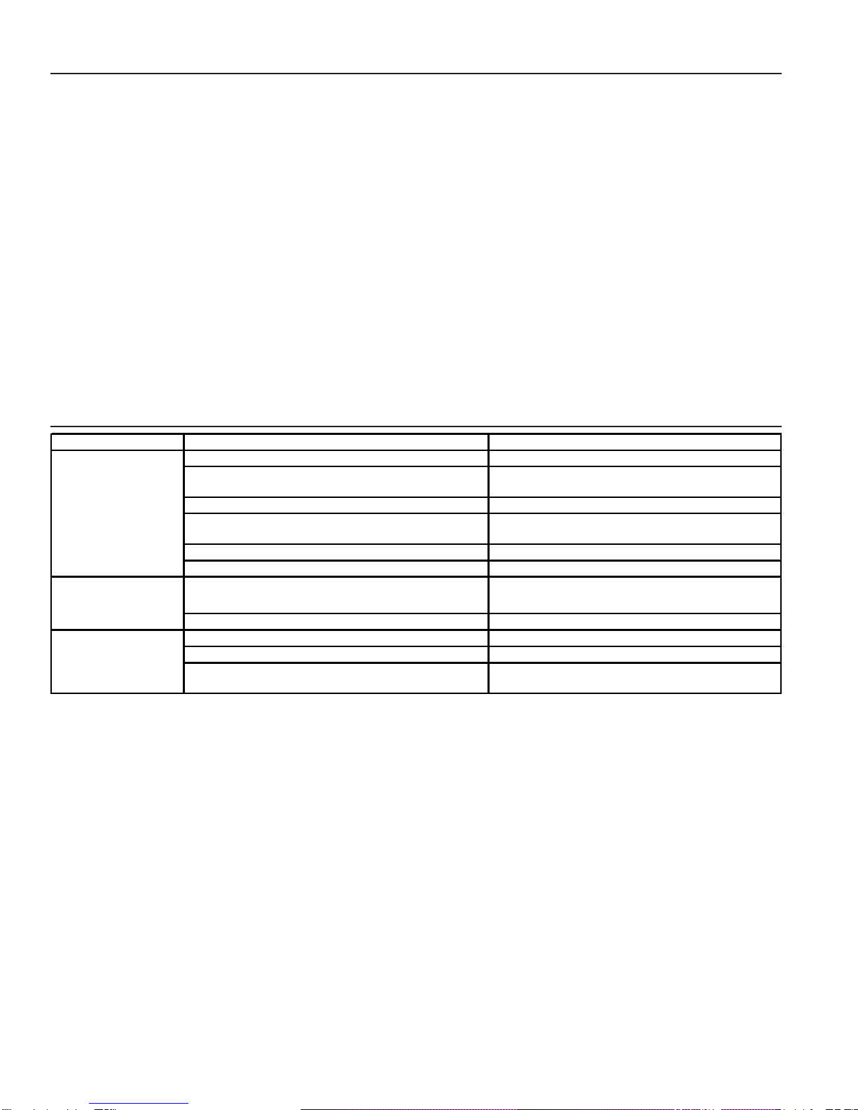
Problem Causes Solutions
The inlet pressure is too low or high. Change the pressure to the appropriate level.
The sensing port of the outlet pressure is clogged with
foreign matter. Disassemble and clean the sensing port.
The valve size is smaller than what is required. Change the valve size to the appropriate one.
The adjustment is not appropriate. Readjust according to the adjustment procedure.
(See start-up procedure)
The inlet strainer is clogged by foreign substance. Disassemble and clean the strainer.
The pressure gauge is not functioning properly. Replace the pressure gauge.
The valve or valve seat is contaminated by foreign
substance. Disassemble and clean the valve or the seat.
The by-pass valve is leaking. Repair or replace the by-pass valve.
The reducing ratio is excessively large. Reduce pressure by staging with second PRV.
Water hammer (for steam service). Install a steam trap at the reducing valve inlet.
There is a fast closing valve near the PRV. Provide as long a distance as possible between
the two valves.
The desired pressure
cannot be obtained.
The outlet pressure
rises higher than the
specified pressure
Abnormal noise is
heard.

3
GD-30 1/2” - 1”
Valve Seat (6)
Cap (3)
Gasket (16)
Screen (9)
Spring (13)
Valve (7)
Body (1)
Valve Rod (8)
E-Ring (20)
Gasket (17)
Bellows (10)
Nameplate (23)
Push Nut (22)
(Adjusting Screw)
Spring Pin (19)
Split Pin (21)
Spring Housing (2)
Adjusting Screw (11)
Spring (12)
Spring Retainer (25)
Flat Washer (18)
Bolt (15)
Handle (4)
Spring (14)
Disassembly
1. Eliminate pressure from inside the valve. Make
surethe valveis completelyfree from pressure.
2. Pull up and turn the handle (4) in the direction
(counterclockwise)as shownon thenameplate
ofthe handleto make thespring (12)free
(notloaded).
3. Remove the bolts (15) and take away the spring
housing(2) (thehandle cannotbe disassembled).
Takeoutthe spring(12), bellows(10) andvalverod (8).
4. Unscrew (counterclockwise) the cap (3) and take
outthe spring(13), screen(9) andvalve(7) fromthe
body(1).
Reassembly
1. Check all parts to make sure they are in good
conditionbefore puttingback together.
2. Lapvalve(7) andvalveseat (6)with1000 grit
lappingcompound ifneeded toensureno leakage.
3. Reassemblein reverseorder asdisassembly.
Note: Replace all gaskets where disassembly is required.

Armstrong-Yoshitake, Inc.
221 Armstrong Blvd., P.O. Box 408, Three Rivers, Michigan 49093 - USA Ph: (616) 279-3600 Fax: (616) 273-8656
Steam Traps \ Humidifiers \ Steam Coils \ Valves \ Air Vents \ Pumping Traps \ Water Heaters
www.armstrong-intl.com
Bulletin No. AY-764-B 5/01 Printed in U.S.A.
GD-30 1-1/2 - 2”
(Adjusting Screw)
Small Spring
Pin (24)
Spring Housing (2)
Rivet (25)
Adjusting Screw (12)
Bottom Spring
Plate (10) Cap (3)
Screen (8)
Spindle (5)
Valve Seat (4)
Body (1)
Spindle (6)
E-Ring (16)
Bellows Gasket (14)
Bellows (9)
Main Valve
Spring (7)
Cap Gasket (15)
Adjusting Spring (13)
Spring Plate (11)
Flat Washer (18)
Bearing (17)
Bolts (19)
Large Spring
Pin (20)
Handle (22)
Bush Nut & Spring (23)
Nameplate (24)
Nameplate (24)
Disassembly
1. Eliminate pressurefrom insidethe valve. Make
surethe valveis completelyfree from pressure.
2. Pull up and turn the handle (22) in the direction
(counterclockwise)as shownon thenameplate
ofthe handle tomake the adjustingspring (13)
free(notloaded).
3. Removethe bolts(19) andtake away thespring
housing(2) (thehandle cannotbe disassembled).
Takeout theadjusting spring (13),bellows (9)
andspindle (6).
4. Unscrew(counterclockwise) thecap (3)and take
outthe mainvalve spring(7), screen(8)and
spindle(5) fromthe body(1).
Reassembly
1. Check all parts to make sure they are in good
conditionbefore puttingback together.
2. Lapspindle (5)and valveseat (4) with1000 grit
lappingcompound ifneededto ensureno
leakage.
3. Reassemblein reverseorder asdisassembly.
Note: Replace all gaskets where disassembly is required.
This manual suits for next models
1
Popular Control Unit manuals by other brands

SimCom
SimCom SIM900B EVB user guide

BNC
BNC 588-OEM 250ps user manual

Control Technology Inc.
Control Technology Inc. CTI 2559-TC Installation and operation guide

Telit Wireless Solutions
Telit Wireless Solutions GE866-QUAD Hardware user's guide

Lenze
Lenze E94AZMAC Mounting instructions

Ziton
Ziton ZP3-ECU Installation and commissioning manual

Intelligent Appliance
Intelligent Appliance IA-2104-U user manual

Jag
Jag FB2 Installation, operation & maintenance manual

Siemens
Siemens 3VM9.88-0LB10 operating instructions

Böning
Böning AHD 903BS manual

Dallmer
Dallmer Stausafe RS manual

oventrop
oventrop Hydrocontrol VFC Installation and operating instructions