Armstrong Steam QM-3 User manual

Steam QM-3 Steam Quality Monitor
Installation and Operation Manual
IOM-245-V2.1
Armstrong InternationalArmstrong International
Parc Industriel des Hauts-Sarts, 2ème avenue 4, 4040 HERSTAL - BELGIUM
Tél: +32(0)4 240 90 90 Fax: +32 (0)4 240 40 33 armstrongarmstronginternational.com
Keep this manual with equipment
for future reference.
Certified by

Armstrong InternationalArmstrong International
Parc Industriel des Hauts-Sarts, 2ème avenue 4, 4040 HERSTAL - BELGIUM
Phone: +32(0)4 240 90 90 Fax: +32 (0)4 240 40 33 armstrongarmstronginternational.com
Armstrong
Contents
Revision History . . . . . . . . . . . . . ..1
Safety . . . . . . . . . . . . . . . . . . ..2
Abbreviations and Acronyms. . . . . . . . . .3
General Description . . . . . . . . . . . ..4
Calorimeter Assembly . . . . . . . . . . . . . . . . . . . . . . . . . . . . . . . . . . . ....5
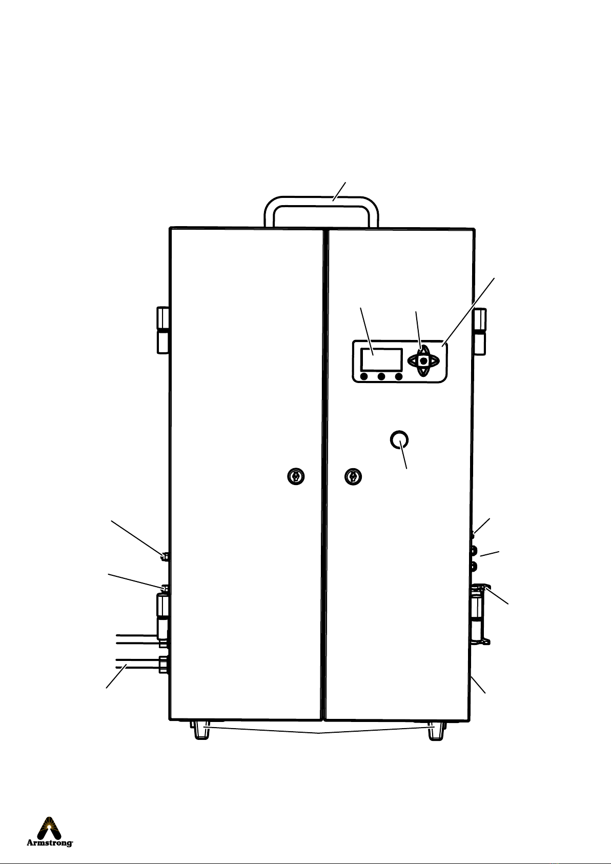
Cabinet Exterior . . . . . . . . . . . . . . . . . . . . . . . . . . . . . . . . . . . . . . . . . . . . ....6
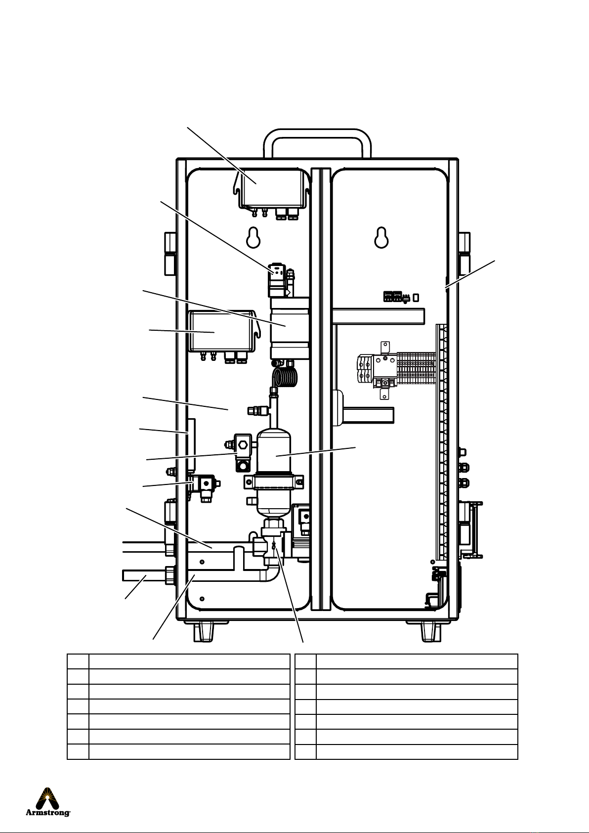
Cabinet Interior . . . . . . . . . . . . . . . . . . . . . . . . . . . . . . . . . . . . . . . . . . . . . ....7
Specifications . . . . . . . . . . . . . . . . . . . . . . . . . . . . . . . . . . . . . . . . . . . . . . . ....8
Installation . . . . . . . . . . . . . . . . . .9
General Considerations (Site Selection). . . . . . . . . . ....9
Typical Installation . . . . . . . . . . . . . . . . . . . . . . . . . . . . . . . . . . . . . . . .10
Start-Up Procedure . . . . . . . . . . . . .14
Software Navigation. . . . . . . . . . . . . 15
Standard Screens . . . . . . . . . . . . . . . . . . . . . . . . . . . . . . . . . . . . . . . . . . 15
Special Screens . . . . . . . . . . . . . . . . . . . . . . . . . . . . . . . . . . . . . . . . . . . .17
Troubleshooting . . . . . . . . . . . . . . . 19
Software update. . . . . . . . . . . . . . . 24
Component and Parts List . . . . . . . . . . 25
Product Certifications . . . . . . . . . . . . 26
Appendix One: Wiring Diagram . . . . . . .27
Appendix Two: Principle Schematic . . . . .28
Appendix Three . . . . . . . . . . . . . . . 29
MODBUS Connection . . . . . . . . . . . . . . . . . . . . . . . . . . . . . . . . . . . . . 29
Limited Warranty and Remedy. . . . . . . . 30

Armstrong InternationalArmstrong International
IOM-245-V2.1
Steam QM-3
Page 1 of 30
Revision History
Version Release Date Description of Changes
1.0 28/11/2013 Initial
1.1 22/01/2013 Temperature transmitter T (T1, T2, T3) - Design Modification
2.0 17/03/2016 Tee and Adapter - Design Modification
page 5: update of the calorimeter assembly graphic according to new design.
page 6: update of the cabinet exterior graphic according to new design.
page 7: update of the cabinet interior graphic according to new design.
page 9: update of the calorimeter assembly and cabinet exterior graphics.
correction: dimension conversion lenght 3m => 118"
page 10: update of the typical installation for vertical or side of horizontal steam line graphic. Add
comment on the cable connecting Harting Plus to sensors.
page 11: update of the typical installation for top of horizontal steam line graphic.
page 12: Text modifications for point 5, 8 and 9
Add "Drain Hose Specifications" chart.
page 17: Special Screens. Advanced Setting Menu: updates of the Screen with adding of the Serial
Mode information. Special Screens. Calibration Menu Screen: update of the data into the screen
(V230).
page 18: Add drain menu procedure.
page 25: adding List of component and parts.
page 26: update of the ETL Electrical Safety Listings logo.
page 29, Appendix Three: update data logger (MODBUS) connection (master and slave modes).
All document:
SteamLog eWon data logger not available anymore, all references deleted from document.
Yokogawa information deleted from document.
2.1 31/07/2020 page 8: Electrical parmameter - add : (±10 %)
page 9: add Indore use and Pollution Degree 2 to General Consideration (Site Selection) §

Armstrong InternationalArmstrong International
IOM-245-V2.1
Steam QM-3
Page 2 of 30
Safety
Icon Legend
Burn hazard! Uninsulated components upstream of cabinet may be hot.
• Do not touch when unit is working.
• Allow to cool before moving or servicing unit.
Live steam will cause burns; condensate water may cause them. Skin exposure
to 140 °F (60 °C) water for only five seconds may cause a second degree burn.
This device must be installed in accordance with appropriate local,
national, and international standards, codes, and practices.
Read this manual. It contains important information.
Service must be performed by a qualified person.
Installation should always be accompanied by competent
technical assistance.
Improper installation, start-up, operation, maintenance, or service
may void warranty.
You are encouraged to contact Armstrong International or its local
sales representative for additional information.
Shock hazard! High voltages present inside equipment.
• Electrical installation must be performed by qualified personnel.
• Disconnect power before performing any electrical service.
Equipment must be disposed of according to applicable
environmental requirements.
Indicates Power On
Indicates Power Off
Indicates important information concerning potential
for personal injury or damage to equipment
Indicates electrical hazard
Indicates hot surface
Keep unit away from heat-sensitive equipment and installations.

Armstrong InternationalArmstrong International
IOM-245-V2.1
Steam QM-3
Page 3 of 30
Abbreviations and Acronyms
Term Meaning Explanation
∆P Differential Pressure ∆P1: Difference between water column in NCG vessel and atmosphere.
∆P2: Difference between water column in condensate vessel and atmosphere.
Al Alarm Indicates an out-of-limit situation, but has no impact on operation.
Al1: Dryness below user-defined set point longer than two seconds.
Al2: Four consecutive calculations of NCGs are over the user-defined limit. This calculated
value is displayed on the main screen and updated every 30 seconds.
Al3: T1 above 257 °F (125 °C) longer than two seconds.
C Celsius
cm Centimeter
Df Default Indicates failure. Turns off power to heating element and opens EV0to drain.
Df4: T3 above 185 °F (85 °C) longer than two seconds.
Df5: No condensate from condenser in last ten minutes.
Df6: T2 above 356 °F (180 °C) longer than two seconds.
DIN Deutsches Institut für Normung eV
dP Differential Pressure
EC European Community
EEC European Electrotechnical Commission
EN European Norm
EV Electronic Valve
F Fahrenheit
gal Gallon
h Hour
imp Imperial [measure]
in. Inch
kg Kilogram
L Liter
lb(s) Pound(s)
max Maximum
min Minimum
mm Millimeter
NCG Non-Condensable Gases NCGmax is the limit of the NCG rate. Alarm 2 indicates the limit has been exceeded. Range is
0–15%. Default is 3.5%.
P Pressure P is steam pressure upstream of calibrated orifice. Modbus sends data as bar even with
imperial measure selected.
ppm Parts per Million
psi(g) Pounds per Square Inch (gauge)
Q Steam Flow
QM Quality Monitoring
R Resistance Shown as watts.
R/O Reverse Osmosis
sec(s) Second(s)
SI International System of Units
STSuperheat
T Temperature T1: Temperature after pressure reduction to atmosphere.
T2: Temperature after heating resistance.
T3: Temperature after condenser.
X Dryness Fraction (sometimes called steam
quality or moisture content)
Xmin is the lower dryness limit. Alarm 1 indicates the limit has been exceeded. Range is
0.85–0.95. Default is 0.95.

Armstrong InternationalArmstrong International
IOM-245-V2.1
Steam QM-3
Page 4 of 30
General Description
Steam QM-3 is intended to replace manual testing of
pure steam and provide real-time data proving that steam
quality meets applicable requirements.
Advantages over manual testing are:
• Improved safety
• Ease of use
• Reduced time per test
• Reduced cost per test
• More accurate and objective results
• Ability to trend data over time
Steam QM-3 is set up and calibrated to test for parameters
defined in EN285 standard. It performs three tests:
• Calculating dryness
• Calculating superheat
• Quantifying non-condensable gases (NCG)
(NCG measurement is performed first. If it is within range,
dryness and superheat measurements will be performed.)
Data from Steam QM-3 can be recorded using a data historian with Modbus
output (see appendix three on p. 29 for connection information.)
Armstrong strongly recommends that the Steam QM-3 unit be installed in one location and
not used for checking multiple steam outlets.
It is possible to use one unit for multiple locations and it could be installed for portability at
customer's preference. Note however that:
• Calorimeter assemblies and cabinets are matched sets and are not interchangeable.
• Moving both calorimeter and cabinet to alternate locations as a unit is preferred.
• If one cabinet is connected to a different calorimeter, it must be recalibrated prior to use.
Armstrong reserves the right to make design or
specification changes without notification.
Materials of construction comply with all
standards known at the time of manufacture.

2
Armstrong InternationalArmstrong International
IOM-245-V2.1
Steam QM-3
Page 5 of 30 Calorimeter Assembly
3
4
Steam to cabinet (flexible
hose not shown)
Connection to
steam line
7
Alternate steam line connection
(if chamber must be rotated)
Calorimeter Assembly
Note: The assembly shown below is configured
for connection to a vertical steam line.
Calorimeter assembly weighs
approximately 11 lbs (5 kg).
1 Inlet tee
2 Sanitary clamp
3 P pressure transmitter
4 Calibrated orifice (inside connection)
5 Calorimeter
6 Sanitary clamp
7 Steam line from calorimeter to
superheating chamber (not visible)
8 Superheating chamber
9 Drain (6 mm)
10 Tee
11 T1 temperature transmitter
12 T2 temperature transmitter
13 Heating Element
11
5
1
8
10
12
9
6
13

12
Armstrong InternationalArmstrong International
IOM-245-V2.1
Steam QM-3
Page 6 of 30 Cabinet Exterior
Cabinet Exterior
RS485 con-
nection (M12)
Handle
Wheel (back)/Foot (front)
Harting
connector
Steam from
calorimeter
Condensate drain
Power On
indicator light
Navigation
Pad
Display
Electrical
connection and
power switch
(not visible)
Auxiliary
(unused)
connections
Cooling water
inlet
Cooling water
outlet
Cabinet weighs approximately
42 lbs (19 kg).

Armstrong InternationalArmstrong International
IOM-245-V2.1
Steam QM-3
Page 7 of 30 Cabinet Interior
9
7
10
5
3
4
2
1
8
Condensate drain
Steam from
calorimeter
Cabinet Interior
6
11
8 EV2 solenoid valve
9EV0solenoid valve
10 Condenser
11 Relay board with solenoid LED
12 Main screen (consult page 6)
13 Cabinet steam inlet
14 Cabinet condensate outlet
1 NCG pressure differential sensor
2 EV1 solenoid valve
3 NCG burette
4 Condensate pressure differential sensor
5 T3 temperature sensor
6 Condensate burette
7 EV3 solenoid valve
14
13

Armstrong InternationalArmstrong International
IOM-245-V2.1
Steam QM-3
Page 8 of 30 Specifications
Specifications
Parameter Specification
Calorimeter operating temperature range (T1) 0 –150 °C (32 – 302 °F)
Maximum allowable calorimeter temperature (T1) 180 °C (356 °F)
Calorimeter operating saturated steam pressure range (P) 0,5 – 4 barg (7 – 60 psig)
Superheated steam operating temperature range (T2) 0 – 180 °C (32 – 356 °F)
Dryness fraction 0,85 – 1
Dryness fraction accuracy ± 0,01 of display
Non-condensable gases content ≤ 15%
Condensate temperature range (T3) 0 – 80 °C (32 – 176 °F)
Operating condensate temperature (T3) 65 °C (149 °F )
Estimated steam consumption 1,5 kg/h (3,3 lbs/h ) @ 3 barg (45 psig)
Estimated water consumption 15 L/h (4 gal/h ) @ 10 °C (50 °F)
Electrical 115/230 VAC (±10 %)
50/60 Hz
100 W

Armstrong InternationalArmstrong International
IOM-245-V2.1
Steam QM-3
Page 9 of 30 General Considerations (Site Selection)
Installation
General Considerations (Site Selection)
Superheating chamber must be installed
within 45° of vertical to front or back.
Attachment to vertical steam line is optimal.
Mounting both calorimeter and cabinet is
required. Cabinet must be mounted on a
wall. Mounting hardware is supplied.
• Use one or both sections of flex hose provided depending
on installation
• Length must not exceed 3 m (118 in.)
• Hose must run down from calorimeter assembly to cabinet
with no low spots where pools of condensate could form
Attachment to horizontal
steam line must be at
center line or above.
Connecting to top of
horizontal line may result in
elevated dryness readings.
Note: Where necessary outlet on heating chamber can be
rotated 180° to accommodate left or right cabinet position.
See instructions below (p. 11).
Unit must be installed with the following utilities nearby:
• Cooling water supply
• Drain
• Grounded power source with required voltage (alternative
grounding of unit is permissible, but grounding is required)
Ambient temperature must be 5–60 °C (41–140 °F)
Relative humidity must be 30–80%
Altitude must not exceed 2000 m (6562 ft)
Indore use
Pollution Degree 2

Armstrong InternationalArmstrong International
IOM-245-V2.1
Steam QM-3
Page 10 of 30 Typical Installation
1
3
2
Operating unit without
calibrated orifice in place
may allow high pressure
steam to enter unit causing
personal injury. Consequent
damage to equipment is not
covered by warranty.
If connecting to an existing steam line connection, outlet must
be valved.
If steam line has no connection, install ½" valved connection.
Typical Installation
Note:
• Unit is shipped assembled for vertical steam line as shown
below. Connecting to top of a horizontal line will require
changing some components as shown on following page.
• Installation is highly variable based on site requirements.
• Connections shown below are typical.
• Contact Armstrong for variations as required.
Assemble calorimeter.
For vertical or side of
horizontal steam line
• The cable connecting Harting Plug to the sensors can not be
looped.
• Avoid electro-magnetic influence.
Confirm that calibrated orifice is between
tee and calorimeter.
Rotate superheating
chamber if necessary (see
instructions next page).
Pressure transmitter must
not be installed down.
Optimal position is up.
Install provided
insulation.

Armstrong InternationalArmstrong International
IOM-245-V2.1
Steam QM-3
Page 11 of 30 Typical Installation
For top of horizontal
steam line
4Rotate superheating chamber if necessary.
Tighten clamp
bLoosen clamp between calorimeter
and heating chamber.
Loosen linking pipe connections
and remove from heating chamber
Remove plug from alternate
connection point
Rotate heating chamber 180°
Reattach linking pipe
Screw plug on unused
connection
a
c
d
f
e
g
Install provided
insulation.
Confirm that calibrated orifice is
between tee and calorimeter.
Operating unit without calibrated
orifice in place may allow
high pressure steam to enter
unit causing personal injury.
Consequent damage to equipment
is not covered by warranty.
Rotate superheating
chamber if necessary
(see instructions below).
Steam line connection

Armstrong InternationalArmstrong International
IOM-245-V2.1
Steam QM-3
Page 12 of 30 Typical Installation
Connect cooling water supply (push in fitting to insert or
remove tubing). Maximum inlet pressure is 90 psi (6 bar).
Tubing diameter is 0.23" (6 mm).
8
Plumb both cooling water and condensate
discharges to drain.
Condensate water may be hot (up to 212 °F [100 °C]).
Plumb with appropriate material.
Position cabinet and attach flex hose between heating
chamber and cabinet using gaskets provided.
Connect sensor cables to cabinet.
6
7
Note: Avoid low spots where condensate
could collect.
Note: securing sensor cables to calorimeter assembly
to relieve stress is recommended.
Connect calorimeter to the steam line using a ½"
sanitary fitting (50,3 mm - 1.98 inch) and secure
using the supplied clamp and gasket.
Note: Distance from main steam line to calorimeter
assembly inlet should not exceed 6" (152 mm).
Extending distance may affect test results.
5
9
Cabinet condensate line must
be below discharge of EV0.
Note: Armstrong recommends deionized, R/O, or
softened water, although tap water is permissible.
Armstrong provides as a standard a 394" (10 meter)
hose.
Connection Max.
Temperature
Max.
Pressure
Double Jacket drain ¼" (6 mm) push in 230 °F [110 °C] 4 barg
Cooling water inlet ¼" (6 mm) push in 185 °F [85 °C] 6 barg
Cooling Water drain ¼" (6 mm) push in 185 °F [85 °C] 6 barg
Condensater drain ½" BSP 230 °F [110 °C] 4 barg
Drain Hose
Specifications

220
220
Armstrong InternationalArmstrong International
IOM-245-V2.1
Steam QM-3
Page 13 of 30 Typical Installation
Confirm voltage (shown above power switch).
Note: Unit is shipped set to 220/230 VAC.
10
To change voltage:
Main power switch
Power cord connection
a
Release tab and
pull out fuse cover.
• Pull out white
voltage module
• Rotate module 180°
and reinsert
Reinstall cover.
b
c
If connecting to a control system or MODBUS, interface RS485 (M12) with
Modbus protocol.
Note: Modbus settings may need to be changed; see "Advanced Setting
Menu" on p. 17.
(See appendix three on p. 29 for Modbus connection information.)
11
Note: If main power voltage was changed to 110/115 VAC,
change setting on calibration menu screen to change display.
See "Calibration Menu Screen" on p. 18.

Armstrong InternationalArmstrong International
IOM-245-V2.1
Steam QM-3
Page 14 of 30
Start-Up Procedure
Note: Parameters will display in about 10 minutes
(may require up to 30 minutes if condenser is empty).
Confirm all connections:
• Power
• Cooling water inlet
• Cooling water outlet
• Condensate drainage from EV0and heating chamber
• Sensor lines
Turn on unit. Indicator light will come on and main
screen will display.
Open cooling water supply.
Slowly open steam valve upstream of calorimeter.
Check for leaks and tighten connections as necessary.
1
5
4
3
2
Caution: Uninsulated components outside cabinet will
become hot once steam is applied.

X 0.963
NCG [%] 3.1
ST[°F] 41
!
P [psi] 45
NCG [ppm] 18.3
Q [kg/h] 1.3
EN285 !
Armstrong InternationalArmstrong International
IOM-245-V2.1
Steam QM-3
Page 15 of 30 Standard Screens
EN285 Screen (Main Screen)
Arrow keys navigate in a screen
or in some cases access special
screens as defined later.
Press "OK" to
accept changes.
Line 4 shows
navigation for
option keys.
Option keys
Note: During initialization, a progress bar is
displayed until readings become available.
Ringing bell symbol
accesses alarm settings
menu.
Gear symbol accesses
settings menu.
Down arrow symbol
displays subsidiary
EN285 screen.
EN285 returns to
initial screen.
Standard Screens
Exclamation point
indicates an active alarm
or default condition.
Software Navigation

Setting –> Xmin 0.95
NCGmax 3.5
Unit imp
EN285
Al1 –> 0 Df4 0
Al2 0 Df5 0
Al3 0 Df6 0
EN285
Armstrong InternationalArmstrong International
IOM-245-V2.1
Steam QM-3
Page 16 of 30 Standard Screens
Settings Menu
Scroll settings using up/down arrows (or).
Move arrow to value (activate selection) by
pressing right arrow ().
With arrow (–>) at left of digits, change value
by pressing up/down arrows (or). To save
change press left arrow () or exit screen.
Unit switches between
imperial and SI units.
Arrow (–>) indicates
active parameter.
Alarm Menu
Alarm indicates an out-of-
limit situation, but has no
impact on operation.
Default indicates failure.
To reset alarm or default:
• Navigate arrow (–>) to alarm or default using
arrow keys () as appropriate.
• Press "OK."
Note: Alarms and defaults cannot be reset over
Modbus connection.
Note: A default condition turns
off power to heating element and
automatically opens EV0to drain.
Active alarm or default
indicated by number "1."

-> logger Add 1
Freq NCG 5 min
Serial Mode Master
-> 0 0 0
x.xx
Version
Armstrong InternationalArmstrong International
IOM-245-V2.1
Steam QM-3
Page 17 of 30 Special Screens
Code Menu
Access menu by pressing and
at same time. Navigate between digits
by pressing or .
Change value for digit by
pressing or .
Press "OK."
Advanced Setting Menu
Access code is 007.
Scroll using up/down arrows (or).
Activate selection by pressing right
arrow ().
With arrow (–>) at left of digits, change value
by pressing up/down arrows (or). Press
left arrow () to save change.
Special Screens
Calibration PSensor
P1 0barg 3barg
EV1 0 1
115 230
Access code for this screen is 152.
Navigation is same as screen above.
Calibration Menu Screen
Note: This screen is shown only for
voltage change. See p. 13.
Scroll using up/down arrows (
or). With arrow (–>) at left of
digits you want press ok.
V
"logger Add" specifies Modbus address
of MODBUS (default is "1").
Arrow (–>) indicates
active parameter.
This can be Master or Slave. For more details
see Appendix 3 Modbus communication.

P1 3.0 T1 101.2
∆P1 208 T2 118.3
∆P2 225 T3 64.3
PR21 974
Armstrong InternationalArmstrong International
IOM-245-V2.1
Steam QM-3
Page 18 of 30 Special Screens
Sensor Information Screen
Access screen by pressing and
at same time.
Note:
• Information displayed is real time values, which may
be irrelevant if unit is not connected to steam.
• This screen is for information only, and is intended
for use during commissioning, debugging, etc. Values
cannot be changed on this screen.
X value. Displays:
• 2000 during initialization
• 10 if T1 < 212 °F (100 °C) (no steam)
• > 1000 if superheated steam
• 850–1000 (dryness fraction x 1000) during normal operation
Scroll using up/down arrows (or).
Activate selection by pressing right
arrow ().
With arrow (–>) at left of digits, change value
by pressing up/down arrows (or). Press
left arrow () to save change.
Drain Menu
Access code is 143.
Access this menu only after
disconnecting steam and water
supply to the cabinet.
This menu will open all the QM-3's
valves. They will be closed when you
get out of the menu.
The unit can be damaged if
steam and water supplies
are not disconnected before
accessing this menu.
After a shut-down of the unit,
condensate accumulates inside the
cabinet. In case of long term storage
the unit has to be fully drained to
avoid contamination risks.
Other manuals for Steam QM-3
1
This manual suits for next models
1
Table of contents
Other Armstrong Measuring Instrument manuals