Armstrong International
IOM-246-V2.0
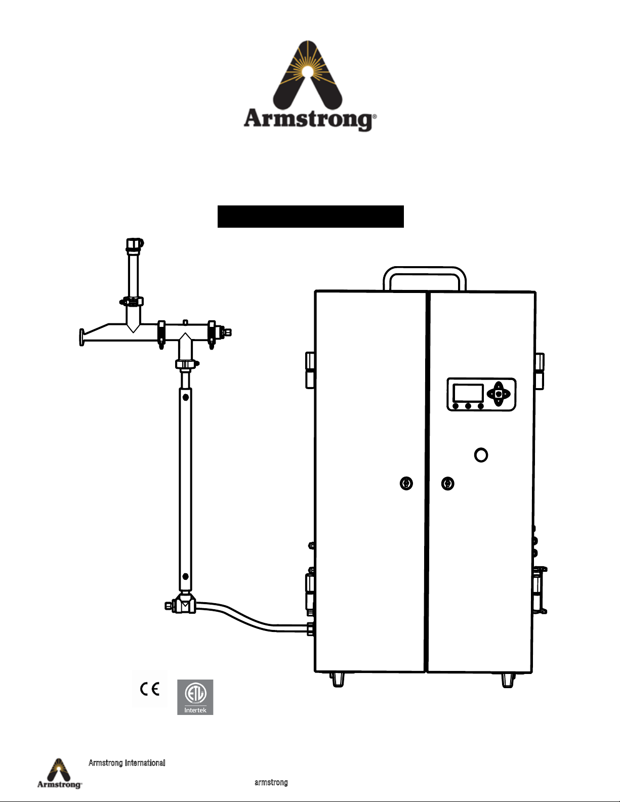
Steam QM-3 Calibration
Page 6 of 14
Calibrating the Temperature Sensors
Calibration #1: Calibrating T1, T2, T3 Temperature Sensors1
1. Turn off the Steam QM-3 and be sure it is cold. Check that the voltage switch is in the correct position for the voltage
being used.
2. Unplug the Temperature Sensor T1 from the QM-3.
3. Remove the Temperature Sensor T1 after unplugging it and plug it back in before install it in oil bath.
4. Install the oil bath on stable area close to the device.
5. Place the probe and the calibrated thermometer in the oil bath (as close as possible)
6. Set the oil bath at 80 °C
7. Wait that the oil bath is stabilized. And adjust its temperature to have 80 °C on the calibrated thermometer.
8. Turn on the QM-3.
9. On the Steam QM-3 display pad, press up and down arrows simultaneously to access the Debug sensor menu.
10. Write the value of T1 on the calibration certificate. If T1 is +- 0,7°C regarding the set point (80°C), the sensor is
considered as valid (go to the point 14). If not, you must adjust the sensor.
11. On the Steam QM-3 display pad, press left and right arrows simultaneously to access the code menu.
12. Enter 234 using the up and down arrows to change numbers and the left and right arrows to change the position to
access temperature calibration menu, and press OK.
13. Move the arrow to left of 80 °C on T1, press OK and wait for check mark.
14. Write 80 °C on the adjusted column of the calibration certificate.
15. Restart the procedure from point 5 with 140 °C instead of 80 °C.
16. Control the calibration with random temperature between 80 °C and 140 °C (restart the procedure from point 5) and
write it on the calibration certificate.
17. If the three calibrations are correct, check the valid mark on the calibration.
1 To reduce the time, part of calibration can be done simultaneously.
Recalibration Procedure
-> 0 0 0
x.xx
Code Menu
Access menu by pressing and
at same time. Navigate between digits by
pressing or .
Change value for digit by
pressing or .
Press «OK».
Turn off the steam to the Steam QM-3 and allow to cool
Version
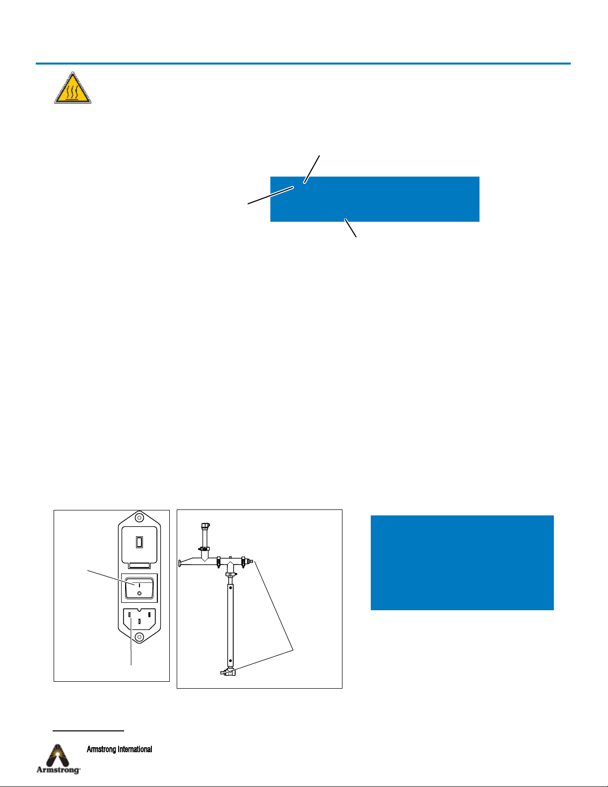
220
1
On/Off Switch
Power cord
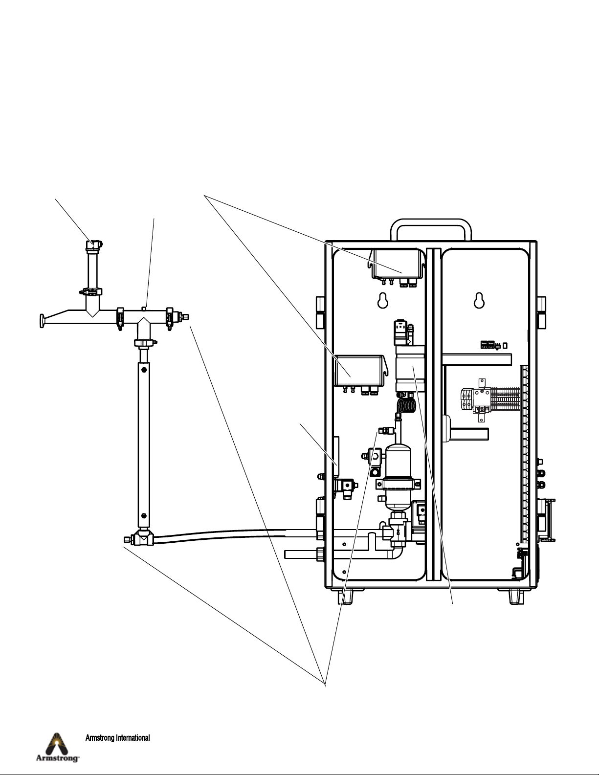
2
Temperature
transmitters
T1 and T2
Calibration T Sensor
T1 80 °C 140 °C
T2 80 °C 140 °C
T3 40 °C 80 °C
Temperature Calibration Menu 234