Aromat Cafe D4 Digital User manual
1
Powerplex Digital Range Service Manual
Service Manual
Powerplex Digital Range
(D4 Digital, D5 Digital)

2
Notice
Every effort has been made to ensure that the information contained in this document is up to
date and correct. However, neither the author, the publisher nor the manufacturer will accept
liability for any loss or damage caused resulting from any errors in or omissions of information
contained in this document.
This document may not be copied without the permission of DASS Manufacturing Ltd.
Document Change History
Issue Status Date
001 Document v1 Approved 08 Apr 2009
Conventions Used in this Document.
All instructions are given as viewed from the front of the machine unless otherwise stated.
Descriptions of the components referred to mostly match those used in the Illustrated
Parts Catalogue.
There are no bolts used in the construction of the machine. Hexagon headed screws are
referred to as Set Screws.
DASS Manufacturing Ltd.
SBC House,
Restmor Way,
Wallington,
Surrey, SM6 7AH,
United Kingdom.
Tel: +44 (0)20 8669 8012
Fax: +44 (0)20 8669 9529
Email: [email protected]
Web: www.aromat-uk.com
© Copyright 2009, DASS Manufacturing Ltd. All rights reserved
Document No: EN PPDI 03 001

3
Powerplex Digital Range Service Manual
Table of Contents
Notice 2
Conventions Used in this Document. 2
1 Introduction 5
1.1 Using this Manual 5
1.2 Understanding Fault Codes 6
1.3 Powerplex Digital Control Panels 6
1.4 Powerplex Digital Set Up Panel 7
1.5 Powerplex D4di Selection Switch Membrane 7
1.6 Powerplex D5di Selection Switch Membrane 7
1.7 Machine Supplied User Settings 7
1.8 Power Options 8
2 Engineer Configurable Settings 9
2.1 Making Changes 9
2.2 Putting the Powerplex Digital into Engineer Setup mode 9
2.3 The Engineer Menu Structure 9
2.4 Machine Supplied Settings 10
2.5 Engineer Setup Options 10
3 Obtaining Replacement Parts 12
3.1 Illustrated Parts Catalogue 12
3.2 Using Web Site 12
3.3 Obtaining User name and Password 12
3.4 Locating Part Illustration, Description and Number 12
3.5 On-line Parts Enquiry Form 12
3.6 Exploded View Assembly Drawing 12
4 Preparing the Powerplex Digital for Servicing 13
4.1 Preparing a Suitable Work Area 13
4.2 Noting Machine Settings 13
4.3 Removing the Casing Panels 14
4.4 Refitting the Casing Panels 14
4.5 Disconnecting / Reconnecting Power Supply Cabling 15
4.6 Disconnecting / Reconnecting Water Supply 16
4.7 Draining the Tank 16
5 Servicing Tank and Water Supply 17
5.1 Replacing the Water Inlet Valve 17
5.2 Replacing Water Outlet Valves 17
5.3 Setting Water Outlet Valve Flow Rate 18
5.4 Replacing Heating Elements 22
5.5 Setting Up Elements 23
5.6 Replacing a Temperature Control Thermostat 24
5.7 Adjusting the Temperature Control Thermostats 24
5.8 Replacing a Temperature Safety Thermostat 25
5.9 Replacing a Float Micro switch 26
5.10 Descaling the Tank 27
5.11 Cleaning Water Outlet Valves 28
5.12 Removing / Refitting Tank Assembly 29
5.13 Removing / Refitting a Tank Lid Assembly 30

4
6 Servicing Control Panel and Display 31
6.1 Removing / Refitting Control Panel Assembly 31
6.2 Replacing the Control PCB 31
6.3 Updating the PCB Processor Chip 32
7 Servicing the Cooler Unit 34
7.1 Removing / Refitting Cooler Unit 34
7.2 Checking Product Detect System 34
7.3 Replacing a Peristaltic Pump Motor 36
7.4 Adjusting a Peristaltic Pump 37
7.5 Servicing / Replacing a Heat Pump 39
7.6 Cleaning / Replacing a Cooling Fan 41
7.7 Cooler Unit Performance Testing 42
7.8 Checking the Cooler Unit Thermostat 43
7.9 Replacing Cooler Unit Door Magnets 43
7.10 Replacing Cooler Unit Door Gasket 44
7.11 Repairing Cooler Unit Door and Replacing / Updating Hinge 44
8 Servicing Dispenser Door Assembly 46
8.1 Replacing the Selection Switch Membrane 46
8.2 Replacing the Display Unit 46
8.3 Replacing Translation PCB 47
9 Servicing the Power Supply Unit 48
9.1 Extracting / Refitting PSU Assembly 48
9.2 Replacing the Relay and Regulator PCB 48
9.3 Replacing the Toroid PCB 49
9.4 Replacing a Toroid Transformer 50
9.5 Replacing the AC Connection PCB 51
9.6 Replacing the Coding PCB 52
9.7 Replacing an Element Selector Circuit Breaker 53
9.8 Replacing Mains Power Switch 53
9.9 Replacing Neon Lamp 54
9.10 Replacing Mains Voltage Selector Switch 54
9.11 Replacing a Cooling Fan 55
10 Technical Specifications 56
10.1 General Specifications 56
10.2 Main Looms Diagram 57
10.3 The Control PCB 58
10.4 Control Board LEDs 59
10.5 PSU Looms Diagram 60
10.6 Relay and Regulator PCB 61
10.7 AC Connection PCB 62
10.8 Toroid PCB 63
Appendices: 64
A Electrical Installation Instructions 64
B Recommended List of Tools required to Service the Powerplex 65
C Machine Settings Form 66
D Cleaning and Sanitising Instructions 67
Contact Details: 68
5
Powerplex Digital Range Service Manual
1 Introduction
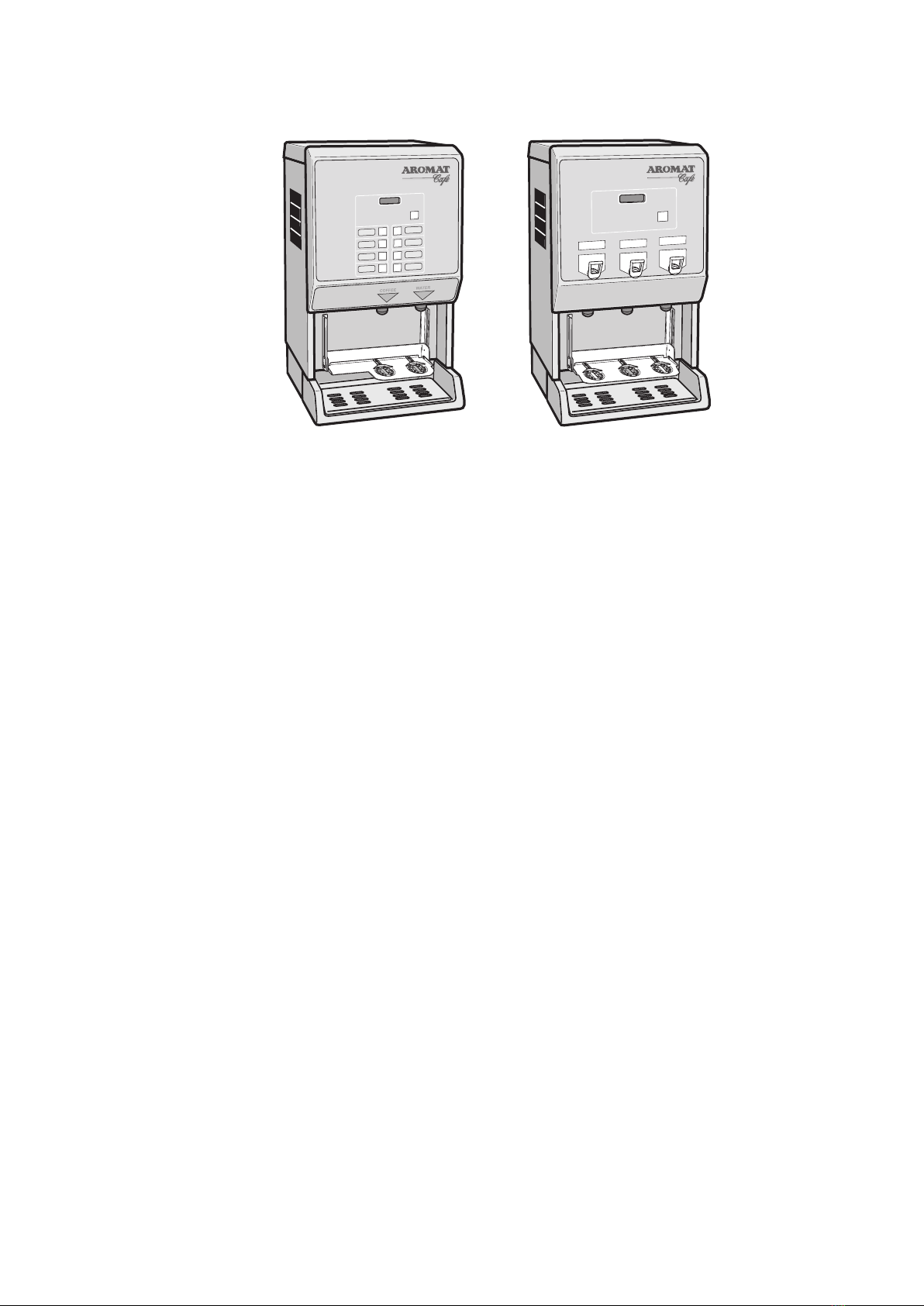
D4 Twin Nozzle Digital D5 Digital
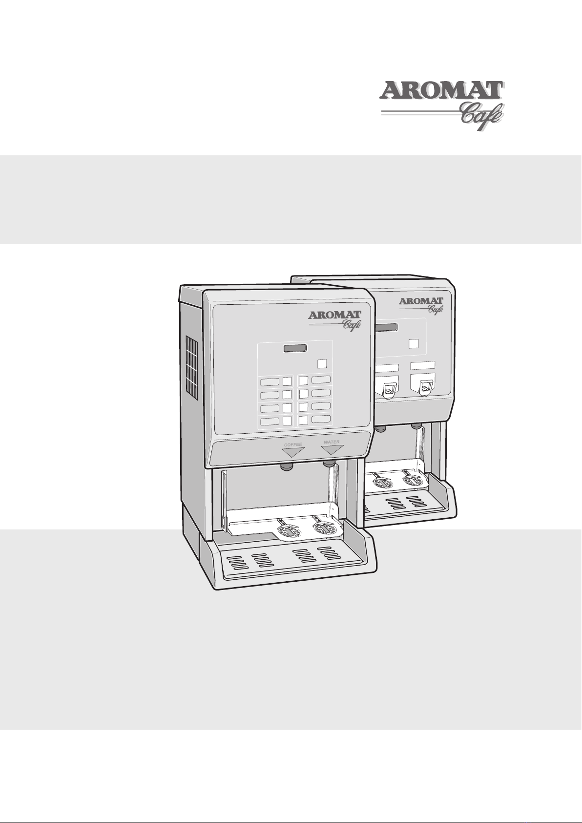
The Powerplex Digital Coffee Dispensers
The Powerplex digital range of coffee dispensers require minimal maintenance. The selection
of procedures listed in this document is based on the service requirement history of Powerplex
machines produced by Dass Manufacturing Limited since its launch.
For information on Powerplex variants, specifications and options, please refer to the
Powerplex Digital Set Up and User Guide. This document may be downloaded from the
Aromat Technical Web site - www.aromatec.co.uk. A Username and Password will be required;
contact Dass Manufacturing Limited to register.
To attain the highest levels of quality and reliability, the Powerplex digital range has undergone
and will continue to undergo continuous design development during its life cycle. This
document will therefore be updated regularly to reflect any changes.
WARNING: Before replacing any major component, it is essential that the machine is
isolated from both the mains power and mains water supplies.
1.1 Using this Manual
This manual describes the processes for the machine’s operation, how to obtain
replacement parts and instructions for carrying out the most probable maintenance
procedures. To avoid repeating basic tasks, the document has been sectioned to enable
the reader to extract the relevant sub-sections for reference when working on site.
It will be updated on a regular basis and will not be published in hard copy, although a
printable pdf version will be available for downloading from the DASS Technical Web Site.
Before carrying out any maintenance on the machine, the service engineer should consult
the web site and either download the latest pdf version of the entire document or print off
the relevant individual web pages.
To identify the parts referred to in this manual, you may find it useful to view the
respective machine’s Illustrated Parts Catalogue, available from the web site.
Any comments or advice from service engineers that would improve the document would
be welcomed. Please email any comments to [email protected].
6
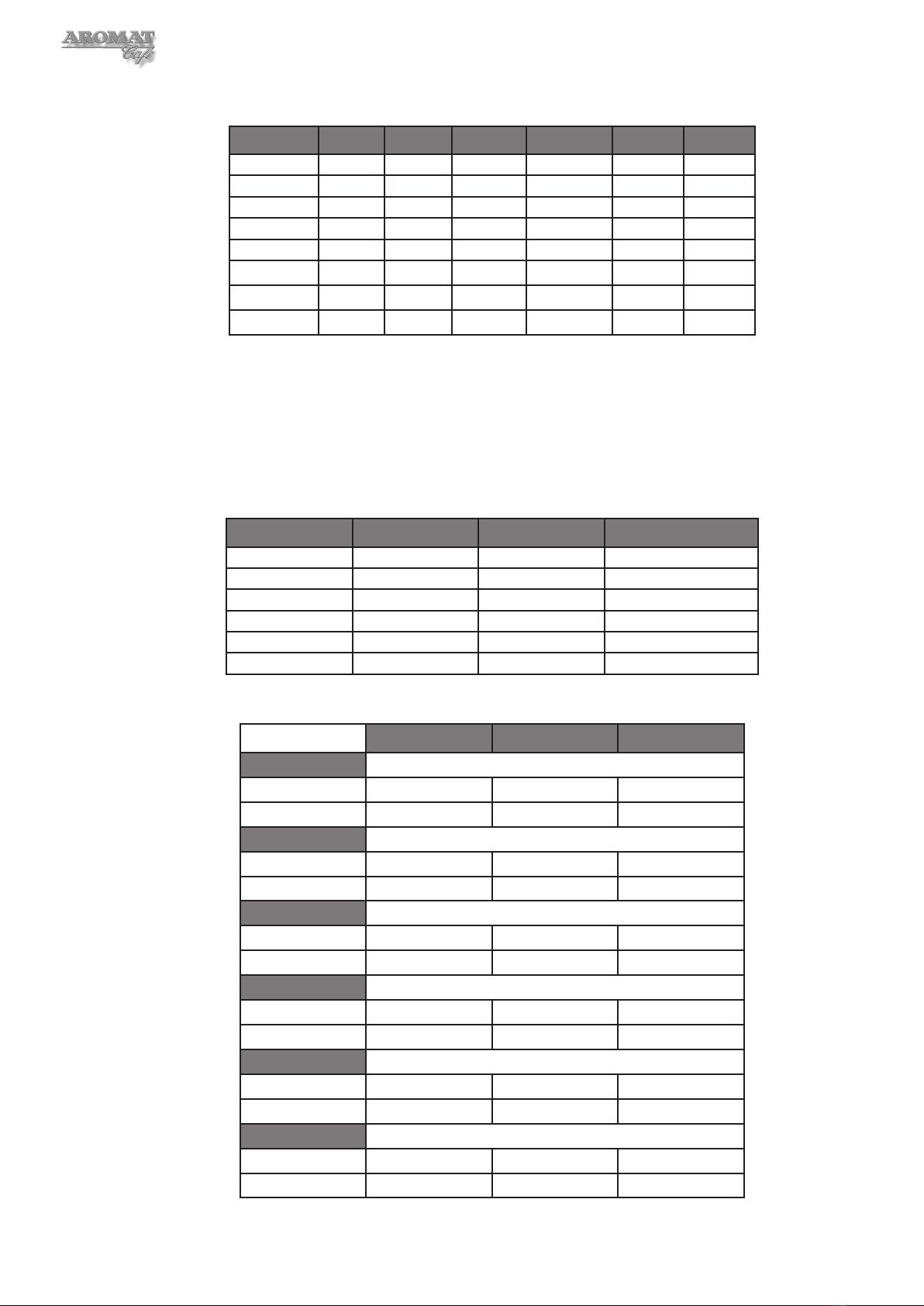
1.2 Understanding Fault Codes
The table below describes the Fault Codes displayed on the Powerplex Digital
Dispensers:
Fault Description / Cause
Overflow Float Too much water in tank
Float Fault Logical fault. Overflow detected but insufficient water in tank.
Possible stuck float or faulty switch.
Thermostat Trip Thermostat has detected boiler overheat. Possible faulty thermostat.
Lack of Water During normal operation after machine has filled for the first time, the
inlet valve has been open for more than 5 minutes. Possible main
water valve closed, low water pressure or faulty inlet valve.
Lack of Water #1 The initial water fill from empty has taken longer than 15 minutes.
Possible inadequate water flow or pressure.
Refer to the Troubleshooting Section in the Powerplex Digital User Guides.
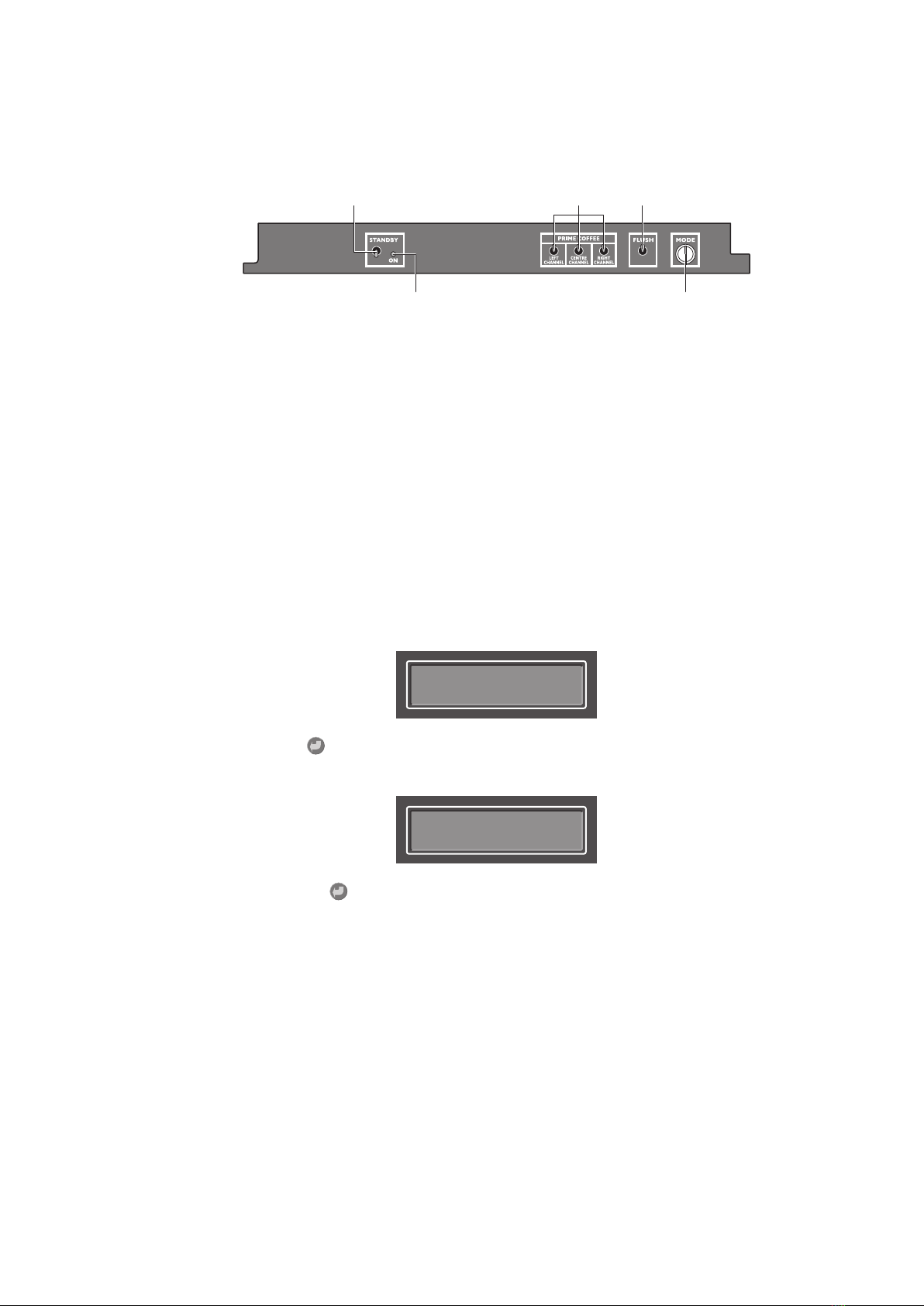
1.3 Powerplex Digital Control Panels
The Powerplex digital machines are managed using the switches on the Set Up Panel
located above the Cooler Unit door and the display and the buttons on the Selection
Switch Membrane on the front of the Dispenser Door Assembly.
Turning the Mode Keyswitch will put the machine into SET UP MODE.
SET UP MODE
Press Selection
The SET UP MODE display:
The Product Selection Button setting options are:
• Enabled or Disabled
• Method (Preset or Held On)
• Type (Coffee or Water)
• Speed (1 or 2)
• Volume (of dispense)
• Channel (1, 2 or 3)
• Strength (ratio of water to concentrate)
The Product Faucet setting options are:
• Enabled or Disabled
• Strength (ratio of water to concentrate)
Scroll through the options by pressing the Enter button.
The Hidden Buttons on the Door Membrane are used to navigate the Menus in both
SET UP MODE and ENGINEER MODE.
7
Powerplex Digital Range Service Manual
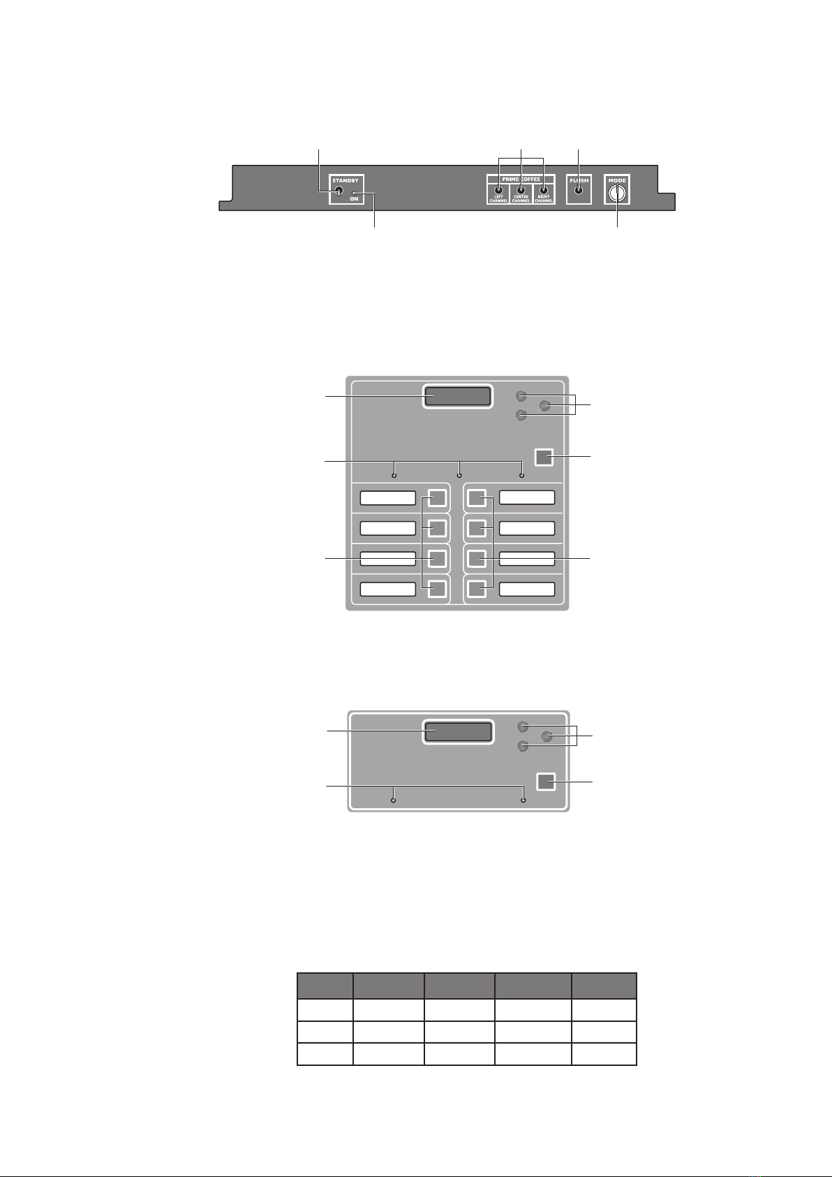
1.4 Powerplex Digital Set Up Panel
Standby
LED
Mode
Keyswitch
Standby
Switch
Flush
Switch
Prime
Switches
The functions of the switches are described in the Powerplex Digital Dispenser User
Guide which may be downloaded from the web site.
1.5 Powerplex D4di Selection Switch Membrane
PRODUCT 1 EMPTY PRODUCT 2 EMPTYPRODUCT 2 EMPTY
Digital Display
STOP Button
Product Selection
Buttons 1, 2, 3, 4
Product Selection
Buttons 5, 6, 7, 8
Hidden Buttons
Product Empty LEDs
The hidden buttons are used to navigate through the display menus and make selections.
1.6 Powerplex D5di Selection Switch Membrane
PRODUCT 1 EMPTY PRODUCT 2 EMPTY
Digital Display
STOP Button
Hidden Buttons
Product Empty LEDs
The hidden buttons are used to navigate through the display menus and make selections.
1.7 Machine Supplied User Settings
Machines are configured in the factory with the following user settings:
Note: These settings may have been changed by the Installation Engineer.
Powerplex D5di
Faucet Method Type Strength Channel
LH Held ON Product 1 40:1 1
Centre Held ON Product 2 40:1 3
RH Held ON Water - -
8
Powerplex D4di
Button No. Speed Method Type Volume Strength Channel
1 1 Preset Coffee 55 40:1 1
2 2 Preset Coffee 55 40:1 1
3 1 Preset Coffee 55 40:1 2
4 2 Preset Coffee 55 40:1 2
5 1 Preset Coffee 55 40:1 3
6 2 Preset Coffee 55 40:1 3
7 1 Preset Water 55 - -
8 1 Held ON Water - - -
The strength ratio 40:1 means 1 part of coffee concentrate is added to 40 parts of water.
1.8 Power Options
Every machine leaving the factory is designed to provide a range of power options,
selectable at installation.
Three phase
Volts per phase Amps per phase kW per phase Total heating power
110 5.26 0.58 1.74 kW
115 5.5 0.63 1.9 kW
120 5.74 0.69 2.07 kW
220 10.53 2.32 6.96 kW
230 10.98 2.53 7.59 kW
240 11.5 2.75 8.25 kW
Single phase
1 Element 2 Elements 3 Elements
110V ac
Amps 5.26 10.52 15.78
Heating Power 0.58 kW 1.16 kW 1.74 kW
115V ac
Amps 5.5 11.0 16.5
Heating Power 0.63 kW 1.26 kW 1.89 kW
120V ac
Amps 5.75 11.5 17.25
Heating Power 0.69 kW 1.38 kW 2.07 kW
220V ac
Amps 10.53 21.06 31.59
Heating Power 2.32 kW 4.64 kW 6.96 kW
230V ac
Amps 10.98 21.96 32.94
Heating Power 2.53 kW 5.06 kW 7.59 kW
240V ac
Amps 11.5 23.0 34.5
Heating Power 2.75 kW 5.5 kW 8.25 kW
9
Powerplex Digital Range Service Manual
2 Engineer Configurable Settings
It is necessary to open the cooler unit door to access the Control Panel switches.
Standby
LED
Mode
Keyswitch
Standby
Switch
Flush
Switch
Prime
Switches
The Control Panel for the Powerplex Digital Range
2.1 Making Changes
DASS Manufacturing Ltd. will not accept liability for any damage or losses caused as a
direct result of any changes made to the machine by the service engineer when carrying
out any of the procedures described in this manual. All replacement parts used in the
Powerplex dispenser should be approved by DASS Manufacturing Ltd.
2.2 Putting the Powerplex Digital into Engineer Setup mode
1 Turn the Mode Change Keyswitch to put the machine into SET UP MODE.
2 Operate the LEFT CHANNEL Prime Switch and then the CENTRE CHANNEL
Prime Switch; the following will display:
ENGINEER SETUP
press
ENTER
3 Press the Enter button on the Selection Switch Membrane. The display will
change to something similar to:
Machine Type
D4 3 product
Pressing the Enter button will scroll though the menu back to the SET UP
MODE display. Turn the Mode Change Keyswitch to reset to dispense mode.
2.3 The Engineer Menu Structure
In ENGINEER SETUP mode, the following settings may be changed:
• Machine Type
• Enable / Disable Coffee
• Enable / Disable Water
• Pump Speed Offset
• Enable / Disable Product Sensors
• Enable / Disable Leak Detect
• Elements on with Inlets - YES or NO
• Elements on with Selection - YES or NO
10
Note: Setting Elements on with Inlets = YES allows heating of water during filling by
overriding the thermostat.
Note: Setting Elements on with Selection = YES allows heating of water during
dispensing by overriding the thermostat.
2.4 Machine Supplied Settings
The machine was configured in the factory with the following Engineer Mode settings:
Machine Type D4 3 product
Coffee Enabled
Water Enabled
Product Sensors Enabled
Leak Detect Enabled
Elements on with Inlets = YES
Elements on with Selection = YES
Note: Peris Pump Speed offsets will have been configured correctly for the machine in
the factory and will only need to be adjusted if a pump has been replaced.
Note: These settings may have been changed by the Installation Engineer to suit the
customer’s requirements.
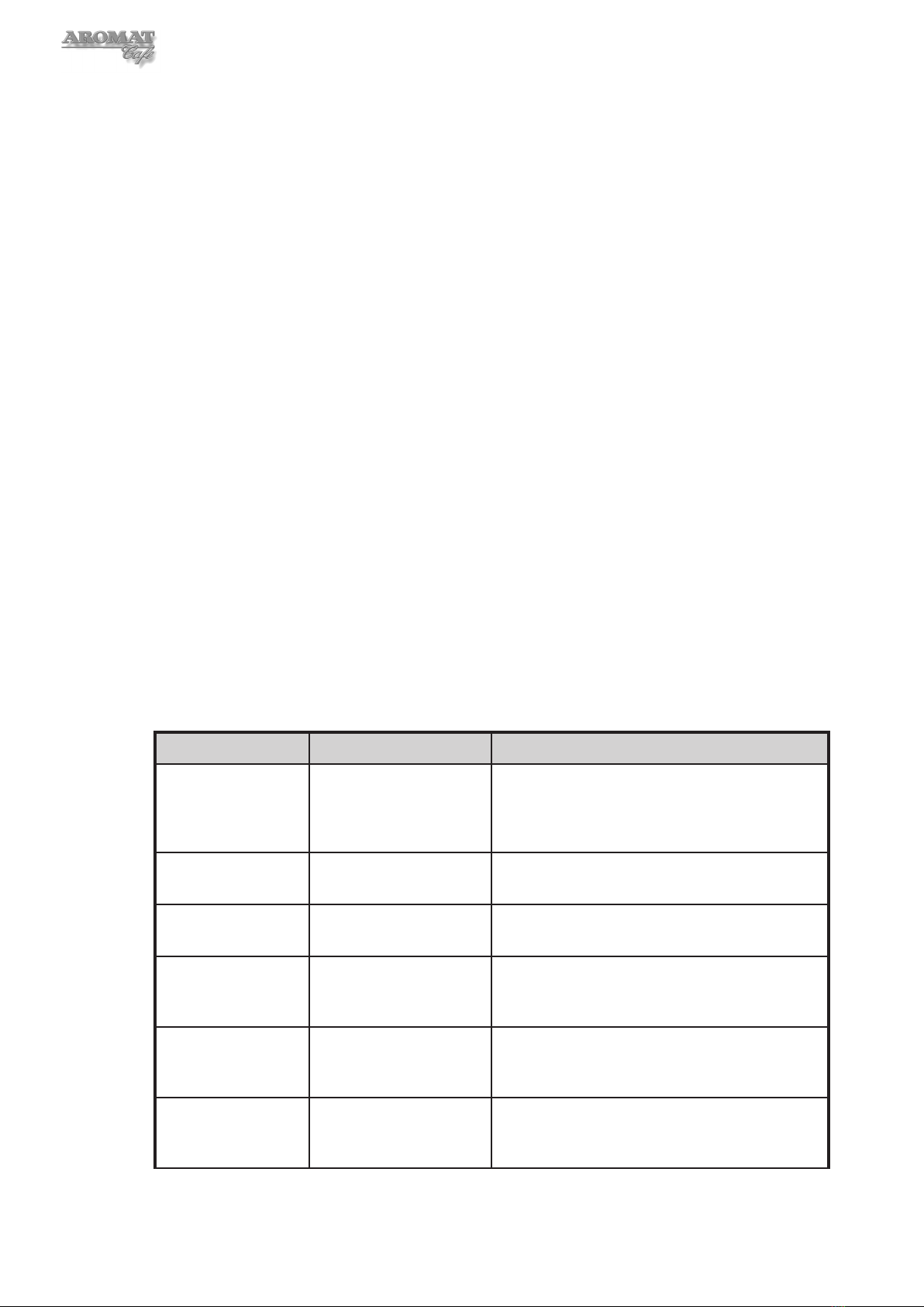
2.5 Engineer Setup Options
Changes are made using the Up, Down and Enter buttons on the Control Panel.
The table below shows the options available and describes the Engineer Setup menu
functions:
Menu Item Options Description
Machine Type D4 1 product
D4 2 product
D4 3 product
D5
The D4 machine is supplied with three channels
and can be set to dispense up to three different
products. The D5 can only dispense two product
types.
Coffee Enabled
Disabled
Set to Enabled for normal use. Set to Disabled
when adjusting outlet valves.
Water Disabled
Enabled
Set to Enabled for normal use. Set to Disabled
when calibrating the peristaltic pump offset.
Peris 1 Speed
offset =
- nn to + nn Set correctly when machine left the factory. Only
needs to be adjusted at annual service or if a
new pump is installed.
Peris 2 Speed
offset =
- nn to + nn Set correctly when machine left the factory. Only
needs to be adjusted at annual service or if a
new pump is installed.
Peris 3 Speed
offset =
- nn to + nn Set correctly when machine left the factory. Only
needs to be adjusted at annual service or if a
new pump is installed.

11
Powerplex Digital Range Service Manual
Menu Item Options Description
Product Sensor Enabled
Disabled
Usually Enabled when machine is in use.
Disabled to avoid wasting product when
calibrating and as a temporary fix if sensors fail.
Leak Detect Enabled
Disabled
Normally Enabled. Will show Fault if a leak is
detected (see Section 1.2 Understanding Fault
Codes). If the machine is dormant for long
periods of time, it may be Disabled.
Elements on with
Inlets =
YES
NO
Selecting YES allows heating of water during
filling. Overides the thermostat..
Elements on with
Selection =
YES
NO
Selecting YES allows heating of water during
dispensing. Overides the thermostat.
SET UP MODE
Press Selection
Reverts back to normal operators Set Up Mode.
Turn Keyswitch to place machine into normal
user mode.
12
3 Obtaining Replacement Parts
3.1 Illustrated Parts Catalogue
A printable Illustrated Parts Catalogue may be downloaded from the Technical Web site.
3.2 Using Web Site
To access the technical web site go to www.aromat-info.com and select
Technical Documents. This will take you to the Technical Centre which is in both
English and German. A Username and Password is required to access the site.
3.3 Obtaining User name and Password
Complete and send the on-line Registration Form or send an email to:
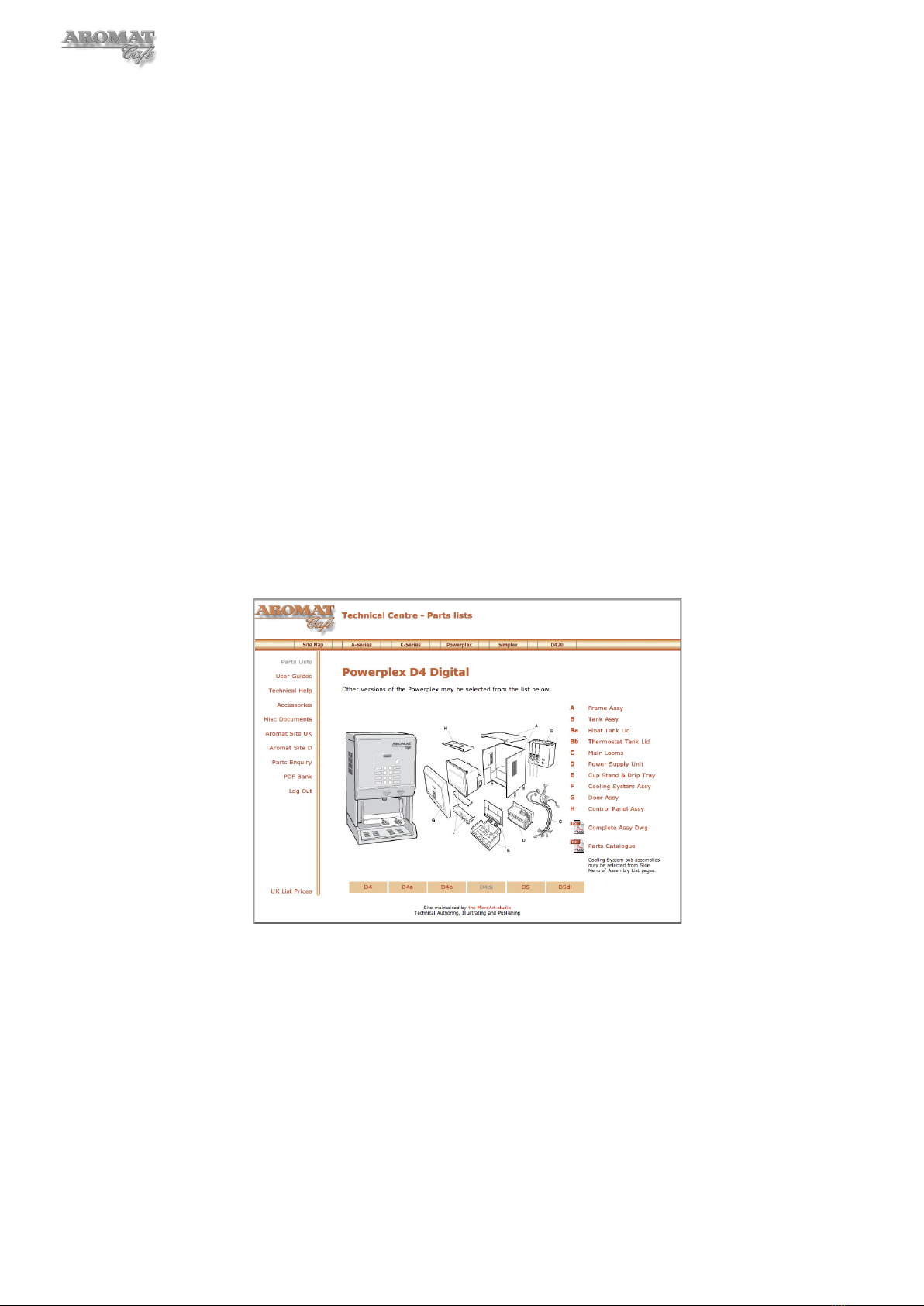
3.4 Locating Part Illustration, Description and Number
Select Parts Lists from the left menu and then Powerplex at the top of the Navigation
page. On the Powerplex Range page, click on the model for the relevant Parts Lists
Overview page. Clicking on an assembly image will open a new window with an
annotated exploded view of that assembly. Clicking on the assembly menu will take you
to the relevant section in the parts list.
Typical Powerplex Digital Parts Lists Overview Page
3.5 On-line Parts Enquiry Form
Having located a part, selecting Parts Enquiry from the left hand menu will open
a new window with an on-line form. Complete the form and press SEND. A DASS
representative will get back to you with prices and availability, as soon as possible.
3.6 Exploded View Assembly Drawing
A printable composite exploded view of the Powerplex Digital assembly is also available
from the Aromat Technical Web site on the relevant Parts Lists Overview page.

13
Powerplex Digital Range Service Manual
4 Preparing the Powerplex Digital for Servicing
WARNING: To avoid electric shock, when the casing panels are being removed, the
dispenser MUST be isolated from the mains power supply.
Note: Unless essential for any work being carried out, we recommend that the valve for the
mains water service to the machine also be closed before servicing the machine.
4.1 Preparing a Suitable Work Area
Many components of the Powerplex Digital Coffee Dispenser can be serviced or replaced
in-situ but where main assemblies need to be removed from the machine, we recommend
that a work area or temporary mobile work bench be set up adjacent to the machine.
Ideally, this work area should not be less than 10 square feet (1 square metre).
For most operations, only the top panel needs to be removed. Space is required for
temporary storage of any panels removed.
Ensure that all of the tools required are to hand before undertaking any major
disassembling.
4.2 Noting Machine Settings
Before undertaking any maintenance on the Powerplex, noting down all of the current
user and engineering mode settings will enable you to return the machine to service
exactly as the original settings.
Note: It may be necessary to change the dispense volume settings for one or more of
the product selection buttons when undertaking some maintenance procedures. These
may need to be reset with the customer present on completion of the work.
The User Settings to note for each Product Select Button or Faucet are:
• Selection (Enabled or Disabled).
• Dispense Speed (1 or 2) - D4di only.
• Selection Method (Preset or Held on) - D4di only.
• Selection Type (Coffee or Water) - D4di only.
• Dispense Volume (2 or 3 digit number) - D4di only.
• Selection Strength (water:coffee ratio).
• Channel (1, 2 or 3 - depends on Product Setting) - D4di only.
The Engineer Setup mode settings to note are:
• Machine Type
• Pump Speed Offset.
• Product Sensor (Enabled or Disabled)
• Elements on with Inlets (Yes or No)
• Elements on with Selection (Yes or No)
• Leak Detect (Enabled or Disabled).
A Machine Settings Form is included in Appendix B of this manual; also available as a
printable pdf document from the Aromat technical web site in the User Guides section.

14
4.3 Removing the Casing Panels
WARNING: Before removing any of the Casing Panels the machine MUST be
isolated from the mains power supply.
Note: The machine should only be powered ON with the panels removed if the engineer
can satisfy himself that it is safe to do so.
For many of the servicing operations, only the Top Panel needs to be removed.
Tools required:
No. 2 Pozidrive Screwdriver
To remove the Casing Panels:
1 Power OFF and isolate the machine from the mains power supply.
2 To remove the Top Panel, open the Dispenser Unit Door and remove the two M4
x 6mm panhead screws securing the Top Panel to the Control PCB Mounting
Plate. Lift up the panel to clear the switch panel, slide towards the back of the
machine and lift off.
3 To remove a Side Panel Extension, loosen the three M4 x 6mm screws two M4
x 8mm screws securing it to the Side Frame and bottom lip of the Side Panel.
Holding each end, carefully ease out the Side Panel Extension.
4 To remove the Cup Stand Assembly, fold up the Cup Stand and undo the four
M4 x 12mm screws securing the Lower Front Panel to the Inner Side Panels.
Lift the complete assembly out.
5 To remove the Door Assembly, first disconnect the looms at the Control Panel
PCB. Disconnect the Door Earth Wire from the stud on the door. Support the
Door Assembly and remove the m4 x 20mm Panhead screws securing the Side
Panel Hinge Blocks to the LH Side Panel. The complete Door Assembly may
now be lifted away.
6 To remove a Side Panel Assembly, at the back of the machine, remove the three
lower M4 x 6mm panhead screws securing the Side Panel to the Membrane
Panel. Loosen the top screw. Completely remove the three screws already
loosened to remove the Side Panel Extension and whilst holding the panel in
position with one hand, completely remove the top screw securing the Side Panel
at the back. Ease the Side Panel out at the back to clear the Membrane Panel
and slide the panel forward. The Side Panel Assembly can now be lifted away
from the machine.
4.4 Refitting the Casing Panels
WARNING: Before refitting any of the Casing Panels the machine MUST be
isolated from the mains power supply.
Tools required:
No. 2 Pozidrive Screwdriver
1 Power OFF and isolate the machine from the mains power supply.
2 First refit the Side Panel Assemblies by reversing the instructions in Section 4.3.
Leave the three lower panel fixings loose to facilitate installing the Lower Side
Panels.

15
Powerplex Digital Range Service Manual
3 Refit the Lower Side Panels by sliding the panels into position and tightening the
three screws securing it to the Side Frame and bottom lip of the Side Panel.
4 Refit the Cup Stand Assembly by reversing the instructions in Section 4.3.
5 Refit the Door Assembly by reversing the instruction in Section 4.3.
6 Refit the Top Panel by reversing the instruction in Section 4.3.
4.5 Disconnecting / Reconnecting Power Supply Cabling
Note: This procedure MUST be carried out by a qualified Electrician. Refer to Section
1.8 for Power Option connection details.
WARNING: The Mains Power Supply MUST be switched OFF and the cable
unplugged or disconnected from the supply.
Tools required:
No. 2 Pozidrive Screwdriver
7mm Spanner
Terminal Screwdriver
Gland Spanner
1 Power OFF and isolate the machine from the Mains Power Supply.
2 Undo and remove the four M4 x 10mm screws securing the PSU Cover Panel to
the PSU Housing.
3 Disconnect the Mains power cables from the Terminal Block and the Earth cable
from the Earth Connection stud.
4 If necessary, undo the cable gland-securing nut and pull the cable out through the
Gland Plate and PSU Housing base plate.
Reconnect the Power Supply by reversing the above instructions. Refer to the Electrical
Installation Instructions displayed on the inside of the PSU Cover Panel a copy of
which is shown in Appendix A of this document.
WARNING: Serious damage will be caused if the Mains Voltage Selector
Switch located beneath the Element Selector Circuit Breakers is not set to the
correct voltage. For Connection Details Refer to Section 1.8.

16
4.6 Disconnecting / Reconnecting Water Supply
Note: When the Powerplex is powered OFF, water will not flow through the inlet valve.
Tools required:
1 1/8” AF Spanner
Suitable Bucket or Container
To disconnect the dispenser from the Mains Water Supply:
1 Ensure that the mains valve is closed.
2 Place a bucket or suitable container beneath the mains valve.
3 Disconnect the flexible inlet connector pipe from the mains valve and allow the
water in the hose to run into the container. Retain the fibre washer.
4 If necessary, disconnect the flexible inlet connector pipe from the Valve mounted
on the Water Inlet Valve Plate, retaining the fibre washer.
The water supply is reconnected by reversing the instructions above.
4.7 Draining the Tank
WARNING: Water in the tank may scald.
Note: When the Powerplex Dispenser is powered OFF, water will not flow through the
Water Inlet Valve. DO NOT shut off the water at the supply valve and leave the machine
powered ON, as this could damage the Water Inlet Valve.
Note: The tank capacity is 8 US gallons (30 litres)
Tools required:
No. 2 Pozidrive Screwdriver
Min 200 ml container
Large bucket
To drain the tank:
1 Power OFF and isolate the machine from the Mains Power Supply.
2 Disconnect the dispenser from the Mains Water Supply as described above in
Section 4.6.
3 Remove the Cup Stand Assembly, as described in Section 4.3.
4 The Drain Hose is connected to the bottom right hand of the tank. Carefully
extract the hose and clamp.
5 Place the end of the Drain Hose over the bucket (or drain if available).
6 Open the Drain Hose Clamp to allow water to pass. Close and reopen the clamp
as necessary until the tank is empty
7 Remove the plastic ‘U’ clip from the top of the Inlet Valve.
8 Pinch the Inlet Valve Tank Hose between thumb and forefinger and pull the plastic
angled connector from the top of the Inlet Valve.
9 Holding the pinched hose and connector over a minimum 200 ml container, release
the hose and allow the water to run out.

17
Powerplex Digital Range Service Manual
5 Servicing Tank and Water Supply
It is not necessary to remove the tank to undertake maintenance of the Powerplex’s water
supply components. However, instructions for removing / replacing the tank have been
included at the end of this section.
5.1 Replacing the Water Inlet Valve
The Water Inlet Valve is located inside and fitted onto the Water Inlet Valve Plate,
mounted behind the Cup Stand Assembly. It is not necessary to drain the water tank to
replace the Water Inlet Valve.
Tools required:
1 1/8” AF Spanner
No. 2 Pozidrive Screwdriver 12 inch
No. 2 pozidrive Screwdriver Stubby
Side Cutting Pliers
Hose Clip
1 Power OFF the machine.
2 Disconnect from the mains water supply as described in Section 4.6.
3 Isolate the machine from the Mains Power Supply.
4 Remove the Cup Stand Assembly as described in Section 4.3.
5 Drain the Inlet Valve Tank Hose as described in Section 4.7 - steps 7 & 9.
6 Undo the two screws securing the valve to the Water Inlet Valve Plate and extract
the Water Inlet Valve.
7 After noting positions, carefully remove the cable connectors.
8 Cut the hose clip and disconnect the Water Inlet Hose to the tank.
9 Fit the new valve by reversing the above procedure.
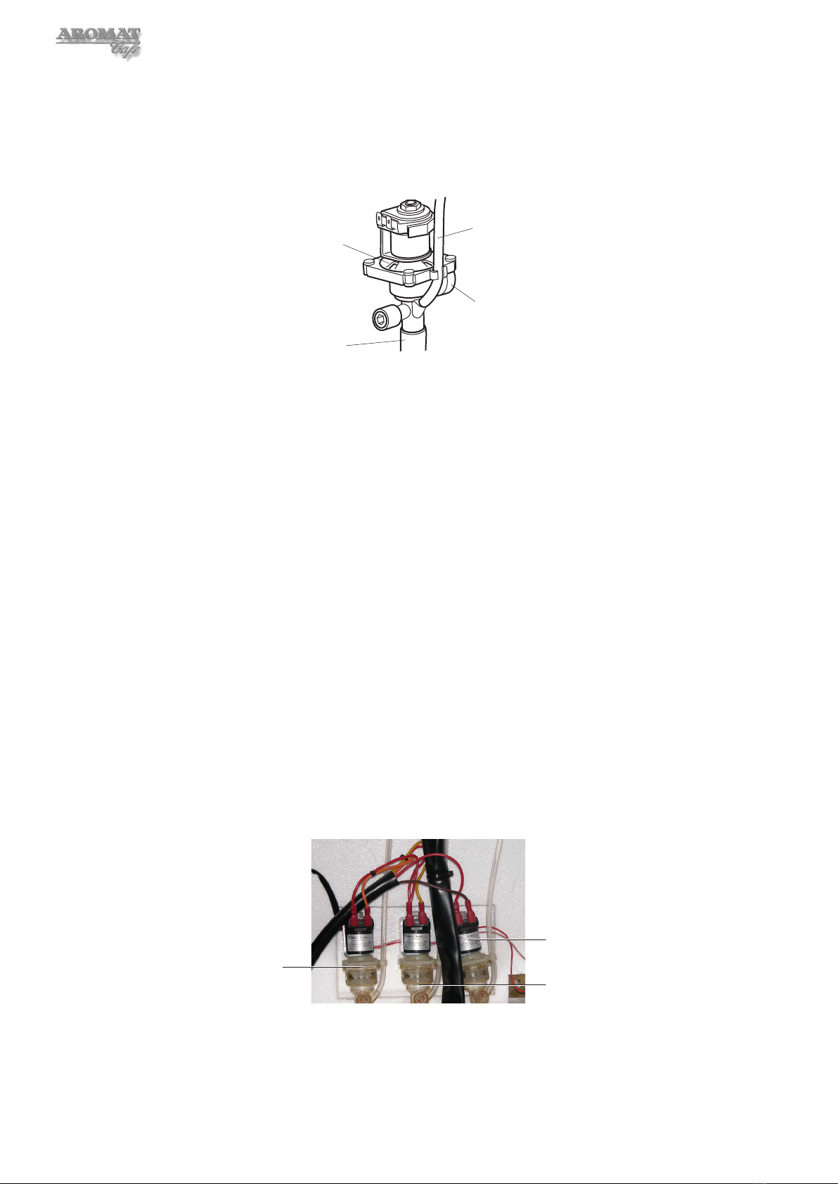
5.2 Replacing Water Outlet Valves
There are three Water Outlet Valves. One valve is used to dispense hot water only; the
other two are for dispensing water for coffee.
Left Valve
Right Valve
Centre Valve
Tools required:
No. 2 Pozidrive Screwdriver 12 inch
To replace a Water Outlet Valve:
1 Power OFF and isolate the machine from the Mains Power Supply.
18
2 Remove the Cooler Unit as described in Section 7.1.
3 Drain the tank as described in Section 4.7 - steps 2 to 5.
4 Open the hose clamp to allow water to pass. Close and reopen the clamp as
necessary until the level of the water in the tank is below the Valve Inlet.
Valve Vent Tube
Outlet Tube
Valve Inlet
Valve Body
4 Disconnect the Valve Vent Tube.
5 Mark cables and disconnect the wiring to the valve motor.
6 Slightly rotate and carefully slide the valve out of the Boiler Seal, removing the
valve with the Outlet Tube still connected.
7 Disconnect the Outlet Tube.
8 Fit the Outlet Tube to the new valve and carefully push the new valve into the
Boiler Seal.
9 Reconnect the Valve Vent Tube.
Note: The flow rate for the new valve now has to be set. To do this, the machine must
be powered ON, the tank refilled and the water brought up to the maximum operating
temperature. Do not refit the Cooler Unit yet.
5.3 Setting Water Outlet Valve Flow Rate
The Powerplex digital dispenser has three 12 mm valves. The Left and Centre Valves are
for dispensing water for the product and the Right Valve is for hot water only. The flow
rate for all three valves will have been set to 5 litres per minute in the factory. This setting
is important in establishing the concentrate ratios for the left and centre channels.
Note: The machine must be powered ON, the tank filled and brought up to maximum
operating temperature of 95°C (203°F) before setting the flow rate.
Left Valve
Right Valve
Centre Valve
Note: We recommend that both the Left and Centre Valves are adjusted together. This
procedure may require changing the speed and channel settings and we recommend that
the original settings are noted down as described in Section 4.2.

19
Powerplex Digital Range Service Manual
Tools required:
No. 2 Pozidrive Screwdriver
1 litre calibrated container
Timer with second hand
8mm hexagonal key (or 8mm flat end screwdriver)
To adjust the flow rate for the ‘water for coffee’ Outlet Valves:
1 If installed, remove the Cooler Unit as described in Section 7.1, and refit
connectors to the Control PCB.
2 Turn the Mode Change keyswitch to put the machine into SET UP MODE.
3 Put the machine into Engineer Setup by pressing down the LEFT CHANNEL and
CENTRE CHANNEL Prime Switches.
On D4di Dispensers:
4 Press the Enter button to scroll down until Machine Type is displayed. Select
D4 3 Product.
5 Press the Enter button and scroll down until Coffee Enabled is displayed then
press the Down button to disable coffee.
6 Press the Enter button and scroll down until Product Sensors is displayed then
press the Down button to disable product sensors.
7 Press the Enter button to scroll through the menu until SET UP MODE is displayed
again.
8 Press Dispense Selection button 1 and set to:
Selection 1 = Enabled
Speed = 1
Selection 1 = Preset
Selection 1 = TYPE Coffee
Volume = 55
Channel = 1
9 Press Dispense Selection button 2 and set to:
Selection 2 = Enabled
Speed = 2
Selection 2 = Preset
Selection 2 = TYPE Coffee
Volume = 55
Channel = 2
10 Press Dispense Selection button 3 and set to:
Selection 3 = Enabled
Speed = 1
Selection 3 = Preset
Selection 3 = TYPE Water
Volume = 55
Channel = 3
11 Scroll through the menu until SET UP MODE is displayed again and turn the
Mode Change keyswitch back to normal dispense mode.
12 Place the calibrated container under the Coffee Dispense Nozzle.
13 Ensure the water in the tank is at maximum operating temperature by checking
that the LED on the PCB is not lit and press Dispense Selection button 1.
14 Check the level in the container. It should be at the 500 ml mark.

20
15 If necessary, adjust the Left Valve by turning the screw anti-clockwise to increase
the flow and clockwise to decrease the flow. One full turn of the screw will change
the volume by approximately 50 ml.
Adjustment Screw
Valve Body
16 Carefully dispose of the water and repeat the operation until the level in the
container is 500 ml. Once the Left Valve is set, DO NOT READJUST.
17 Ensure the water in the tank is at maximum operating temperature by checking
that the LED on the PCB is not lit and press Dispense Selection button 2.
18 Check the level in the container. It should be at the 1000 ml mark.
19 Adjust the Centre Valve by turning the screw one quarter of a turn each time. Turn
anti-clockwise to increase the flow and clockwise to decrease the flow.
20 Carefully dispose of the water and repeat the operation until the level in the
container is 1000 ml.
21 When correctly set, carefully dispose of the water.
22 Ensure the water in the tank is at maximum operating temperature by checking
that the LED on the PCB is not lit and press Dispense Selection button 3.
23 Check the level in the container. It should be at the 750 ml mark.
24 Dispose of the water, refit Cooler Unit and reset Dispense Selection buttons to
the customer’s settings as noted.
On D5di Dispensers:
4 Press the Enter button to scroll down until Machine Type is displayed. Select
D4 3 Product..
5 Press the Enter button and scroll down until Coffee Enabled is displayed then
press the Down button to disable coffee.
6 Press the Enter button and scroll down until Product Sensors is displayed then
press the Down button to disable product sensors.
7 Press the Enter button to scroll through the menu until SET UP MODE is displayed
again.
8 Operate the Left Faucet and set to:
Selection 8 = Enabled
Speed = 1
Selection 8 = Preset
Selection 8 = TYPE Coffee
Volume = 55
Channel = 1
9 Operate the Centre Faucet and set to:
Selection 7 = Enabled
Speed = 1
Selection 7 = Preset
This manual suits for next models
1
Table of contents


