Aros 12k55enua User manual


RPS SpA
via Somalia, 20
20032 Cormano (MI)
Tel. +39 02 66327.1
Fax +39 02 66327.231
www.aros-solar.com

1
CONTENTS
PRESENTATION .................................................................................................... 3
CONFIGURATION.................................................................................................. 4
Overview .......................................................................................................... 4
Basic interactions............................................................................................... 7
Description of the Menu ...................................................................................... 8
Measurements ................................................................................................ 8
Historical data ...............................................................................................11
Configuration.................................................................................................15
Alarms and statuses .......................................................................................28
Actions .........................................................................................................29
Information ...................................................................................................30
TECHNICAL DETAILS............................................................................................32
Technical specifications...................................................................................32
Compatibility Protocols ...................................................................................32
software version ............................................................................................32

2

3
PRESENTATION
1. Touch screen
2. USB port
3. Ethernet port
1
2
3

4
CONFIGURATION
Overview
Sirio Central inverters have a new man-machine interface (MMI) as standard, consisting of a colour
LCD Touch panel. The characteristics and the quantity of information enrich the experience of user
interaction with the solar inverter.
Everything can be done with just a touch.
When the inverter is started up for the first time after commissioning, a screen appears asking you
choose the country where the inverter is installed:
Press the arrows on the right to scroll between the countries currently managed. Once the choice has
been made, simply touch the image of the Earth to proceed with the configuration:
You can confirm or cancel your choice going back to the previous screen.

5
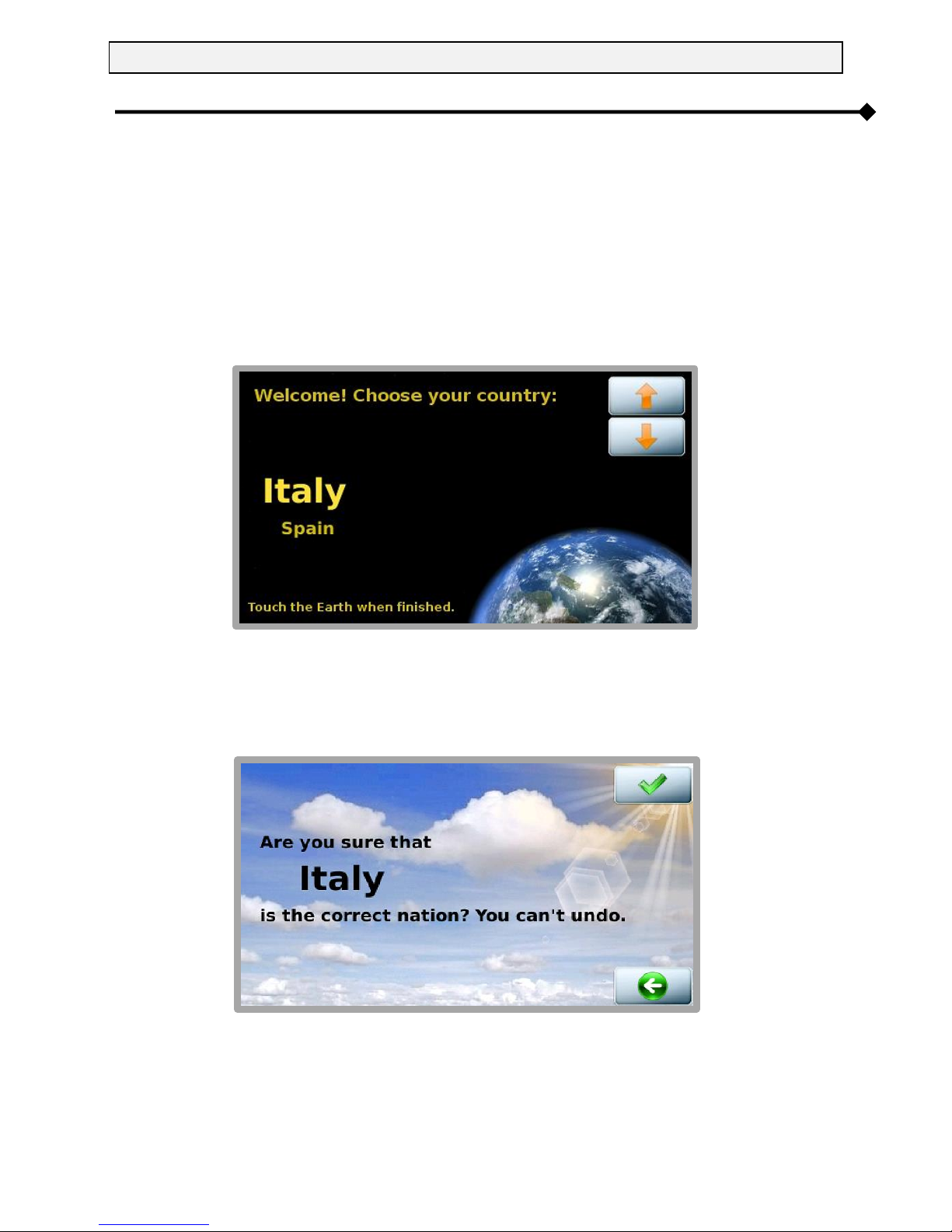
CAUTION: Choosing the country configures the inverter to the values prescribed by
the regulations in force in the country of installation. Once you have made your
choice, you cannot change this setting without contacting Technical Assistance
Service staff. The interface language can still be changed at a later date using the
ADVANCED SETTINGS menu.
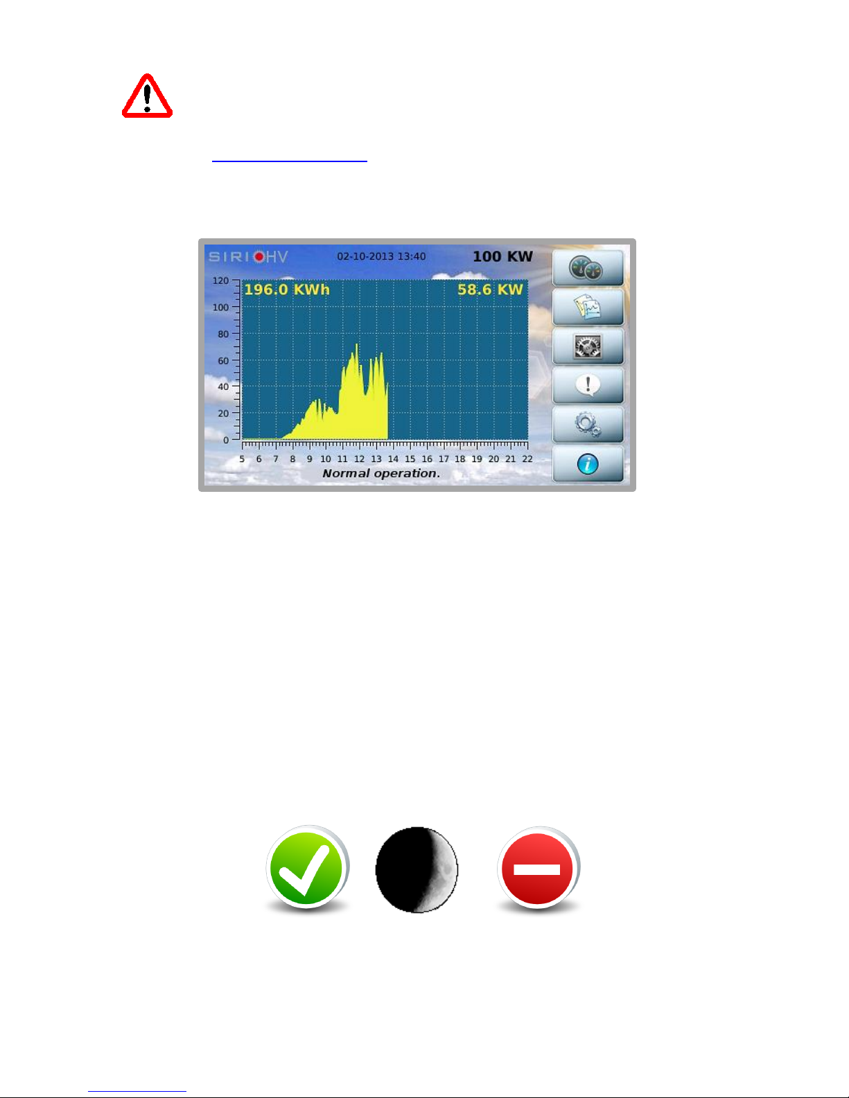
The next times the device is turned on, after the welcome AROS logo, the screen will appear as
shown below (the background color may vary according to the inverter operating conditions):
The screen consists of the following main areas:
1. At the top of the screen, the model, date, time and rated power of the inverter are displayed
from left to right.
2. The daily graph showing the power delivered is shown in the middle of the screen. The
horizontal scale represents the hours (from 5 to 22 i.e. 5 am to 10 pm) while the vertical scale
represents the kW. In the top right of the graph is the value of the instantaneous power while
on the left is the energy produced during the current day.
3. At the bottom of the screen is a line providing status information, with messages that alternate
once per second.
4. On the right of the screen, there is a column with buttons that allow you to navigate within the
interface.
After 5 minutes of inactivity, the LCD screen enters screensaver mode. Just tap it to return to normal
viewing. The following symbols may appear on the off screen during daytime:
The first symbol indicates that inverter operation is regular, the second that solar radiation is low and
the third indicates an alarm.

6
The buttons on the right-hand side of the column let the user access the main functions; they have the
following symbols and meanings:
Inverter measurements
Page 8
Data log
Page 11
System configuration
Page 15
Inverter statuses and alarms
Page 30
Inverter actions
Page 29
Information
Page 30
Note that, on the main screen, touching the graph area of the screen displays the energy produced
monthly:
Swiping the finger on the screen from left to right or from right to left it’s possible to see data of
previous/next month. Touching it again will display the annual graph:

7
Swiping the finger on the screen from left to right or from right to left it’s possible to see data of
previous/next year
Touching it again returns you to the home page.
Basic interactions
All the features and customizations of the system can be queried using the following actions:
Touch: touching the button or specific area of the screen;
Swipe: moving your finger on the screen while holding it down, from right to left or from left to
right. This may be required to navigate through the daily graphs or between different screens
on some occasions.
Whenever a touch or swipe is recognized, the MMI will confirm with a beep.
For file transfer, a USB flash drive with a single FAT32 partition is required;
otherwise it will be impossible to complete the data saving operation correctly.

8
Description of the Menu
MEASUREMENTS
From the main window, as seen, you can access the other areas of the interface. In particular, press
the button to consult the inverter measurements:
The synoptic panel shows all the main device measurements.
The two buttons on the right-hand side allow you to view the temperatures measured inside the
inverter and the measurements of the four analogue probes if connected.
By pressing the Temperature button accesses the following screen.
If a DC-BOX is present that monitors the current for each individual input
(and suitably configured), pressing the button allows for viewing the current readings for
each input.

9
In this window it is possible to change the ‘weight’ parameter for each input in relation to the
photovoltaic panels supplied, by pressing the relative ‘%’ key located beneath each reading.
For example: if inputs 1, 2, 3, 5, 6, 7 and 8 have a rated current of 180 A while input 4 has a rated
current of 140 A, the relevant settings are:
%1 = 100% - %2 = 100% - %3 = 100% - %5 = 100% - %6 = 100% - %7 = 100% - %8 = 100%;
%4 = 140/180*100 = 77.7 78%
See the next screen.
Press the ‘%’ key to access the following screen where the weight of the single string (in this example,
78) can be set through the + / –buttons.
NOTE:
in the event that not all of the 8 inputs are used, the free input reading must be deactivated. Press the
‘%’ key corresponding to the free input and set the ‘weight’ to zero.

10
By pressing the analogue probes accesses the following screen.
The button is used to return to previous windows, this button is available in all windows.

11
HISTORICAL DATA
The button allows you to access the screens for managing the historical inverter data:
1 view LOGS
2 save LOGS
3 delete LOGS
4 save SYS LOGS
5 save total LOGS
To view the logs, press the button with the symbol. Then select the measurements to be
displayed (only two measures can be displayed at the same time):
To select a measurement, press the corresponding button.
A white tick will appear on a green background to highlight the choice.
If you want to deselect an item, simply press the button again.
To proceed with reading of graphs, press button

12
Now you can :
Go ahead and back one day with a simple touch: scrolling across the screen from right to left
and from left to right respectively
With the lens button to enlarge the graph.
Send graphic via email (the button appears only if the service is configured).
Select the day you wish to view from the calendar
The units of measurement appear at the bottom. The horizontal axis is always temporal in the time
range [5 - 22]. The vertical axis on the left has the left-hand unit of measurement and the one on the
right has the right-hand unit of measurement. The curves always have different colours.
To save the historical data on a USB flash drive, press the button with the symbol. The
following window appears:
As already mentioned, the USB flash drive must be FAT32 (VFAT) formatted and have a single
partition. Many USB flash drives that have dedicated protection software with special partitioning
schemes may not work.

13
After inserting the USB flash drive, wait a few seconds and press the button with the symbol to
allow the system to recognize the memory (recognition is not automatic). If the operation succeeds,
the following message will appear:
Otherwise:
Press again to copy.
When finished, press the button with the symbol in order to safely remove the USB flash drive.
Note that over time, the historical data takes up the device memory.
The button allows you to manage the archives, eliminating annual data no longer of interest:
To select the year, drag your finger from right to left or from left to right.
When is pressed, the year will be highlighted in red. Touch the screen to confirm deletion.
Please note that data deletion cannot be reversed.

14
In order to download the system log from the control board (file history and ram, useful if required
by Technical Assistance in order to diagnose any problems), press the button with the symbol.
From the screen that follows
follow the instructions to start downloading the system card logs. To cancel the operation, go back to
the previous screen.
Or press to cancel the operation and return to the previous screen.
At the end of the download, you can send the logs by e-mail or copy to a USB flash drive.
The button allows the user to download the logs of the system board and of the display on
USB key. Use the same procedure seen before.

15
CONFIGURATION
From the main screen, press to access parameter configuration:
1 user
2 advanced
3 terminal
4 service
5 e-mail
On the right are the buttons that allow for setting the various parameters, namely:
- user settings
- advanced settings
- access to the terminal mode for low-level interactions with the inverter
- Service section, protected by password
- e-mail configuration section: this screen allows for setting the periodicity of the e-mails on an
alarm or event basis
USER SETTINGS
These are activated by pressing :
On this screen, you can manually set the €/kWh ratio and reset the partial hour meter for the energy
produced.

16
Press on the other hand to access screen brightness configuration and enable/disable the
buzzer. If enabled, the buzzer will sound an alarm that disappears when the alarm stops. The alarm
sound changes if an operator interacts with the interface.
After 20 minutes of inactivity, if an alarm is still active, the sound will go back to the initial one.
The button allows to set Date and Time on the inverter :
Press on the Month and Year to modify them.
WARNING: Modifying the Date and Time values during normal operation may alter
the graphic depiction of the memorised data.

17
Press to set the inverter identifier, needed in order to use the protocols on the 485 serial line
and to identify the machine when transferring historical inverter data onto a USB flash drive. If the
system has multiple inverters, it is compulsory for the identifiers to be all different from each other.
In the same window, we see that for each serial port, it is possible to specify whether the addressing
is dynamic or static
1
; this is a technical issue that regards the compatibility of communication
protocols. In particular, this configuration data concerns the PVSER protocol (Proprietary Protocol).
Also from here, by pressing you can specify the name of the system in which the inverter is
installed or the section of the system:
1
For more information, consult the SunVision 2 software user manual

18
Going back to user settings, using the button, you can configure the four analogue probes
(optional - e.g. radiation, temperature, anemometer etc, with electrical output 0-10 V):
By pressing one of four buttons, you configure the individual probe:
The single measurement, as seen, can be configured in detail:
Description
Unit of measurement
Minimum value (corresponding to 0 VDC input)
Maximum value (corresponding to 10 VDC input)
The probe can be enabled or disabled as desired.
Press the button with the symbol to save the probe configuration. Consult the technical
documentation for the 0-10 V probes to enter the correct configuration data.
Table of contents
Popular Touch Panel manuals by other brands

TIS
TIS TER-4G installation manual

Moxa Technologies
Moxa Technologies MPC-2240 Series Quick installation guide

Keba
Keba OP 460-LD/A Project engineering manual

Armacost Lighting
Armacost Lighting 733121 quick start guide

Unipulse
Unipulse DeviceNet F381A Operation manual

AMX
AMX MVP-9000i Operation and reference guide