ARQAMI HUMMER-D5 User manual

Downloaded from www.arqami.net manuals search engine
All-in-One POS System
User Manual
ARQAMI HUMMER
Ver. 1.2
© Copyright ARQAMI

Downloaded from www.arqami.net manuals search engine
General Information
ABOUT THIS MANUAL
The purpose of this user’s manual is to provide general information onTYSSO POS System
and to show the users how to configure the hardware-related configurations. The
information in this manual is subject to change without notice due to rapid improvement onIT
technology.
Users can get the most up to date information from our web sites:
U
http://www.arqami.net
DISCLAIMER
This manual has been examined for accuracy. While precaution has been taken in the
preparation of this manual, neither the manufacturer takes no liability for errors or omissions nor
assume anyresponsibility for damage(s) incurred directly or indirectly from errors, omissions, or
discrepancies ofthismanual.
IN NO EVENT WILL THE VENDOR BE LIABLE FOR DIRECT, INDIRECT, SPECIAL,
INCIDENTAL, OR CONSEQUENTIAL DAMAGES ARISING OUT OFTHE USE OR INABILITY
TO USE THIS PRODUCT OR DOCUMENTATION, EVEN IF THE POSSIBILITY OF SUCH
DAMAGES HAS BEEN ADVISED. IN PARTICULAR, THE VENDOR SHALL NOT HAVE
LIABILITY FOR ANY HARDWARE, SOFTWARE, OR DATASTORED OR USED WITH THE
PRODUCT, INCLUDING THE COSTS OF REPAIRING, REPLACING, ORRECOVERING SUCH
HARDWARE,SOFTWAREORDATA.
WARNING
The terminal has been tested and found to comply with the limits for a Class a digital device,
pursuant to Part 15 of the FCC rules. These limits are designed to provide reasonable protection
against harmful interface in a residential installation. This equipment can generate and radiate
radio frequency energy and, if not installed and used according to the instructions, may cause
harmful interference toradio communications. However, there is no guarantee that interface will
not occur under particular installation. If this equipment does cause harmful interference toradio
or television reception, which is found by turning the equipment off and on, the user is
encouraged totry to correct the interface by one or more of the following measures:
Reorient or relocate thereceiving antenna
Increase the distance between the equipment or device
Connect the equipment to an outlet other than the receiver’s
Consult adealer or an experienced radio/TV technician for assistance
i

Downloaded from www.arqami.net manuals search engine
CAUTION
The system is provided with a battery-powered Real-Time Clock circuit. There is a danger of
exposing and personal injury ifthe battery isincorrectly replaced ormistreated. Donot attempt to
disassemble the battery, immerse it in the water or expose it to fire.
WARRANTY LIMITS
If the product and the parts are disassembled by any person other than the authorized
technicians, the warranty will be terminated. The users should consult his/her dealer for any
technical problems. Warranty does not cover anydamage caused by improper use.
TRADE MARKS AND SERVICE MARKS
TYSSO is a registered trademark of FAMETECH INC.
Other brand andproduct names are trademarks and registered trademarks and service marks of
theirrespectiveowners.
ii

Downloaded from www.arqami.net manuals search engine
IMPORTANT SAFETY INFORMATION
Readfollowing instructionscarefully.
Useonly parts, especially power adapter,recommended bythe manufacturer; unapproved
parts may behazardous.
Before plugging the power cord into theAC inlet of the power supply unit, make sure that
the voltage applied to the power outlet is within the specified range (100V ~240V).
Improper power source voltage range will cause damage tothe power supply unit.
Power offthe system and remove the power adapter while cleaning the system.
Before powering on the system, make sure all the peripherals are firmly installed.
Do not use the system near water, such as a bathtub, a washbowl, akitchen sink, a laundry
tub, and a swimming pool. Do not expose the machine under direct sunlight, and keep it
away from any heat source.
Do not place the system on an unstable cart, stand or table. If the machine falls, it may injure
aperson or cause serious damage tothe appliance.
The system is equipped with a three-wire grounded plug with a third (grounding) pin. This is a
safety feature. If your outlet does not accommodate the three-wire plug, have an electrician
install a correct outlet, or use an adapter to ground the appliance safely. Do not leave out the
safety purpose of the grounded plug.
Do not allow anything to rest on the power cord. Do not locate the system where people may
walk on thecord.
Donot make the power outlet and extension cords overload. Overload can result in fire or
electricshock.
Donot push any object into the computer cabinet. Dangerous voltage points may betouched
and the parts may beshorted out resulting in fire or electric shock.
Donot attempt to service the system on your own. Opening or removing cover can expose
you to dangerous voltage or other hazards.
Power offthe system before installing or removing non-PNP (plug and play) devices.
If any of the following situations occurs, unplug the systems from the power outlet
immediately and consult with a qualified service person:
1. The power cord or plug is damaged or frayed.
2. Liquid is spilled into the system.
3. The system is dropped or the cabinet is damaged.
When the system is not in use, cover the system and store it with care.
iii

Downloaded from www.arqami.net manuals search engine
Contents
General Information....................................................................................................i
ABOUT THIS MANUAL..........................................................................................................i
DISCLAIMER .........................................................................................................................i
WARNING..............................................................................................................................i
CAUTION .............................................................................................................................. ii
WARRANTY LIMITS............................................................................................................. ii
TRADE MARKS AND SERVICE MARKS............................................................................. ii
IMPORTANT SAFETY INFORMATION ................................................................................iii
1.
Product Overview.................................................................................................1
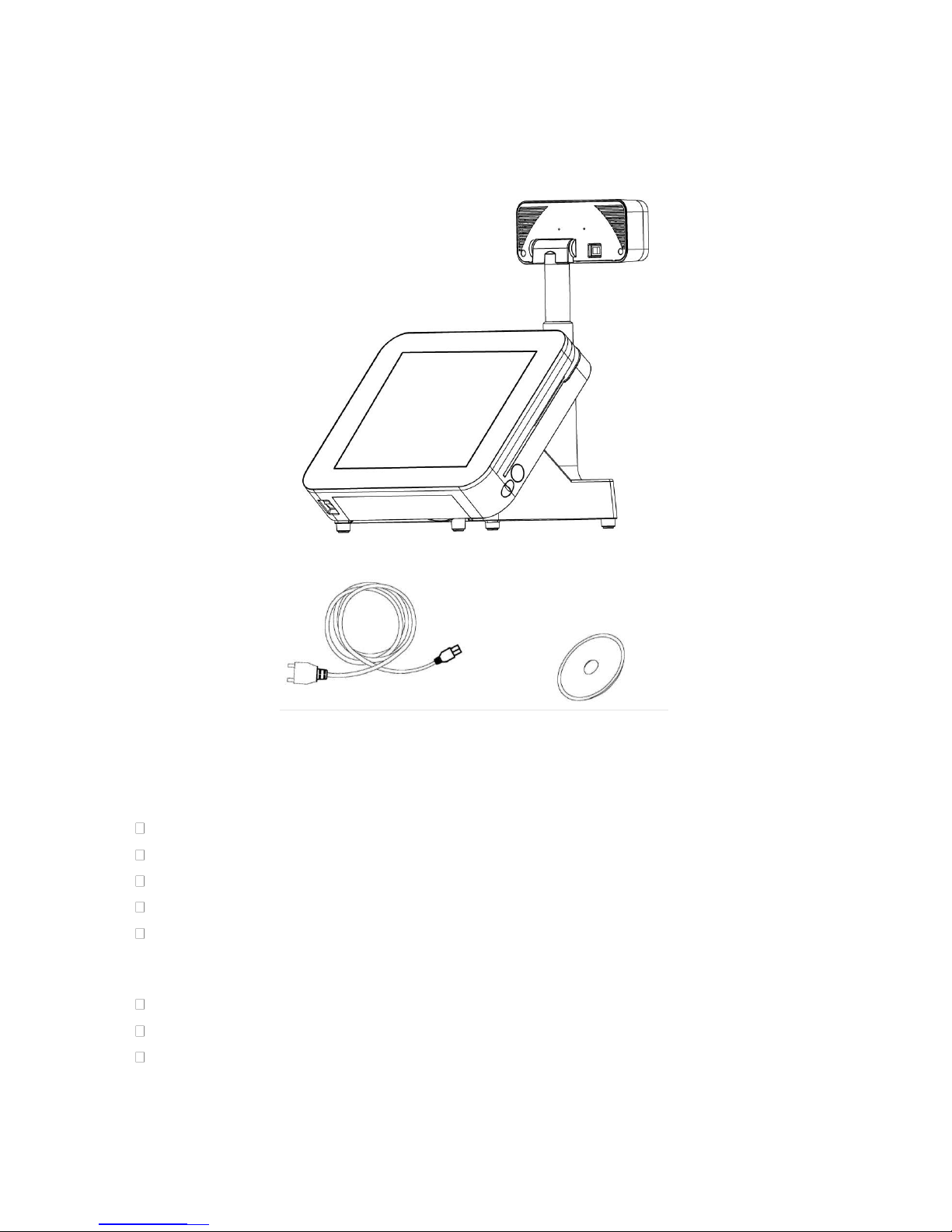
1.1. Items ............................................................................................................................1
1.2. Specifications...............................................................................................................2
1.3. Parts Description..........................................................................................................6
1.4. I/O Ports.......................................................................................................................8
2.
Components & Peripherals Installation ...........................................................10
2.1. Unpack Your POS ......................................................................................................10
2.2. Install Your POS System............................................................................................11
2.3. Replace the Hard Disk ...............................................................................................12
2.4. Plug AC Power Cord to thePOS System......................................................................13
2.5. I/O Interface ...............................................................................................................14
2.6. Install Your Receipt Printer (Optional)........................................................................15
2.6.1.
Install/Replace the Paper Roll........................................................................................15
2.6.2.
Buttons & Indicators of Receipt Printer Unit..................................................................16
2.6.3.
Dip Switch Configuration of the Receipt Printer............................................................17
2.6.4.
Virtual Serial Port Installation (for USB Connection Only)............................................19
2.6.5.
Install the Driver and Setup of Receipt Printer Unit.......................................................24
2.7. Adjust the Customer Display (Optional).....................................................................30
2.8. Configuration of Customer Display............................................................................30
3.
BIOS Setup .........................................................................................................31
3.1. Main Menu.......................................................................................................................32
3.2. Standard CMOS Features..........................................................................................33
3.3. Advanced BIOS Features..........................................................................................34
3.4. Advanced Chipset Features ......................................................................................36
3.5. Integrated Peripherals................................................................................................38
3.5.1.
OnChip IDE Device.........................................................................................................39
3.5.2.
Onboard Device ..............................................................................................................41
3.5.3.
Super IO Device..............................................................................................................42
3.5.4.
Second IO Device...........................................................................................................43
3.5.5.
USB Device Setting.........................................................................................................44

Downloaded from www.arqami.net manuals search engine
3.6. Power Management Setup ........................................................................................45
3.7. PnP/PCI Configurations.............................................................................................47
3.8. PC Health Status.................................................................................................................48
3.9. Frequency/Voltage Control........................................................................................49
3.10. Load Fail-Safe Defaults .............................................................................................50
3.11. Load Optimized Defaults............................................................................................51
3.12. Set Supervisor Password...........................................................................................52
3.13. Set User Password ....................................................................................................53
3.14. Save & Exit Setup......................................................................................................54
3.15. Exit Without Saving....................................................................................................55
4.
Install the Drivers of POS Terminal......................................................................56
4.1. Install the Chipset Driver............................................................................................57
4.2. Install the Graphics Driver..........................................................................................59
4.3. Install the Audio Driver...............................................................................................63
4.4. Install the LAN Driver .................................................................................................65
5.
Install the Touch Screen Driver.........................................................................67
5.1. Install the Driver of Resistive TypeTouch Panel........................................................68
5.2. Touch Screen Calibration (Resistive Type)......................................................................72
6.
Peripherals Testing................................................................................................... 75
6.1. Install the Wi-Fi Driver (Optional)...............................................................................76
6.2. Test Your Magnetic Stripe Card Reader(MSR) and i-Button Module.........................80
6.3. Test Your Customer Display.......................................................................................86
6.4. Cash Drawer ..............................................................................................................88
7.
Jumper Settings & Connectors.........................................................................91
7.1. The Main Board Jumper Location..............................................................................91
7.2. Jumper Settings.........................................................................................................92
7.3. Connector Function List.............................................................................................95
7.4. Internal Connector Pin Assignment ...........................................................................96

Downloaded from www.arqami.net manuals search engine
v

Downloaded from www.arqami.net manuals search engine
1. Product Overview
1.1. Items
POS System
MainSystem
AC Power Cord Driver/UtilityCD
HDD (2.5” SATA)/ Compact Flash (Optional) / Disk on Module (Optional)
SODIMM DDR3 (1 ~ 4GB)
CPU: IntelAtom D525 Dual Core(1.8GHz , 1MB Cache)
Power Adapter (Hidden under Base)
AC PowerCord
Driver/UtilityCD
Optional Accessories
Magnetic StripeCard Reader (MSR)
CustomerDisplay
Wi-Fimodule
Thermal ReceiptUnit
I-Button
SecondaryDisplay
*
For more information relating tothe other optional peripherals, please contact the local representatives or
technical support personnel of the providers.
1

Downloaded from www.arqami.net manuals search engine
1.2. Specifications
Model
-D5
Main Board
CPU
Intel Atom D525 Dual Core (1.8GHz, 1MB Cache)
Chipset
Intel D525 + ICH8M
System Memory
2 x 204pin DDR3 SODIMM Socket , up to 4GB
Graphic Memory
Share System Memory 64~224MB
OS Support
Linux, POS Ready 2009, POS Ready 7,
Windows XP Pro, Vista, Windows 7
Display
Display Type
15" LCD Monitor
Brightness
250 nits
Resolution
1024 x 768 Pixel
Touch Screen
Flat 5 Wire Resistive Type
Tilting Angle
Fixed 50 Degree
Storage
HDD
1x 2.5" SATA
Compact Flash
1 x Slot Type I II
Interface
Serial
2 x COM with Power Selected 5/12V
1 x COM without Power Output
Parallel
1 x DB25 Parallel Port
USB
6 x USB 2.0 (External)
2 x USB 2.0 (Internal, 1 reserved for touch screen)
Mini-PCIe
1 x Internal
PS/2 Mouse
1 x 6-pin Mini DIN
PS/2 Key Board
1 x 6-pin Mini DIN
LAN
1 x RJ-45, Giga LAN Support
VGA
1 x DB-15, Female
DC Out
1 x 12VDC Jack for Customer Display or 2nd Display
Cash Drawer
1 x RJ-11, 12/24 VDC Selectable
Audio Jack
1 x Line Out, 1 x MIC In, 2 x Internal Speaker 2W
Others
Power Input (Main Unit)
12VDC 90W,4-pin Connector with Lock
(External Adaptor: 100~240 VAC, 50/60HZ)
Power Input (Printer Unit)
24VDC/2.5A
(External Adapter 100~240VAC 50/60Hz)
Color
White, Black, Orange
Compliance
FCC / CE / WEEE / RoHS
Weight
8.5 Kg
Dimension (W x D x H:mm)
370 x 320 x 300
Operating Temperature
0°C~40°C
Operating Humidity
20% ~ 80% RH non-condensing
Storage Temperature
-20°C~ 60°C
Storage Humidity
20% ~ 85% RH non-condensing
2

Downloaded from www.arqami.net manuals search engine
Printer Unit (Optional)
General
Print Method
Thermal line printing
Print Speed
250mm/sec
Print Life
100 Km
Print Font
ANK Font
Font A: 12 x 24 dots
Font B: 9 x 17 dots
Chinese character: 24 x 24 dots
Print Resolution
576 dots/line or 512 dots/line
Print Font Character Support
International Font, Big 5 Chinese, GB Chinese,
Japanese, Korean selectable
Character Per Line
48 (Font A) / 64(Font B)
Effective Print Width
72mm
Paper Width
79.5mm± 0.5mm
Paper Roll Diameter
83mm
Paper Thickness
0.06~0.08mm
Print Command
ESC/POS commands set compatible
Auto Cutter
Partial
Paper End Detection
Yes
Over-Heat Halt-on Protection
Yes
Interface (Printer)
Serial
Multi I/O Interface
(Serial +Ethernet +USB)
USB
Ethernet
Cash Drawer
DC 24V/1A, 6-Wire RJ-11 Socket
Others
Power Input (Printer)
24VDC/2.5A
(with External Adapter 100~240VAC 50/60Hz)
Operating Temperature
0°C~45°C
Operating Humidity
10% ~ 80% RH non-condensing
Storage Temperature
-10°C~ 60°C
Storage Humidity
10% ~ 90% RH non-condensing
3

Downloaded from www.arqami.net manuals search engine
Customer Display Unit (Optional)
General
Display Type
Vacuum Fluorescent Display
Brightness
700 cd/m2
Number of Columns
20 x 2
Character Size (mm)
6.4 x 9.2 (W x H), 5x7 dot matrix
Command Set
ESC/POS
Font Character Support
96 Alphanumeric & 13 international
Interface
RS-232.
Others
Power Input
DC +9V~12V(RS-232)
Power Consumption
4.5 W (RS-232)
Material
ABS
Compliance
CE, FCC
Display Unit
218 x 87 x 45 mm
Support Pole
Telescopic Pole (280~459 mm adjustable)
Base
140 x 18 x 86 mm
Horizontal Rotation
±180 degree
Tilting Angle
53 degree, 4 step adjustable
Operating Temperature
0°C~40°C
Storage Temperature
-10°C~ 50°C
Relative Humidity
0% - 90% RH, non-condensing
Optional Peripherals
MSR
3 Track, PS/2 or USB or COM
i-Button
Dallas Key RS232 I/F
2nd Display
8.4”, 10.4”, 12.1”, 15” with or without Touch
Wi-Fi
Mini-PCIe interface Module
*
For more information relating tothe other optional peripherals, please contact the local representatives or
technical support personnel of the providers.
4

Downloaded from www.arqami.net manuals search engine
Dimensions
Left View Front View
Right View
(VFD Pole max. height)
Right View
(VFD Pole min. height)
5

Downloaded from www.arqami.net manuals search engine
1.3. Parts Description
FrontView
Touch Screen
Power Switch of
Customer Display
Power Switch
Bottom I/O Cover
RearView
Customer Display
Receipt Slot
HDD Cover
Printer Cover
Button
Paper Feed
Button
Printer Cover
Power Switch of
Receipt Printer Unit
6

Downloaded from www.arqami.net manuals search engine
BottomView
Bottom I/O Cover
I/O Ports for
Printer Unit
AC Power Cord
Connector
Side View
Left View Right View
7
MSR
i-Button

Downloaded from www.arqami.net manuals search engine
1.4. I/O Ports
Side I/O ports
Bottom I/O ports
Bottom I/O Cover
Printer I/O ports
Bottom I/OPorts
Side I/O Ports
I/O Ports for Printer Unit
* Printer Unit is an optional part and may not include in the product.
8
USB
RJ-11
PWR

Downloaded from www.arqami.net manuals search engine
I/O Port
Description
USB
Connect devices with USB connectors. There are 6 external USB ports available,
(4 locate on the bottom and 2 left side ports).
Mouse
PS/2 mouse connector
KB
PS/2 keyboard connector
PWR IN
A 4 din rounded-power-jack for connecting an AC to DC +12V power adapter.
PWR COM
COM 1/2 support power RI/5/12V,
refer to PWR COM Jumper Setting (as shown in the image below).
Extend KB
8-pin pitch 2.0 for keyboard.
AUDIO OUT
Earphone or speaker connector with 2 internal speakers.
MIC IN
Microphone connector
DC12V OUT
12VDC jack for customer display or 2
nd
VGA monitor.
Serial Ports
There are 6 x COM ports available.
3 x External COM :
2 x COM with 5/12VDC Power Selectable on pin-9 by jumper,
1 x COM does not supply power.
3 x Internal COM:
1 x COM for Touch Option, 1x COM for MSR, 1 x COM Reserved.
CASH DRAWER
1 x RJ11 connector with selected 12/24V,
* Please refer to PWR COM Jumper Setting (as shown in the image below).
LAN
1 x RJ-45 connector with link/act integrates speed LED and supports
wake-from-LAN function.
CF
1 x CF card.
VGA
1 x 15 pin D-type connector serves to transmit VGA data to the monitor.
PWR COM and Cash Drawer Voltage Jumper Settings
Setting
+12V
+5V
Modem Ring In
(Default)
COM 1
1-2
3-4
5-6
COM 2
7-8
9-10
11-12
Setting
+12V
+24V
Cash Drawer
13-14
15-16
9

Downloaded from www.arqami.net manuals search engine
2. Components & Peripherals Installation
2.1. Unpack Your POS
Thecontents may vary with different options. Ifthere’s any physical damage ormissing parts,
please contact your supplier immediately. Please keep all packing materials in case you
need to ship back the device for service.
Unpacking
The product and accessories are packed in a paperboard carton. And it is wrapped by foam
padding for protection during shipping.
10

Downloaded from www.arqami.net manuals search engine
2.2. Install Your POS System
The product is a fully integrated POS System and easy for installation.
Toinstall the POS System:
1. Place the product on the location.
2. Plug theAC power cord to the POS system
3. Connect the optional peripherals tothe POS (for example: Mouse, Keyboard, and
Barcode Scanner.)
4. Plug theAC power cord to the power source (for example: electrical outlet).
5. Turn on the switch of the Printer Unit and Customer Display (if pre-installed) and the
otheroptionalperipherals.
6. Turn on the POSSystem.
Note:
Always install the POS system and the optional peripherals on aflat, clean and stable
location surface with additional cushioned material (for example: blanket).
Toprevent obstruction on the operator, reserve appropriate space for the POS system
and remove unnecessarily objects oritems.
11

Downloaded from www.arqami.net manuals search engine
2.3. Replace the Hard Disk
HDD Cover
a. Loosen the securing screw toremove
the HDDcover
Note:
Toprevent injuries to the LCD Panel,
Carefully lay the front of the unit face down
on a flat, clean and stable surface with
additionalcushionedmaterial
(for example: blanket).
HDD Slot
With
HDD Module
b. Pull the HDD Module to the left to
detach it from the POS unit.
Disconnect the HDD Cable to remove
the HDDModule.
Remove the HDD Module
HDD Bracket
Protective Film
c. Loosen the securing screws to
remove the hard disk from the
bracket.
Then replace a new hard disk (with
protective film attached to the HDD)
d. Re-install the HDD module and
replace the HDD cover to the POS.
12

Downloaded from www.arqami.net manuals search engine
2.4. Plug AC Power Cord to the POS System
a. Thepower adapter should be found
on the bottom of thebase.
Carefully lift up the POS and there is
a power connector in the bottom (as
imagebelowillustrated).
Note:
Toprevent injuries to the LCD Panel,
Carefully lay the front of the unit face down
on a flat, clean and stable surface with
additional cushioned material (for
example: blanket).
b. Plug theAC power cord into the
powerconnector.
c. Plug theAC power cord in to the
ACoutlet.
13
Table of contents