5
Trouble Shooting Matrix (cont.)
Maintenance Schedule
Problem Possible Cause Solution
SLUGGISH PERFORMANCE
(continued)
Slipper clutch adjustment too loose Check slipper is set to factory setting or your
prefered setting - see page 7 or model manual
Initial acceleration mode or reverse speed
on MEGA waterproof ESC set too low
Modify MEGA waterproof ESC settings
MEGA electric motor dirty or damaged Clean, check condition and/or replace - visit
ARRMA-RC.com for more information
Drivetrain dirty or damaged Clean, check condition and/or replace - visit
ARRMA-RC.com for more information
FRONT WHEELS LIFT WHEN
ACCELERATING
Slipper clutch adjustment too tight Check slipper is set to factory setting - see
page 7 or model manual
NO CONTROL OF VEHICLE
OR SHORT RANGE
ARRMA ATX transmitter batteries are
weak or fitted incorrectly
Check transmitter batteries and refit - see
model/transmitter manual
Servo and ESC signal wires to ARX
receiver loose or connected incorrectly
Reinstall signal wires to receiver
ARRMA transmitter and receiver are not
'bound' correctly
Transmitter and receiver need to be bound -
see model/transmitter manual
STEERING/THROTTLE
OPERATION INTERMITTENT
ESC has shut down due to overheating Stop driving and allow ESC or motor to cool
down
ARRMA transmitter and receiver are not
bound fully or are suffering interference
Check for sources of interference and re-bind
transmitter/receiver - see transmitter manual
VEHICLE WANDERS LEFT/
RIGHT WITHOUT STEERING
INPUT
ARRMA ATX Steering trim setting out Adjust steering trim - see model/transmitter
manual
Damaged steering components C h e c k co m p o n e n t s a n d r e p l a c e - v i s i t
ARRMA-RC.com for advice
Drivetrain dirty or damaged Clean, check condition and/or replace - visit
ARRMA-RC.com for more information
STEERING OR THROTTLE
FUNCTION REVERSED
Relevant channel of ARRMA ATX
transmitter is reversed
Reverse relevant channel on ARRMA ATX
transmitter - see model/transmitter manual
Check that the wires from the ESC to the
motor are connected correctly
Reconnect in the correct orientation (orange
to red and blue to black) ensuring fit is tight; if
not pinch female connector with pliers
LIMITED STEERING ANGLE ARRMA ATX transmitter steering dual-
rate set incorrectly
Adjust ARRMA ATX transmitter dual-rate -
see transmitter manual
Damaged steering components C h e c k co m p o n e n t s a n d r e p l a c e - v i s i t
ARRMA-RC.com for advice
MEGA waterproof ESC is damaged Replace with new unit - visit ARRMA-RC.com
for advice and upgrades!
Maintenance
This chart is just a guide. Running in dusty, sandy or wet conditions will mean
certain maintenance tasks will need to be performed more frequently. Check for wear or damage after every run. Do not
wait until the recommended time for maintenance if parts appear badly worn or need renewing.
Maintenance Task Page Runs
Chassis Maintenance 6
Wheel and Tyre Maintenance 6
Slipper clutch Adjustment 7
Spur/Pinion Mesh Adjustment 7
Slipper Pad Replacement 8
Driveshaft Maintenance 9
Rear Axle Maintenance 9
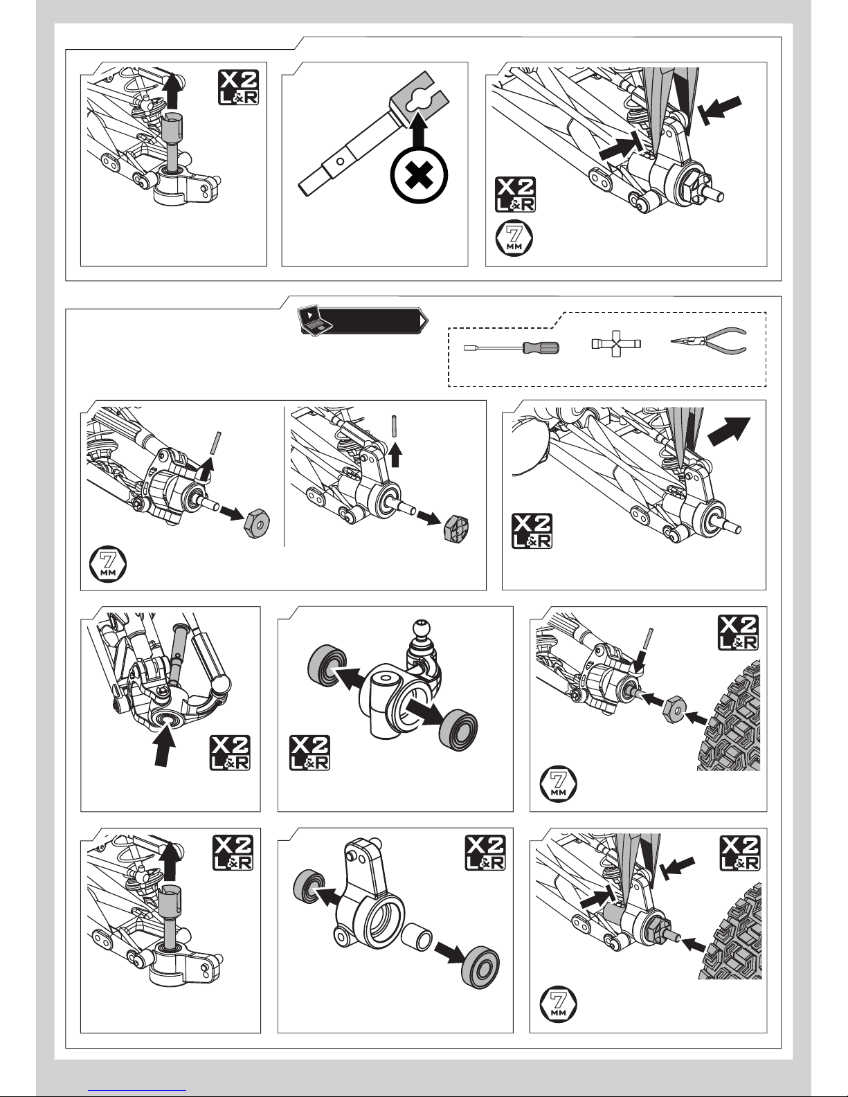
Wheel Bearing Replacement 10
Shock Oil Replacement 14
Differential Oil Replacement 16