Arrow LW82 Instructions for use

www.arrowsheds.com
Customer Service:
1-800-851-1085 or
BUILDING DIMENSIONS
8’ x 2’
Nominal Size
Gloves must be worn
at all times to reduce
risk of injury!
Size rounded off to the nearest foot
* See Inside for Detailed Safety Information.
Owner’s Manual
& Assembly Guide
01HG
729240519
†
Base
Size
For proper base construction see page 8
Exterior Dimensions
(Roof Edge to Roof Edge)
Width Depth Height
Interior Dimensions
(Wall to Wall)
Width Depth Height
Door
Opening
Width Height
Approx.
Size
Storage
Area
8’ x 2’ 17 Sq. Ft. 100 Cu. Ft. 99 3/4” 30 3/4” 82 1/8” 94 3/4” 25 1/2” 80 1/8” 43 1/2” 60”
2,4 m x 0,6 m 1,6 m22,8 m3253,4 cm 78,1 cm 208,6 cm 240,7 cm 64,8 cm 203,5 cm 110,5 cm 152,4 cm
†
Model No.
LW82
97 1/2” x 28 1/4”
247,7 cm x 71,8 cm


3
• Keep children and pets away from the worksite during construction and until the building is completely assembled. This will
help avoid distractions and any accidents which may occur.
03HN
• Care must be taken when handling various pieces of your building since many contain sharp edges.
CAUTION
• Do NOT attempt to assemble your building before double checking that you have all the parts indicated in the parts lists.
Any building left partially assembled may be seriously damaged by even light winds.
• Do NOT attempt to assemble your building on a windy day. The large panels can catch the wind like a “sail”, making
construction diffi cult and unsafe.
Your building MUST be anchored to prevent wind damage.
• NEVER concentrate your weight on the roof of the building.
Watch the Weather Closely
• Before assembling any parts, your base should be constructed and an anchoring system should be ready to use.
ASSEMBLY
• The best location is a level area with good drainage.
• Allow enough space outside the building to be able to access the roof with a ladder.
• Use Teamwork: Two or more people are required to assemble your building.
CARE & MAINTENANCE
• DO NOT use power washing to clean your shed.
• Combustibles and corrosives must be stored in air tight containers designed for chemical and/or combustible storage.
Corrosive chemicals such as fertilizers, pesticides and herbicides should be cleaned off the interior and exterior surfaces
immediately. Rust caused by chemical damage is not covered by the warranty.
RUST PROTECTION PRECAUTIONS
• Avoid nicking or scraping the coating surface, inside and out.
• Keep roof, base perimeter and door free of debris.
• Touch up scrapes or nicks and any area of visible rust as soon as possible.
For missing or damaged parts contact Customer Service. Do not return to store.

4
8
HARDWARE LIST...
Key Part Part Qty.
No. No. Description List
56
10
11
12
34
9
13 14
7
12
Hardware Views by Key No.
11/32 Hex.
#2 Phillips #2 Phillips
04HG
1 65103 Hex Nut (#8-32) 64
2 65900A Black Screw (#10B x 1/2) (13 mm) 8
3 65923 Bolt (#8-32 x 3/8) (10 mm) 64
4 65004 Screw (#8AB x 5/16) (8 mm) 200
5 66045 Door Handle 2
6 66646 Washer Sheet 4
7 65109 Acorn Nut 6
8 67468 Peak Cap 2
9 66769 Door Slide 4
10 66382 Lower Door Guide 4
11 66183L Left Roof Trim Cap 2
12 66183R Right Roof Trim Cap 2
13 67293B Weather Stripping 1
14 66775 Plug 2
#2 Phillips
5/16 Hex.
The fasteners used in each step are shown actual size at the top
of each page. If you are unsure which fastener to use, hold it up
to the picture and use the one that matches.

6
Key
No. Part No. Part
Description Qty.
PARTS LIST
5
05HG
Part Views
15 6243 Wall Panel 4
16 11297 Front Wall Panel 2
17 11294 Rear Wall Angle 2
18 8700 Right Gable 2
19 8701 Left Gable 2
20 10498 Horizontal Door Brace 4
21 6278 Vertical Door Brace 2
22 11295 1
23 11296 Door Track 2
24 10828 Roof Panel 2
25 10478 2
26 9369 Door Jamb 2
27 9924 Rear Wall Channel 2
28 6014 Side Roof Trim 2
29 6868 Ridge Cap 1
Door Track Splice
Door

6
Key
No. Part No. Part
Description Qty.
PARTS LIST
6
06HG
Part Views
30 10829 Roof Beam 4
31 9916 Side Wall Channel 2
32 6646 Side Wall Angle 2
33 8941 Ramp 1
34 9379 Front Floor Frame 2
35 9377 Rear Floor Frame 2
36 8984 Side Floor Frame 2
37 6668 2
38 7905 Roof Beam Bracket 4
39 9204 Roof Beam Brace 2
Corner Panel

7
07HG
22
25
27
23
20
24
18
26
16
17
21
18
17
19
15
15
16
24
28
29
25 26
34
35
27
30
31
32
23
28
30
30
31
33
34
35
36
36
30
ASSEMBLY BY KEY NO.
15 15
19
20
20
20
21
32
37
37
38 38
38
38
39
39

12
No matter which of the options below you choose for a base, an ARROW ANCHORING KIT is
recommended as an effective method of properly securing your building after assembly is complete.
OPTION 1: Directly on ground (earth)
Assemble your building directly on level ground (grass, dirt, rock, sand, etc.).
OPTION 2: Wood Platform
If you decide to build your own base, be sure to select the appropriate materials.
These are the recommended materials for your base:
• 2 x 4's (38 mm x 89 mm) Pressure Treated Lumber • 5/8" (15,5 mm) 4 x 8 (1220 mm x 2440 mm) Plywood-exterior grade
• 10 & 4 penny Galvanized Nails • Concrete Blocks (optional)
NOTE: Pressure Treated Lumber must not be used where it will make contact with your storage building. The properties of
Pressure Treated Lumber will cause accelerated corrosion.
The platform should be level and fl at (free of bumps, ridges etc.)
to provide good support for the building. The necessary materials
may be obtained from your local lumber yard.
To construct the base follow instructions and diagram.
Construct frame (using 10 penny galvanized nails)
Measure 16"/24" (40,6 cm/61,0 cm) sections to construct
inside frame (see diagram)
Secure plywood to frame (using 4 penny galvanized nails)
OPTION 3: Concrete Slab
The slab should be at least 4" (10,2 cm) thick. It must be level
and fl at to provide good support for the frame.
The following are the recommended materials for your base.
• 1 x 4's (19 mm x 89 mm) (will be removed once the concrete cures)
• Concrete • Sheet of 6 mil plastic
• We recommend for a proper strength concrete to use a mix of:
1 part cement • 3 parts pea sized gravel • 2 1/2 parts clean sand
Prepare the Site/Construct a Base
1. Dig a square, 6" (15,2 cm) deep into the ground (remove grass).
2. Fill up to 4" (10,2 cm) in the square with gravel and tamp fi rm.
3. Cover gravel with a sheet of 6 mil plastic.
4. Construct a wood frame using four planks of 1x4 (19 mm x 89 mm)
lumber.
5. Pour in concrete to fi ll in the hole and the frame giving a
total of 4" (10,2 cm) thick concrete. Be sure surface is level.
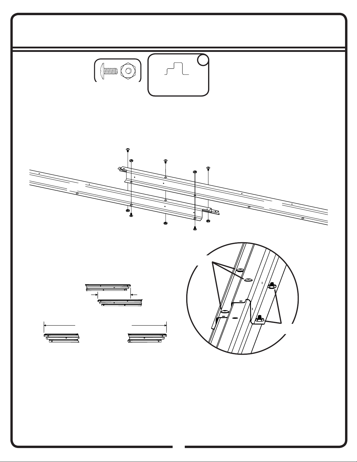
CONSTRUCTING A BASE...
FRONT
(DOOR)
FRONT
(DOOR)
Note: Finished Slab dimensions, with lumber removed.
Note: Platform/Slab will extend 9/16" (1,4 cm) beyond
fl oor frame on all four sides. Seal this 9/16" (1,4 cm)
of wood with a roofi ng cement (not included), or bevel
this 9/16" (1,4 cm) of concrete when pouring, for good
water drainage.
97 1/2"
247,7 cm
16"/24"
40,6 cm/61,0 cm
28 1/4"
71,8 cm
97 1/2"
247,7 cm
28 1/4"
71,8 cm
14GQ
8

9
95 7/8” 243,5 cm
9377
Rear Floor Frame
2
11 7/8” 30,2 cm
09HG
Step 1
You will need for this page:
(QTY: 5)
Bolts thru Bottom.
Bolts thru Top.
Overlap Length
Finished Length
9377
9377

10
9379
8941
9379
95 7/8” 243,5 cm
CHECK THAT ALL ASSEMBLED PARTS ARE THE CORRECT LENGTH BEFORE CONTINUING
FRONT
FRONT
Drain holes must face outside the building.
8941
Ramp
1
9379
Front Floor Frame
2
7 3/8” 18,7 cm
10HG
Step 1
You will need for this page:
(QTY: 8)
Overlap Length
Finished Length

11
Assemblies from Step 1:
• Front Floor Assembly (1)
• Rear Floor Assembly (1)
Do NOT fasten your Floor Frames to your Base at this time. You will anchor your building af-
ter it is erected. If using a Floor Frame Kit, you must wait until after assembly to install it.
The Floor Frame must be BOTH square AND
level or the holes will not line up properly.
Insert a bolt and nut thru bottom of
Front Floor Frame at each front corner
to secure Front Frame to Side Frames.
FRONT
When diagonal measurements
are equal, the Frame is square.
11HG
Step 1
(QTY: 8) (QTY: 2)
You will need for this page: 8984
Side Floor Frame
2
8984
8984
8984
9377
8984
9379

12
9924
Finished Length
94 5/8” 240,3 cm
(QTY: 2)
You will need for this page:
Step 2
6 1/8” 15,6 cm
Overlap Length
12HG
9924 2
Rear Wall Channel
11294 2
Rear Wall Angle
9924
11294
11294

13
Track Splice
1
11295
Door Slide
4
Door Track
2
11296
13HG
94 5/8” 240,3 cm
To remove or install Door Slides:
Remove Doors from Slides and set aside.
Using pliers, bend down a corner of the Door Track.
Remove or install Door Slides.
Carefully bend the corner back into position.
Slides should be installed in Door Track prior to installation. However, if this step is overlooked
or if the Slides need to be removed for maintenance, the following procedure may be used.
Painted Part
11296
CORRECT INCORRECT
Long Leg on top
Door Slide
END VIEW
Step 2
The bottom side of the Door Tracks and the Door
Track Splice has only four (4) holes. The top side
has many holes. Fasten bottom side only.
You will need for this page: 66769
11295
Finished Length
(QTY: 4)
11296

12
14HG
FRONT
14
Step 3
Floor Frame Assembly
11297
6243
6668
TOP VIEW
PANEL LAYOUT
6243
6668
11297
6243 6243

12
You will need for this page:
15HG
6243
Wall Panel
1
15
Step 3
Floor Frame Assembly
6243
(QTY: 9)
6668
Corner Panel
1
6668
Rear
1
Floor Frame
Assembly
Step 1
(QTY: 1)

12
You will need for this page:
16HG
16
Step 3
11297
(QTY: 4)
11297
Front Wall Panel
1
(QTY: 1)
FRONT
11297

12
You will need for this page:
17HG
6243
Wall Panel
1
17
Step 3
6243
(QTY: 9)
6668
Corner Panel
1
6668
Rear
(QTY: 1)

12
You will need for this page:
18HG
18
Step 3
11297
(QTY: 4)
11297
Front Wall Panel
1
(QTY: 1)
FRONT
11297

12
You will need for this page:
19HG
19
Step 3
6646
(QTY: 14)
6646
Side Wall Angle
2
6646
1
Rear Wall Angle
Assembly
Step 2
Rear Wall Angle
Assembly
Wall Angles must face
inside the building.
Rear
FRONT
Rear

12
You will need for this page:
20HG
20
Step 3
(QTY: 4)
1
Door Track
Assembly
Step 2
Door Track
Assembly
FRONT
Short Leg on Bottom.
Opening Faces In.
Long Leg on Top.
Table of contents
Other Arrow Lawn And Garden Equipment manuals
Popular Lawn And Garden Equipment manuals by other brands

Oase
Oase AquaOxy 240 operating instructions

Leen Bakker
Leen Bakker A0451 instruction manual

Simplicity
Simplicity 696 owner's manual

Maruyama
Maruyama MAG500 Owner's/operator's manual

Gimenez Ganga
Gimenez Ganga saxun Bioclimatic Pergola P-150 CR Assembly instructions

Grizzly Tools
Grizzly Tools EV 1800-40 S Translation of the original instructions for use