ARROWES eBOOM Installation and operating instructions

eBOOM™ Operations & Service Manual
Arrow Emergency Systems | 17 Bailey Court Brendale Q 4500 | P: (07) 3881 3302 | www.arrowes.com.au Page | 1
eBOOM™
Operation & Service Manual
Version: 1.0
Dated: 06-2022

eBOOM™ Operations & Service Manual
Arrow Emergency Systems | 17 Bailey Court Brendale Q 4500 | P: (07) 3881 3302 | www.arrowes.com.au Page | 2
Manufactured by:
ARROWES Roading Safety Pty. Ltd.
17 Bailey Court
Brendale Queensland 4500
PH: (07) 3881 3302
FAX: (07) 3881 3324

Arrow Emergency Systems | 17 Bailey Court Brendale Q 4500 | P: (07) 3881 3302 | www.arrowes.com.au Page | 3
Contents
eBOOM™ System Components Diagram............................................................................................................4
Equipment Parts.................................................................................................................................................5
Accessories .....................................................................................................................................................5
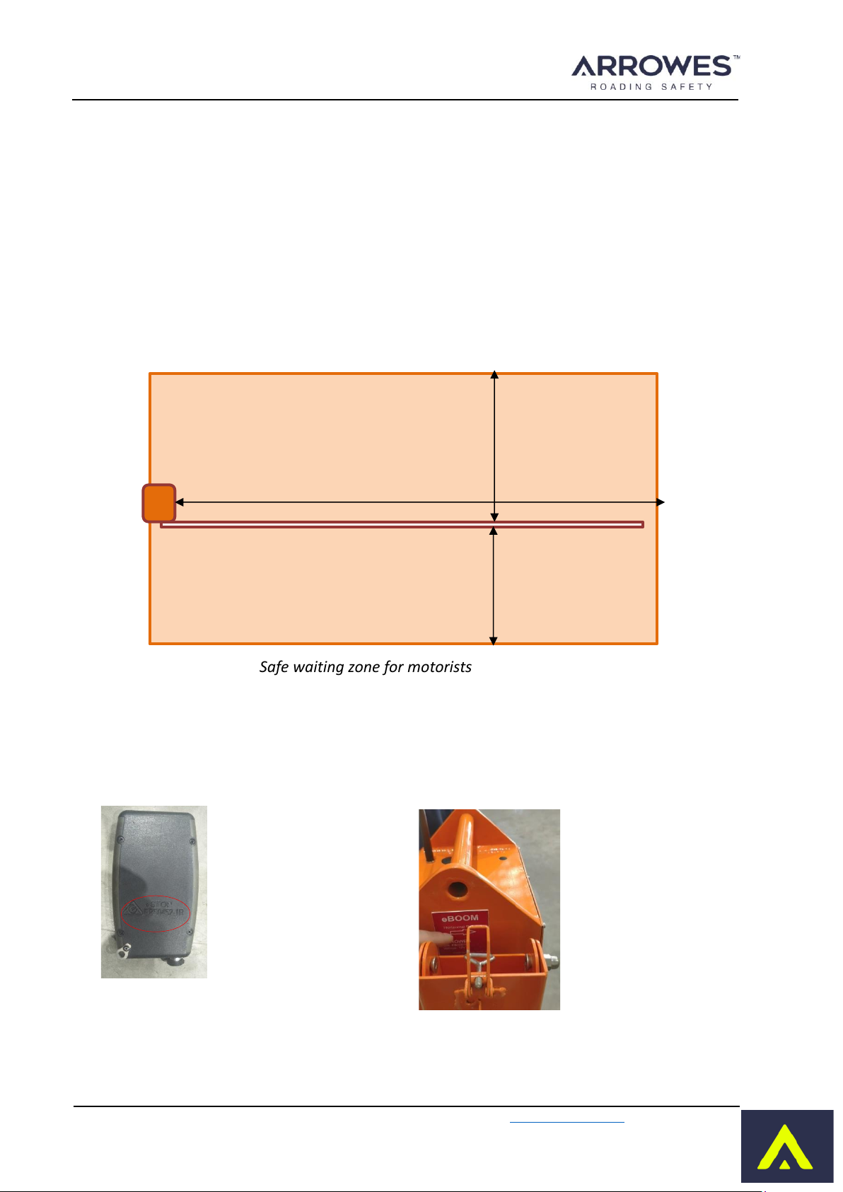
Safety Considerations.........................................................................................................................................6
eBOOM™SystemSpecifications........................................................................................................................7
Obstacle sensor specifications ...........................................................................................................................9
Labels..................................................................................................................................................................9
Key Features.....................................................................................................................................................10
Safety Features.................................................................................................................................................10
Unit Assembly/On-site Setup............................................................................................................................11
Operational Procedures....................................................................................................................................13
eBOOM™ Unit...............................................................................................................................................13
Hand Remote Controller –HRC....................................................................................................................14
LED indicators...........................................................................................................................................14
Modes of Operations................................................................................................................................15
Operational Steps.....................................................................................................................................15
Pairing the Handheld Remote Controller (HRC) to eBOOM™units .................................................................16
Un-pairing.....................................................................................................................................................16
Pairing HRC Unit1 (Left side of the HRC) .....................................................................................................16
Pairing HRC Unit2 (right side of the HRC)....................................................................................................17
Batteries - Care, Safe Handling and Charging...................................................................................................18
Maintenance.....................................................................................................................................................20
Calibration ........................................................................................................................................................20
Troubleshooting ...............................................................................................................................................21
Repairs & Servicing...........................................................................................................................................22
Safe Transportation ..........................................................................................................................................22
Material Life......................................................................................................................................................22
Warranty...........................................................................................................................................................22
eBOOM™ Operations & Service Manual

Arrow Emergency Systems | 17 Bailey Court Brendale Q 4500 | P: (07) 3881 3302 | www.arrowes.com.au Page | 4
eBOOM™ System Components Diagram
The eBOOM™structure consist of 5 main assembly parts:
1. The eBOOM™tripod which supports the whole structure
2. The eBOOM™tray which inserts into the tripod, holds the battery and provides a base for the
eBOOM™body
3. The eBOOM™body which holds the boom arm and raises it to vertical position, or lowers it to
horizontal position, according to remote controlled commands.
4. The Arrowes battery sits on the eBOOM™try battery compartment and powers the eBOOM™body.
5. The boom arm which inserts into the eBOOM™body arm holder.
Detachable
Boom arm Adjustable arm
length 2.1m –3.3m
Detachable
STOP sign
Arm holder with
locking latch
eBOOM™
Antenna
Detachable,
lockable battery
eBOOM™tray
eBOOM™tripod
Tripod leg locking pins
with levelling slots
Sandbag holder
LED flashers
Knob to adjust
the level of Tripod
Connector for
pairing cable
Power cable
Battery
Power
Switch
Ambient
light sensor
Boom arm
cable
Obstacle
sensor
Boom arm
holder
Alarm
Beeper
eBOOM™ Operations & Service Manual

Arrow Emergency Systems | 17 Bailey Court Brendale Q 4500 | P: (07) 3881 3302 | www.arrowes.com.au Page | 5
1. eBOOM™Body
2. eBOOM™arm with STOP sign 5. Battery Pack
6. Hand Remote
Control (HRC)
7. HRC Charging
and Pairing Cable
9. Battery
Charging cable 8. Dual port Wall
charger
10. Carry Case
Equipment Parts
Accessories
TM
Package Contents
Sl No Item Description Quantity
1 eBOOM™body 2
2 eBOOM™arm + STOP sign 2
3 Tripod 2
4 eBOOM™Tray 2
5 Battery Pack 2
6 Hand Remote Control (HRC) 2
7 Charging and Pairing cable 2
8 Dual port wall charger 1
9 Battery charging cable 2
10 Carry case 1
11 Operation and Service manual 1
3. Tripod 4. eBOOM™Tray
eBOOM™ Operations & Service Manual

Arrow Emergency Systems | 17 Bailey Court Brendale Q 4500 | P: (07) 3881 3302 | www.arrowes.com.au Page | 6
Safety Considerations
The eBOOM™has been developed as a response to a need for safer working conditions for traffic
controllers and roadwokers working in unpredictable live traffic sites. The eBOOM™can be used on its
own (must add the STOP sign) or as an integrated extension of the eSTOP (the STOP sign may not be
required in certain jurisdictions) when a physical barrier is required. It is designed to remove traffic
controllers from the hazard zones enabling traffic controllers to manage traffic movement within the
worksite from a safe distance. In order to reduce the risk to road workers, traffic controllers and road
users, the unit must always be operated effectively and consistently by authorized and trained operators.
The eBOOM™must be operated in accordance with all safety, operation and service instructions contained
in the manufacturer's operation and service manual. It is recommended that all operators read and
understand the manual before operating the eBOOM™. Operators must understand and comply with the
manufacturer's instructions as printed in the manual accompanying each eBOOM™in conjunction with
their respective Company’s Safe Work Method Statement.
The eBOOM™should only be operated by a designated, competent operator within the scope of on-site
operation parameters (such as the Company’s Safe Work Method Statement).
The eBOOM™shall be installed in a suitable location clear of obstructions. An appropriate risk assessment
shall be conducted to ensure the safe and suitable use of the eBOOM™. Examples of factors to consider
when assessing suitable location are safe distance from the traffic path, so that wide loads or turning
vehicles will not impact theunit, length of worksite,volume of traffic and topography. The eBOOM™should
be installed on a stable surface.
The eBOOM™system unit including the eBOOM™body, arm, tripod and battery box shall be kept clean. The
equipment shall be handled with care, the care you would extend to any electronic systems, such as your
radio.
The eBOOM™batteries shall be fully charged before operating the unit and must be used according to the
safety information.
The eBOOM™HRC and control procedures are built on the same platform as the eSTOP which has been
designed in accordance with Transport for NSW specification TSI-SP-081D, TDMR MRTS 264, Arrowes ISO
quality system and is ACMA approved. The application of the eBOOM™shall be in accordance with these
guidelines/standards as well as the respective company’s worksite risk assessment and Safe Work Method
Statements.
Any modifications made to the eBOOM™(unless by or approved by Arrowes) could compromise the
function and integrity of the eBOOM™and therefore the safe application of the units and voids the
warranty of the eBOOM™.
eBOOM™ Operations & Service Manual

Arrow Emergency Systems | 17 Bailey Court Brendale Q 4500 | P: (07) 3881 3302 | www.arrowes.com.au Page | 7
eBOOM™System Specifications
eBOOM™Unit
Obstacle detection range:
IP rating:
Voltage:
Operating amperage:
Battery (rechargeable)
Operating Hours (80% DoD)
Charging time:
Operating Temperature Range:
Hand Remote Controller (HRC)
RF operating frequency:
Configuration:
IP rating:
Battery (rechargeable):
Operating Hours (50% DoD)
Charging time:
Operating Current: (Transmitting)
Sleeping Current:
Operating Temperature Range:
+/- 25⁰, 350 cm
IP45
12v
1.7 A
30 A/H Lithium Iron phosphate
~18 Hours
5-6 Hours
-20 to 75⁰Celsius
2.4GHz
Single unit or dual unit control
IP65
3 A/H Lithium Polymer
~15 Hours
4-6 Hours
120mA
1mA
-20 to 85⁰Celsius
40 kg (allocated to full
21 kg
3.6 kg
3.5 kg
8.2 kg
3.5 kg
70 cm
Overall Device
Total mass per device (incl. batt, eBOOM™arm):
assembly)
eBOOM™body weight (max lifting weight):
eBOOM™tray weight:
eBOOM™arm weight:
eBOOM™Tripod weight:
eBOOM™Battery weight:
Tripod leg footprint radius:
Wind loading with 10 kg sandbag/leg: 100 km/h
425 cm
131 cm
211 cm x 90 cm x 22 cm
140 cm diameter
Dimensions
Maximum working height:
Minimum working height:
Dimensions when stored:
Base width, fully extended:
Arm length fully extended:
Arm length fully retracted:
331 cm
211 cm
Arm clearance above the ground (flat surface): 91 cm
eBOOM™ Operations & Service Manual

Arrow Emergency Systems | 17 Bailey Court Brendale Q 4500 | P: (07) 3881 3302 | www.arrowes.com.au Page | 8
Battery Specifications
eBOOM™ Unit
LiFePO4
12V
30 A/H
4.6 A
80%
~18 hours at 80% DoD
~17 hours of operation
Battery Type:
Voltage:
Full Capacity:
Max eBOOM™power consumption:
Depth of Discharge:
Operation time:
Low battery warning:
Life cycle:
IP Rating:
>800 at 80% DoD
IP54
Note: Battery cuts off after ~18 hours at 80% DoD of full capacity.
Low battery warning begins 1 hour before battery cut-off time.
Charger
Input:
Output:
Charge rate:
Battery Charging Time:
Hand Remote Controller (HRC)
AC100-240V
50/60Hz Max. 1.6A
DC 14.4V Max. 4.0A
~3A
5-6 hours from low battery
LiPo
3.7V
3 A/H
100mA
50%
~15 hours at 50% DoD
~14 hours of operation
Battery Type:
Voltage:
Full Capacity:
HRC power consumption:
Depth of Discharge:
Operation time:
Low battery warning:
Life cycle: >800 at 50% DoD
Note: Battery cuts off after ~15 hours at 50% DoD of full capacity.
Low battery warning begins 1 hour before battery cut-off
time.
Charger
Input:
Output:
Charge rate:
Battery Charging Time:
AC110-240V
50/60Hz Max. 0.35A
DC 5V Max. 2.0A
~0.6A
4-6 hours from low battery
eBOOM™ Operations & Service Manual

Arrow Emergency Systems | 17 Bailey Court Brendale Q 4500 | P: (07) 3881 3302 | www.arrowes.com.au Page | 9
Obstacle sensor specifications
The eBOOM™is fitted with obstacle detection system which detects any obstacle which may prevent the
eBOOM™arm from getting into horizontal position. This feature has been added to prevents injury or damage
to any person or vehicle who/which may be obstructing the movement of eBOOM™arm.
The obstacle sensor can detect obstacles within the range as specified below.
Safe waiting zone for motorists
Important: The area enclosed by the orange box as shown in the image above must be free of any obstacles.
Labels
Fully extended arm
360 cm
Safe waiting zone for motorists
eBOOM™
Body
150 cm
180 cm
Hand Remote
control
identification
number is located
at the back as
shown here
eBOOM™
identification number
is located at the side
of the eBOOM™body
facing the arm fitment
as shown here
eBOOM™ Operations & Service Manual

Arrow Emergency Systems | 17 Bailey Court Brendale Q 4500 | P: (07) 3881 3302 | www.arrowes.com.au Page | 10
Key Features
The eBOOM™is the first electronic boom barrier which weights 21kg, ensuring safe operations and complies
with OHS for lifting by an individual. Designed to remove the traffic controllers from the hazard zone and to
obstruct site entry, the eBOOM™can be used as a standalone or an integrated extension to eSTOP™. The key
features of the eBOOM™system are:
•Traffic controllers operate from a safe distance (up to 400m with option to increase distance).
•Can be implemented anywhere a stop/slow baton would normally be used.
•Can be operated with one controller (where there is clear line of sight) whilst the other takes a break
or is on rotation as the HRC can control 2 eBOOM™units.
•Environmentally robust, light weight, five-piece assembly, adjustable tripod legs for use at non flat
surfaces.
•IP65 rated compact Hand Remote Control (HRC).
•Hand Remote Control mimics eBOOM™states in real time.
•Wind load up to 100km/hr when used as per manufacturer’s guidance.
Safety Features
•When there is an obstacle, the eBOOM™arm stops lowering, the LED flashers and sound alert continue
its warning.
•Warning when the eBOOM™unit gets tilted by more than 200.
•The LED flashers flashes to alert drivers when the BOOM™is about to be deployed and continues flashing
lowered. The LED flashers are visible from 100m.
•The LED flashers are auto dimmed according to the surrounding light conditions (by reducing brightness
when it is dark ensuring the brightness does not become blinding).
•During operation, should communication failure occur between the HRC and the eBOOM™, the eBOOM™
arm will move to horizontal position after providing the 4 seconds warning.
•The eBOOM™arm automatically dislodge on impact. This prevents the eBOOM™from toppling over in
the event of any motorist crashing into the eBOOM™arm. The images below show how the arm gets
dislodged. The eBOOM™arm can be pushed back to its original position after the crash.
eBOOM™arm during normal operation. eBOOM™arm dislodged due to motorist crashing
into the arm.
eBOOM™ Operations & Service Manual

Arrow Emergency Systems | 17 Bailey Court Brendale Q 4500 | P: (07) 3881 3302 | www.arrowes.com.au Page | 11
Unit Assembly/On-site Setup
Pull the pin upwards to
release the leg
Extend the legs Pull the pin and align to the
suitable notch (usually the
middle notch).
Adjust each leg so that the
tripod stands stable on the
ground.
Open the sandbag holder
for each leg. Place
sandbags for each leg as
required to suit windload.
Insert the eBOOM™tray to
the centre column.
Secure the tray using
locking screw. Slide the eBOOM™body
onto the tray.
Maintain the same
orientation as shown. The
arrow sign indicates the
direction of the boom arm
movement in horizontal
position.
Lock latches to secure the
eBOOM™body.
Lock latches to secure the
eBOOM™body.
Insert Battery pack into the
Battery holder.
eBOOM™ Operations & Service Manual

Arrow Emergency Systems | 17 Bailey Court Brendale Q 4500 | P: (07) 3881 3302 | www.arrowes.com.au Page | 12
Lock latches on both sides
to secure the battery in
place.
Connect the Power cable.
Connector latches once
positioned in place.
Attach the STOP sign to the
eBOOM™arm. Note this
may not be required in
certain States and
applications.
Secure the STOP sign using
the lockable latches.
Extend the eBOOM™arm
to required length. Most
instances this is 3m.
Insert the eBOOM™arm
into the eBOOM™arm
holder.
Ensure the orientation of
the arm is such that the
STOP sign faces the
incoming motorists
Lock latches to secure the
arm
Attach the eBOOM™arm
cable to the eBOOM™as
shown.
Switch ON the eBOOM™
unit.
IMPORTANT: ensure eBOOM™ is stable and is weighted down with sandbags prior to operation. Minimal One
sand bag per tripod leg is required.
Ensure the arm is in vertical position (or removed from eBOOM™body) when moving the eBOOM™body or the
whole setup.
eBOOM™ Operations & Service Manual

Arrow Emergency Systems | 17 Bailey Court Brendale Q 4500 | P: (07) 3881 3302 | www.arrowes.com.au Page | 13
Operational Procedures
When the units have been assembled.
eBOOM™Unit
1. To switch ON the eBOOM™unit, push the small green power switch
behind the eBOOM™unit as shown in the image. The green LED light
will illuminate when powered ON. The eBOOM™unit will be controlled
by its master –the Handheld Remote Controller (HRC) once the HRC is
paired.
Modes –The unit runs in two modes, the ‘Test Mode’ and ‘Operation
Mode’.
Test Mode –when the unit first power ON, by default is in Test Mode.
In this mode, the HRC can be used to perform boom test. See HRC
procedures for LED test function, the LED flashers on the boom will flash
two times with Alarm Beeper beeping once.
Operation Mode –The unit can be activated (using HRC) to ‘Operation
Mode’. See HRC procedures for operation functions. When the unit first
activates, the LED flashers on the boom will flash for 4 seconds with
Alarm Beeper beeping for 4 seconds. Then the boom moves into
horizontal position with the LED flashers flashing on the boom, and the
Alarm Beeper stops beeping. In the horizontal position the LED flashers
remain flashing.
2. The eBOOM™unit is also fitted with a “Cut-Off Switch”. This is the Power Switch, located at the back
of the eBOOM™unit. This switch will turn Off the eBOOM™unit instantaneously as required. The
unit must also be Powered Off when not in use.
eBOOM™ Operations & Service Manual

Arrow Emergency Systems | 17 Bailey Court Brendale Q 4500 | P: (07) 3881 3302 | www.arrowes.com.au Page | 14
Hand Remote Controller –HRC
LED indicators –There are 3 types of LED indicators –Boom, Status, and Fault.
▪Boom indicators ❸❹ reflects the boom position/status of the paired eBOOM™units.
oRed –Boom arm is in Horizontal position
oYellow/Amber –Boom is in the waiting mode to move from vertical position to Horizontal position.
oGreen –Boom is in Vertical position
▪Status indicator ❿represents the states and faults of the overall system and indicates the following
colours:
oRed –when the HRC is off, Red indicates the HRC is charging. When the HRC is on, Red indicates
invalid press or fail pairing.
oBlue –once the HRC is powered on, the status indicator is Blue, which represents Test Mode.
oGreen –when the HRC is off, Green indicates the HRC is fully charged and stopped charging. When
the HRC is on, Green indicates valid press or the system is in Operational Mode.
oYellow/Amber –the Status will flash Yellow/Amber when the HRC battery is low.
oBlank/no colour –the HRC is powered off, if Pressing the buttons does not sound a beep then the
HRC is faulty or battery is completely dead
▪Fault indicators ❽❾ represents the states and faults of the respected paired unit.
oBlue –HRC is paired to an eBOOM™unit but communication fail (no connection, may need to re-
pair).
oPurple –The paired eBOOM™unit is tilted from its starting position after Activation. Or the Boom
arm is struck between vertical and horizontal position.
oGreen –The paired eBOOM™is communicating and operating normal.
oYellow/Amber –The paired eBOOM™battery is low.
oRed –The Paired eBOOM™unit has a fault in one of the LED flashers.
eBOOM™ Operations & Service Manual

Arrow Emergency Systems | 17 Bailey Court Brendale Q 4500 | P: (07) 3881 3302 | www.arrowes.com.au Page | 15
Modes
of Operations –The system runs in 2 modes, Test Mode and Operation Mode
▪Test Mode (Status LED blue) - When the HRC first power up it is in Test Mode, during this mode you can
pair/un-pair any eBOOM™units (refer to pairing section). Once it is paired to an eBOOM unit (and Fault
light is green), you can do a boom test and check the battery of the eBOOM™unit (refer eBOOM™
Battery section).
▪Operation Mode (Status LED green) - Once the HRC is paired and the Fault LED is green, the system can
be activated into Operation Mode. During this Mode, the operations of a Typical Traffic Signal can be
controlled, where the eBOOM™can be controlled to Horizontal Position (STOP)or vertical position (GO).
Operational Steps
1. Power On - Press and hold Power Button ❶for 5 seconds to power on Handheld Remote Control (HRC).
2. Fault indicators - When power is on Fault Indicator ❽❾ will show different colours according to the fault
hierarchy listed under Fault Reference ⓬when more than one fault occurs, the fault with lower hierarchy
will not be displayed until higher level fault(s) have been cleared.
3. Test - When first powered on, the HRC will starts in Test Mode and the Status Indicator ❿will show blue.
During Test Mode the HRC can be used to pair to a specific eBOOM™ unit (Refer to Pairing section). If the
HRC is paired to an eBOOM™ unit, the Fault Indicator ❽❾ will show Blue and change to green when
Synced to the paired eBOOM™ unit (allow up to 1 minute for the Fault light to turn green and get synced).
Once synced the HRC can be used to control the eBOOM™ unit. Pressing Buttons ❻or ❼ allows eBOOM™
to be tested (The flashing of the LED flashers on the boom along with a beeping sound ensures the Boom
is working).
4. Activation - When ready to operate the eBOOM™, hold down Activation Button ❷for 5 seconds to
activate the synced eBOOM™ units into Operation Mode, the Status Indicator ❿will then show Green.
The eBOOM™ will only operate when Fault Indicator is green.
5. Start-up - Upon switching from Test Mode to Operation Mode the eBOOM™ lantern will drop to horizontal
position after 4 seconds. The Hand Control will lock for 5 seconds and all buttons will not work during this
time. After 5 seconds the eBOOM™ unit is in Operation Mode.
6. Control Traffic Signals - Use Buttons ❺❻ or ❼to operate the eBOOM™ for traffic control. Use button
❻❼ to switch one or the other boom to vertical position. (Note: in order to set a boom to vertical
position, one or both booms must be in horizontal position first). Use button ❺to deploy boom (change
all booms to horizontal position). (Note: the LED flashers on the boom flashes along with beeping sound
for 4 seconds before the transition from undeployed (vertical position) to deployed (horizontal position).
After the boom is deployed (in horizontal position), the beeping sound stops, and the flashing of the LED
flashers continue. The LED indicators on the HRC reflect the eBOOM™ current status).
7. De-activation - In Operation Mode, holding Activation Button❷for 5 seconds returns the eBOOM™ units
to Test Mode.
8. Power off - In all modes, hold Power Button ❶for 5 seconds to commence power off. During Operation
Mode the HRC will not power off if the paired units lost sync (comms fail) to an eBOOM™ unit.
9. Switch off eBOOM™ power and disconnect battery cable before packing up.
Note: While in “off” mode, pressing “STOP” on the HRC will indicate battery life remaining. In the event of
forced power off is required on the HRC, pressing button “1” and “2” at the same time forces the HRC to
soft reset then powers off.
eBOOM™ Operations & Service Manual

Arrow Emergency Systems | 17 Bailey Court Brendale Q 4500 | P: (07) 3881 3302 | www.arrowes.com.au Page | 16
Pairing the Handheld Remote Controller (HRC) to eBOOM™units
The HRC can be paired to any eBOOM™ units. Once an eBOOM™unit is paired to an HRC it is stored in
memory, they will be automatically synced when powered up and ready for operation. By default, an HRC
is paired to 1 eBOOM™unit only. The HRC does not need to be paired at each use. This is only required
when the HRC is required to be paired to a different eBOOM™unit, when pairing 2 eBOOM™units to 1 HRC,
or when the eBOOM™has been mixed up with another HRC.
It is recommended to begin pairing by un-pairing all eBOOM™units from the HRC, this will reduce confusion
about which eBOOM™unit if already paired previously. Follow the steps below to begin the process.
Power on the HRC and the eBOOM™units, these must be in test mode for pairing (status LED ❿on
HRC is blue)
Un-pairing
Un-pairing is required if the HRC is already paired to an unknown eBOOM™and unable to sync. To do this
the HRC must be in test mode (status light is blue), the USB port must be disconnected from the eBOOM™
unit. Press and hold Unit1 “Go”button ❻for 5 seconds until a beep sounds. The HRC will flash a red
light on the Status Indicator, then Fault1 indicator will be blank, this indicates no eBOOM™unit is paired
to unit1 on HRC.
Repeat this un-pairing process (using Unit2 “Go” button) to un-paired Unit2 (left side of the HRC) if a second
eBOOM™is paired to Unit2 side. After un-pairing, Fault1 and Fault2 indicator will be blank, where no LED
is on.
Pairing HRC Unit1 (Left side of the HRC)
1. When in test mode, attach the USB cable from the top of the HRC unit to the USB
connector on the back of the eBOOM™unit as shown in the image.
2. Press and hold Unit1 GO button ❻for at least 4 seconds until a beep sounds. This
single beep indicates pairing has initiated and the button can be released.
When the pairing process is complete the HRC will sound either a fast double beep
as well as a green flashing light on the Status Indicator or a long single beep with
a red light on the Status Indicator.
•A fast double beep and green light indicates successful pairing. Fault1
indicator will go blue once it’s paired and changed to green when synced
(wireless communication between HRC and the eBOOM™is established) to
the paired unit (Note: allow 1 minute for the fault LED to change from blue
to green).
•A long, slow beep and red light on Status Indicator will indicate failed pairing.
The following issues may cause failed pairing:
1. USB cable is not attached properly
2. Unit is already paired on Unit2 (right side of the remote).
3. The eBOOM™ unit has no power/is not turned on (push green button at back of eBOOM™).
4. The HRC and eBOOM™ units are not in test mode
eBOOM™ Operations & Service Manual

Arrow Emergency Systems | 17 Bailey Court Brendale Q 4500 | P: (07) 3881 3302 | www.arrowes.com.au Page | 17
Once paired and synced (Fault1 indicator is Green, allow up to 60 seconds for this to turn Green), unplug
the USB cable, follow HRC Operational Procedures to operate the eBOOM™units.
Pairing an eSTOP lantern to work in conjunction with the eBOOM
An eSTOP lantern can be paired to Unit1 (same side on the HRC), this is done by
plugging the HRC to the lantern and repeat the same process above, using the
same side GO Button. When an eBOOM™and an eSTOP is paired to Unit1 of the
HRC, the eBOOM™and eSTOP are controlled and behave simultaneously. Fault
indicators will indicate Cyan colour instead of green, indicating 2 units are
paired. The same process can be done with HRC Unit2 GO button.
Pairing HRC Unit2 (right side of the HRC)
1. Repeat the pairing process by pressing Unit2 GO button ❼in Test Mode. Unit1 on the HRC must be paired
to an eBOOM™ before Unit2 can be paired.
Note: This is pairing a second eBOOM™to right side of the same HRC, this pairing setup allows 2 eBOOM™to
be controlled such that only 1 eBOOM™can be in vertical position at a time, if pairing as single unit
operations, only paired to Unit1 on each HRC with each eBOOM™. Unit2 on HRC is not used.
Indicates in Cyan colour when 2 unit
is paired to one control button.
eBOOM™ Operations & Service Manual

Arrow Emergency Systems | 17 Bailey Court Brendale Q 4500 | P: (07) 3881 3302 | www.arrowes.com.au Page | 18
Batteries - Care, Safe Handling and Charging
Running the units at low voltage for prolonged periods may degrade the battery’s integrity and will affect the
reliability of the system.
DO onlyusethe battery supplied. If replacement batteries are required, pleasecontact Arrowes for
the correctbattery.
DO store batteries in their original packing, in a dry place and at normal room temperature. Do charge
battery to 80+% if storing for long term. DO keep all batteries in a safe place away from Children and pets.
A. Charging the Batteries
1. The HRC Battery
The HRC can be charged from any USB device including the one attached to the eBOOM™ body (the screw
cap and USB connection are located at the back of the eBOOM™).
When the HRC is switched off and the USB is attached to a charging device, a red status LED indicates that
the battery is being charged. When the LED is green, the battery is fully charged. A flashing red LED
indicates that there is a battery fault and the battery should be replaced.
(Note: the battery charge indicator is only active when the remote control is switched off)
2. The eBOOM™ Battery
The eBOOM™is fitted with a light weight LifePo4 battery. To charge, remove the connector at the top box
of the battery and connect to the battery charger that is supplied by Arrowes.
The battery is charged through 240AC outlet charger, an indication LED on the charger shows the status
of charging.
-Red indicates charging
-Green indicates charging complete
Note: using any other non LiFePo4 charger could damage the battery and degrade the life expectancy
of the battery. If the battery/charger gives an odour, generates heat, becomes discoloured or deformed,
or in any way appears abnormal during use, immediate stop using the battery and chargers, then contact
your supplier.
B. Battery Status
1. The HRC
When the HRC is switched off and not charging, pressing button ❺will provide battery life status. Each
of the LED indicator light (❸❹)red, yellow and green represents 1/3 of the battery life (similar to a
battery bar), such that red+yellow+green indicates fully charged, yellow+green indicates 2/3and green
1/3 of battery life remaining.
(Note: the battery charge indicator is only active when the HRC is switched off)
2. The eBOOM™
The status of the eBOOM™ unit battery can be determined in 2 ways.
a. Remotely using HRC
When the system is in test mode and the eBOOM™ unit is sync to the HRC, press the stop button ❺, the
connected eBOOM™battery status will be indicated by the LED indicators (❸❹) red, yellow and green
represents 1/3 of the battery life (similar to a battery bar), such that red+yellow+green indicates fully
charged, yellow+green indicates 2/3 and green 1/3 of battery life remaining.
eBOOM™ Operations & Service Manual

Arrow Emergency Systems | 17 Bailey Court Brendale Q 4500 | P: (07) 3881 3302 | www.arrowes.com.au Page | 19
(No
te: if 2 units are paired to one side of the HRC, the battery status of the unit which has lower battery
charge remaining is indicated.)
The LED indicators will indicate battery status according to its respective paired units.
b. Directly on the Unit
The eBOOM™battery status can be determined on the unit directly by
pressing the button on the battery pack as shown. If the reading on the
display shows a value less than 11.5V, it means that the battery is running
low and must be charged.
C. Safe Manual Handling for Batteries
•Do not immerse the battery in water, and keep the battery in a cool dry surrounding.
•Do not use or leave the battery near a heat source such as fire or heater.
•Use only the battery charger specifically supplied when recharging.
•Do not reverse the position and negative terminals.
•Do not connect the battery directly to an electrical outlet.
•Do not discard the battery in fire or a heater.
•Do not short-circuit the battery by directly connecting the positive and negative terminals with metal
objects.
•Do not strike, trample or throw the battery.
•Do not directly solder the battery and pierce the battery with a nail or other sharp objects.
•Do not use or leave the battery at high temperature. Otherwise, it can overheat or its performance will
be degenerate and its service life will be decreased.
•Do not use the battery in a location where static electricity and magnetic field is high, otherwise the
safety devices may be damaged.
•If the battery has leaked, and the electrolyte gets into the eyes, do not rub the eyes, instead, rinse the
eyes with clean water, and immediately seek medical attention. Otherwise, it may injure eyes.
•If the battery gives an odour, generates heat, becomes discoloured or deformed, or in any way
appears abnormal during use, recharging or storage, immediately remove it from the device or battery
charger and stop using it.
•In case the battery terminals are dirty, clean the terminals with a dry cloth before use. Otherwise
suboptimal performance may occur due to the poor connection with the instrument.
•Be aware discarded batteries may cause fire or explode, tape the battery terminals to insulate them.
•The lithium batteries should be recycled. Look for companies who will buy them or your local battery
recycling centre for disposal options.
eBOOM™ Operations & Service Manual

Arrow Emergency Systems | 17 Bailey Court Brendale Q 4500 | P: (07) 3881 3302 | www.arrowes.com.au Page | 20
Maintenance
1. The low Battery indications are provided on the HRC for both HRC and the synced units. Ensure
the units don’t run on low battery for long time. Running the HRC or the units at low voltage for
prolonged periods may degrade the battery’s integrity and will affect the reliability of the system.
2. Turn OFF all the battery units when not in use (both the eBOOM™unit and the HRC unit).
3. The eBOOM™should be wiped with a damp cloth to remove dirt/dust which may form.
IMPORTANT –As a safety precaution,in case of communicationfailure/out of range, the eBOOM™will
default to Horizontal position.
Calibration
Calibration is used to realign the packed,vertical and horizontal positions of the boom
arm.
Firstly turn off the unit and remove the 10 screws off the front the eboom. Secure the front panel with tape
so that it doesn’t fall down. With the front panel removed be make sure that the back of the eBOOM is
hooked onto the battery tray from the front and latched on the battery tray on the back so that it doesn’t
tip over during calibration.
After opening you will see a calibration switch.
With the eBOOM in test mode press the calibration switch. The eBOOM will now release the motor for the
boom arm to move freely.
Once pressed you have 10 seconds to move the eBOOM arm to the pack position as shown below.
When 10 seconds has elapsed the eBOOM will beep once indicated it has saved the packed position.
After the first beep in the previous step quickly move the boom arm the vertical position. You will have 10
seconds to move the arm to the desired vertical position and then the eBOOM will beep twice indicating it
has saved the vertical position.
Front
Back
Front
Back
eBOOM™ Operations & Service Manual
Table of contents
Other ARROWES Safety Equipment manuals