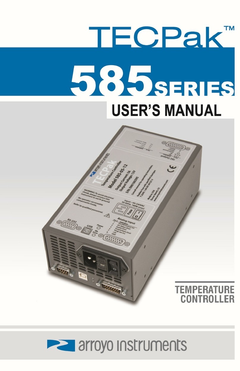
Arroyo Instruments TECPak 586 Series User manual


Page 2 · 586 TECPak User’s Manual
Table of Contents
Introduction .............................................................................................................3
Safety Terms and Symbols.....................................................................................4
Quick Start...............................................................................................................6
Installation ...............................................................................................................7
Operating Modes ....................................................................................................9
Settings..................................................................................................................10
Arroyo Control .......................................................................................................14
Interfacing to the TECPak .....................................................................................14
Connecting to the TECPak ...................................................................................16
Installing the USB Drivers .....................................................................................16
Saving and Restoring Configurations...................................................................16
Using the TEC Interlock/LED Interface .................................................................17
TEC Control Modes...............................................................................................19
Using the Current Limit .........................................................................................19
Using the Voltage Limit .........................................................................................19
Understanding the Sensor Inputs.........................................................................20
Applying Sensor Limits .........................................................................................20
Selecting the Fixture..............................................................................................21
Working With Thermistors.....................................................................................22
Working With RTDs ...............................................................................................23
User Calibration of Resistance Sensors ...............................................................25
Controlling the Temperature Rate of Change ......................................................25
Gain Control and the PID Loop.............................................................................26
Using the AutoTune Function ...............................................................................26
External Fan Control .............................................................................................28
Resistive Heaters and Heat/Cool Only Modes .....................................................28
Correcting the TEC Voltage Measurement...........................................................29
Specifications ........................................................................................................31
Error Messages .....................................................................................................33
Mechanical Drawings............................................................................................35
Calibration, Maintenance and Service..................................................................37

586 TECPak User’s Manual · Page 3
Introduction
Thank you for choosing the 586 TECPak from Arroyo Instruments. Your
TECPak is a combination of leading edge technology combined with years of
experience in the field of temperature control, and based on the proven designs
found in the 5300 Series TECSources.
The TECPak was design for system integration applications, or simply where a
user interface like that found on the 5300 Series TECSources is not required or
desired. With high TEC power options, a USB computer interface, and small
footprint, the TECPak will fit into almost any temperature control application.
The 586 TECPak offers all the features you would expect from a modern
temperature controller, including:
Support for thermistor, LM335, and RTD sensors.
4-wire measurement mode for RTD sensors.
AutoTune for automatic PID parameter calculation
0.004°C temperature stability
0.01°C resolution for both set point and actual temperatures
What’s in the Box
Along with the 586 TECPak itself, a CD with electronic copies of this manual, the
Computer Interfacing Manual, and USB drivers are included. For USA
customers, a power cord is included. For non-USA customers, an IEC-60320-
C13 rated AC power cord must be provided.
Accessories
Arroyo Instruments also sells several accessories designed to work with the
TECPak. These include:
TECSource Cable, 30A, 2m (p/n 1264)
This cable has 17W2 male/female connectors for interfacing to the
LaserMount or other connectorized fixtures, includes wiring for the fan
interface, and supports up to 30A of TEC current. A pigtailed version of
this cable is available as p/n 1265.
TECSource Cable, 17W2 to DB15, 15A, 2m (p/n 1264-DB15)
This cable has a 17W2 male connector for the instrument end and a
DB15 female connector for the mount end, and is used to connect the
5400 to mounts that utilize the DB15 TEC connector, such as the 274
TECMount. The 1264-DB15 supports up to 15A of TEC current.
Pak Series Rack Mount Kit, 3 or 5 units (p/n 1402C-RM)
For installing your TECPak or LaserPak into a standard 19” rack. The

Page 4 · 586 TECPak User’s Manual
kit accepts either 3 units for a 2U installation, or 5 units for a 3U
installation.
10kΩThermistor (p/n 1600-10K)
100ΩPlatinum RTD (p/n 1600-100RTD)
USB Cable, 3m (p/n 1201)
Safety Terms and Symbols
The following safety-related terms are used in this manual:
Warnings (noted by the WARNING heading) explain dangers that
could result in physical injury or death;
Cautions (noted by the CAUTION heading) explain conditions that
could result in damage to the instrument, other equipment, or your
device.
Notes (noted by the NOTES heading) are not safety-related, and are
intended simply to point out important information.
If, at any time, any of the following conditions exist, or are suspected of existing,
discontinue use of the unit until it can be inspected by qualified service
personnel:
Visible damage to the unit, including damage or stress caused during
product shipment;
Storage of the unit outside the standard storage temperature or
humidity rating, or prolonged storage under harsh conditions;
Failure to operate properly.
If needed, contact your distributor or Arroyo Instruments for service or repair to
ensure the safety of the product is maintained.
Symbols
Power Off Power On
Caution, refer to manual Earth ground
Caution, risk of electric shock

586 TECPak User’s Manual · Page 5
General Warnings
WARNING
This instrument is intended for use by qualified
personnel who understand the shock and laser hazards
and are familiar with safety procedures required to avoid
injury. Read this manual completely before attempting
to use this product.
WARNING
To avoid electrical shock, ensure a 3-prong power cord
is used, and is plugged into a earth-grounded
receptacle. Failure to do so can result in severe injury or
death.
CAUTION
There are no user-serviceable parts inside. All service
and repair work shall be done by Arroyo Instruments or
personnel authorized by Arroyo Instruments.
Modifications done by non-authorized personnel will
void the warranty. Please see the Service section later
in this manual for instructions on how to obtain service
for this instrument.

Page 6 · 586 TECPak User’s Manual
Quick Start
The 586 TECPak was designed with ease of use in mind, and you will likely
have little need for this manual for almost all of the features the unit offers. This
section will show how you can quickly get the unit up and running in almost no
time.
The TECPak has a universal input power supply, accepting 90 to 240 VAC, and
50 or 60 Hz. This covers all conventional power worldwide, but ensure your AC
power meets these requirements.
Plug the AC cord into the unit and into the wall outlet. Turn on the power switch
located on the IPC, and the unit will power up. The AC Power LED should light,
and the On / Error LED should remain dark.
Install the Arroyo Control software located on the CD that came with the
instrument (it can also be downloaded from our web site), located in the
Software folder on the CD. Once the software is installed, plug the instrument
into the USB interface. The instrument may also ask for drivers, which are also
found on the CD.
Launch Arroyo Control, and in the TECSource panel (if one is not visible, click
Add Panel in the lower right of the window, and click Add a TEC Panel), select
the communications port to which your TECPak is connected. This will usually
be the highest numbered port in the list. Click Connect, and Arroyo Control will
begin controlling the TECPak. Once connected, you will be able to adjust
settings, limits, and turn the output on or off.
Next, connect the cable between your LaserMount or other fixture and the
Output connector of the TECPak. We recommend using our cables as they
have been designed to work well with the TECPak. If using your own cables,
ensure they have been properly wired according to the pin-out of the TECPak
and your fixture.
Finally, set the set point to an appropriate temperature and turn the output on.
You will see the voltage and current begin driving the fixture to the set point you
have chosen. Depending on the thermal size of your fixture, it may take seconds
or several minutes to reach the set point.
If you notice the temperature is oscillating around the set point and not
stabilizing, you may need to adjust the Gain setting in the Settings… dialog.
You can use the AutoTune feature to automatically calculate the best PID values,
or select from a set of eight factory preset values that typically cover most
applications. To use the factory gains, if the temperature is quickly jumping up
and down, the Gain will typically need to be reduced. If the temperature is slowly
moving up and down, try a higher Gain. You may need to experiment with

586 TECPak User’s Manual · Page 7
several gain settings to find the ideal value, and for even finer control, you can
set the Gain to PID and directly set the PID control values.
Installation
Installation of the 586 TECPak is very straightforward, as the quick start section
above illustrated. This section will provide additional details and considerations
for installing your TECPak.
After unpacking the unit, make sure all packing materials have been removed
and nothing obscures the ventilation ports on the front and back of the unit.
The TECPak has a universal input power supply, accepting 90 to 240 VAC, and
50 or 60 Hz. This covers all conventional power worldwide, but ensure your AC
power meets these requirements.
Powering Up the Unit
Connect the AC power cord to the unit. Turn the power switch, located on the
AC power input power connector, into the on (|) position. The unit will go
through a quick power-up self-test, and return to the last known operating state.
The AC Power LED will light up, and the On / Error LED should remain dark until
the TEC output is turned on (if Automatic Output On has been enabled, the On
LED may light without user intervention).
CAUTION
Do not exceed 250VAC on the line input.
It is critical to maintain the proper voltage input into the
unit. If the actual voltage exceeds 250VAC, damage to
the unit may occur.

Page 8 · 586 TECPak User’s Manual
Ventilation
The TECPak has vent holes on the front and rear and sides of the unit. You must
not block these vent holes, or overheating may occur, causing damage to the
unit.
Rack Mounting
A rack mount kit (p/n 1402C-RM) for standard 19” racks is available for the 586
TECPak, and supports the rack mount of up to three units in a 2U high opening.
The units primarily ventilate from the front and rear, with some ventilation on he
sides, so some air gap is required to the sides of the unit to ensure proper air
flow. No air gapping is required above or below the units, and they can be rack
mounted immediately above other equipment (no rack spacers required).
Warm-up and Environmental Considerations
In order to achieve the highest level of accuracy, the TECPak should be
powered on for at least one hour prior to taking measurements. In addition,
ensure that the unit is not operating outside the ambient temperature range or
humidity conditions.
CAUTION
Do not operate the unit above +40°C ambient, and
ensure the instrument is properly ventilated, or the unit
may overheat and possible damage to the instrument
may occur.

586 TECPak User’s Manual · Page 9
Operating Modes
Control Modes
The TECPak offers three control modes: constant temperature mode (T Mode),
constant resistance mode (R Mode), and constant current mode (Ite Mode).
Changing the control mode can only be done through the computer interface,
either through Arroyo Control, or by sending the appropriate TEC:MODE
command.
Constant temperature mode uses the sensor constants to calculate the
resistance of the sensor at the desired or actual temperature.
While most users will only need the temperature control mode, the constant
resistance mode allows you to bypass the sensor equation and directly select
the sensor set point. This can be useful when only the desired sensor value is
known, or when the sensor-to-temperature conversion values are not available
for your sensor.
Using Limits
The TECPak supports three different types of limits: temperature, sensor, and
current. There is both a temperature high and temperature low limit, and if the
actual temperature exceeds either of these limits, the output will be shut off.
Likewise, both high and low limits exist for the sensor (R limits), and the output
will be shut off if the sensor measurement exceeds either of these limits.
It is important to properly set these limits to protect your device from damage. If
you are uncertain on how to set the limits, please consult with your local
distributor or directly with the factory.

Page 10 · 586 TECPak User’s Manual
Settings
All parameters of the TECPak can be viewed and changed over the computer
interface.
Most parameters can be changed using a standard command, as defined in the
Computer Interfacing Manual or through the Settings… dialog within Arroyo
Control. Below is a list of the most common settings and the corresponding
computer command to change it.
Name Description Factory
Default
Computer
Command
Basic Settings
Mode This set the operating mode (T
Mode, R Mode, or Ite Mode) of
the temperature controller.
T Mode TEC:MODE
Mount Specify the mount connected to
the TECPak. If using a
LaserMount, select the
appropriate model. Otherwise,
select User Defined.
User
Defined
TEC:MOUNT
I Lim I Lim sets the current limit of
the temperature controller. The
limit should be set to a value
that is suitable for your Peltier
device.
3A TEC:LIM:ITE
Gain Gain controls the response of
the temperature controller.
Select PID for direct access to
the PID parameters. Read more
on setting gain below.
30 TEC:GAIN
PID P The proportional term of the
PID loop. Will only be available
if Gain is set to PID.
1 TEC:PID
PID I The integral term of the PID
loop. Will only be available if
Gain is set to PID.
0.01 TEC:PID
PID D The derivative term of the PID
loop. Will only be available if
Gain is set to PID.
0 TEC:PID

586 TECPak User’s Manual · Page 11
Name Description Factory
Default
Computer
Command
Sensor Sets the temperature
measurement sensor. Can be
Therm 100uA, Therm 10uA,
Therm, LM335, RTD, or RTD (4-
wire).
Therm
100uA
TEC:SENS
Active
Sensor
Selects sensor 1 or sensor 2 for
feedback control.
1 TEC:ACTIVESENS
T-Low Lim T-Low Lim is the lower
temperature limit. If operating in
T Mode and the actual
temperature drops below this
value, the output will be turned
off. Temperature limits not
monitored in R Mode or Ite
Mode. Limit monitoring can
also be disabled in software
(see TEC:ENAB:OUTOFF
command).
-99°C TEC:LIM:TLO
T-High Lim T-High Lim is the upper
temperature limit. If operating in
T Mode and the actual
temperature rises above this
value, the output will be turned
off. Temperature limits not
monitored in R Mode or Ite
Mode. Limit monitoring can
also be disabled in software
(see TEC:ENAB:OUTOFF
command).
125°C TEC:LIM:THI
R-Low Lim R-Low Lim is the sensor low
limit. If operating in R Mode and
the actual sensor measurement
drops below this value, the
output will be turned off. R
limits are not monitored in Ite
Mode. Limit monitoring can
also be disabled in software
(see TEC:ENAB:OUTOFF
command).
0.01kΩTEC:LIM:RLO

Page 12 · 586 TECPak User’s Manual
Name Description Factory
Default
Computer
Command
R-High Lim R-High Lim is the sensor high
limit. If operating in R Mode and
the actual sensor measurement
exceeds this value, the output
will be turned off. R limits are
not monitored in Ite Mode. Limit
monitoring can also be
disabled in software (see
TEC:ENAB:OUTOFF
command).
45kΩTEC:LIM:RHI
Tol Time Tolerance time is the amount of
time, in seconds, that the actual
temperature must be within the
set point temperature +/- the
Tol Temp value for the unit to
be considered in tolerance.
5 seconds TEC:TOL
Tol Temp Tolerance temperature is a
temperature band (in °C)
around the set point
temperature. When the actual
temperature is within this band
for longer than the Tol Time
setting, then the unit is
considered to be in tolerance.
0.1°C TEC:TOL
H/C Mode This selects the heating and/or
cooling mode of the TECPak.
See the section below titled
“Resistive Heaters and
Heat/Cool Only Modes” for
more information.
Heat/Cool TEC:HEATCOOL
Ext Fan This selects the voltage for the
auxiliary fan power supply. See
the External Fan Control section
below for more information.
Off TEC:FAN
Ext Fan Pwr When Ext Fan is set to Custom,
this sets the specific fan voltage
from 4.0 to 12.0 volts. See the
External Fan Control section
below for more information.
12.0 TEC:FAN

586 TECPak User’s Manual · Page 13
Name Description Factory
Default
Computer
Command
Ext Fan
Mode
Controls when the fan operates.
See the External Fan Control
section below for more
information.
Auto TEC:FAN
Ext Fan Off When Ext Fan Mode is set to
Delay, this setting defines the
number of minutes to delay
turning off the fan after the TEC
output has been turned off. See
the External Fan Control section
below for more information.
5 minutes TEC:FAN
Cable R The resistance of the cable and
connectors, in ohms. This
setting allows for accurate
voltage measurement at the
TEC by removing the voltage
loss of the cable.
0.0080ΩTEC:CABLER
T Rate Selects a desired temperature
ramp rate in degrees Celsius
per minute. Set to 0.0°C/min to
disable rate limiting.
0.0°C/min TEC:TRATE
Sensor Settings
ThermA A term in thermistor equation. 1.12924E-03 TEC:CONST
ThermB B term in thermistor equation. 2.34108E-04 TEC:CONST
ThermC C term in thermistor equation. 0.87755E-07 TEC:CONST
RTD A A term in the RTD equation. 3.98480E-03 TEC:CONST
RTD B B term in the RTD equation. -0.58700E-06 TEC:CONST
RTD C C term in the RTD equation. 4.00000E-12 TEC:CONST
RTD R0R
0term in the RTD equation. 100.00 TEC:CONST

Page 14 · 586 TECPak User’s Manual
Arroyo Control
While most of the settings of the TECPak can be changed over the computer
interface using your own program (see the Computer Interfacing Manual for
more detail), in many cases you simply want to operate the instrument from the
PC like any other bench-top instrument.
As mentioned earlier in this manual, Arroyo Control is a free software
application that gives you 100% operating control of the TECPak, allowing you
to change limits, settings, and set points, as well as monitor the operation of the
instrument. You can install Arroyo Control from the CD or download it from our
web site (go to the Software section).
Interfacing to the TECPak
The TECPak features just two connections (in addition to the input power
connector): the USB and output connector. Both are located on the front of the
unit. In addition, the front of the unit has the input power connector and two
status LEDs. The rear of the unit has the cooling fan, which pulls air in and
exhausts it out the front.
586 TECPak Interface Panel

586 TECPak User’s Manual · Page 15
TEC Output Connector
The Output connector is a female 17W2, and has the following pin-out:
Pin Description Pin Description
A1 TE (+) A2 TE (–)
1 LED/Interlock+ 8 LED/Interlock –
2 VTE Sense+ 9 VTE Sense –
3 Sensor 1 – 10 Remote Sensor 1 –
4 Sensor 1+ 11 Remote Sensor 1+
5 n/c 12 n/c
6 Sensor 2– 13 Earth Ground
7 Fan+ 14 Sensor 2+
15 Fan – (Signal Ground)
Output Connector (17W2 Female)
Inverting the TE Output
In the event the polarity of the TE pins is backwards, it is possible to reverse the
direction of the TEC current by using the TEC:INVERTITE command. While not
recommended as it can lead to confusion when the controller is used later in
properly wired setups, this allows for correct operation of system when the TE
pins are wired backwards and rewiring is not possible or feasible.
USB Connector
The USB connector is a standard Type B female connector, and can be plugged
into any USB 1.1 or USB 2.0 port. For more information on using the USB
interface, see the Computer Interfacing Manual which is included on the CD
that accompanied this product.
LED Indicators
There are three LEDs: the upper green AC Power LED that is lit whenever the AC
power is turned on; and a red Error LED that will light when an error has
occurred, and a blue Output On LED that will light whenever the TEC output is
on.

Page 16 · 586 TECPak User’s Manual
Connecting to the TECPak
Arroyo Instruments carries two cable assemblies specifically designed for
connecting the 586 TECPak to temperature controlled fixtures or devices. The
1264 TECSource Cable (not included) is a two meter cable, designed for use
with Arroyo Instruments mounts, and has 17W2 connectors on both ends.
For custom applications, a two-meter cable with a male 17W2 on one end and
stripped and tinned leads on the other is available as part number 1265.
See the manual for your fixture for additional safety and operational information.
Installing the USB Drivers
Using the TECPak via USB is just as simple as using the serial port. In fact, once
you have installed the USB drivers, the instrument will appear as a virtual serial
port that you can use just like a normal serial port.
To install the drivers, simply plug in the instrument to your computer. When the
Add New Hardware wizard appears, insert the CD you received with the TECPak
and follow the on-screen instructions.
Once the drivers are installed, to determine the COM port number, go to Control
Panel and select System. Once the System Properties dialog appears, choose
the Hardware tab then click on the Device Manager button. When the Device
Manager appears, click on the plus sign to the left of Ports. The port identified
as an USB Serial Port is the TECPak. In the event you have multiple TECPaks
plugged in simultaneously, you will need to experiment to see which instrument
was assigned to which port. For example, you could change the set point when
the output was off to see which unit’s set point changed.
Saving and Restoring Configurations
Using the the *SAV and *RCL commands over the computer interface, TECPak
allows you to save up to four configurations. Each configuration will store all of
the instrument settings (except scripts and user calibration data), and allow you
NOTE
Connections to the 586 TECPak and the fixture must be
secure. Tighten any screws on the 17W2 connectors,
and make sure all connections are in good condition.

586 TECPak User’s Manual · Page 17
to quickly recall them. This is particularly useful when the instrument is used in
multiple setups, and the particular configuration of each setup can be stored
and later recalled for a quick reconfiguration.
To store a configuration, use the *SAV command over the computer interface.
To recall a configuration, use the *RCL command.
Using the TEC Interlock/LED Interface
The TECPak features a combination digital input/digital output/LED interface on
pins 1 & 8. The most common use of this interface is to turn on an LED when the
output is on, but other functions can be assigned to the LED operation. It can
also be used as a digital input to remotely control the on/off state of the channel,
or to act as an interlock function.
The TEC:DIO:INMODE command controls how the digital input is to be used:
Off – ignore the digital input
Interlock – prevent operation until circuit is closed
Output On – turn on the output when circuit is closed
You can also invert the logic level of the input using the same command. For
example, if the function was inverted, and set to Output On, the output would
turn on when the circuit was opened.
Of special note is the Output On function: this action is taken only on a transition
from open to closed state of the circuit. This allows the output to be turned off
via the front panel or remote commands even when the circuit is closed.
You can also drive an LED using the output function setting accessed via the
TEC:DIO:OUTMODE command. For example, this could be used to turn on a
LED whenever the output is on, but there are several functions to choose from:
Off – turn the output off (this is the default setting)
On – turn the output on
Out On – whenever the channel output is on
Stable – when the channel output has stabilized
T Limit – the temperature exceeds the limits
I Limit – operating at the current limit
Remote – the unit is in remote mode
V Limit – operating at the voltage limit
Like the digital input, the output function can be inverted for active low signals.

Page 18 · 586 TECPak User’s Manual
For purposes of the TEC:DIO commands, this dual-purpose input/output
function is considered both digital input 1 and digital output 1.
Closing the Circuit
A +5V supply is used to bias the LED and goes through a 200Ωseries resistor.
To close the circuit, there must be 4.5V or less across pins 1 and 8. A short
circuit can be used, but an LED can optionally be connected.
Depending on the type of LED, no resistor, series resistor, or parallel resistor can
be used. Red, green, and yellow LEDs may require no resistor. Blue LEDs are
too efficient to be wired with a series resistor and must use the parallel resistor
option.
When using a series resistor, the higher the resistor value, the dimmer the LED.
Do not use too high of a resistance value or it may always register as an open
circuit.
When using a parallel resistor, the lower the resistor value, the dimmer the LED.
Red, green, and yellow LEDs will typically use higher resistances (1kΩor more),
while blue LEDs will use smaller resistor values (typically around 100Ω).
No Resistor Series Resistor Parallel Resistor
Isolation and Multiple Interlocks
The LED/TEC Interlock Interface is electrically isolated from all other control
signals, and interlocks from multiple TECPaks can be wired in parallel through a
single switch.
Pin 8
Pin 1
Pin 8
Pin 1
Pin 8
Pin 1

586 TECPak User’s Manual · Page 19
TEC Control Modes
The TECPak offers three TEC control modes: constant temperature mode (T
Mode), and constant resistance mode (R Mode), and constant current mode (Ite
Mode).
Changing the control mode is done using the TEC:MODE commands.
Constant temperature mode uses the sensor constants to calculate the
resistance of the thermistor at the desired or actual temperature.
While most users will only need the temperature control mode, the constant
resistance mode allows you to bypass the sensor equation and directly select
the sensor set point. This can be useful when only the desired sensor value is
known, or when the sensor-to-temperature conversion values are not available
for your sensor.
Using the Current Limit
The current limit in the TECPak is used to limit the amount of current that is
delivered to the mount. Because the TECPak has a hardware current-controlled
output, the current will not exceed the limit at any time in any mode. Set the limit
by using the TEC:LIM:ITE command.
Operating at the current limit is common, especially when transitioning from one
temperature to another. There is no harm or danger to the TECPak when
operating in this condition.
Using the Voltage Limit
The TECPak also supports a software-controlled voltage limit. In most
applications, the voltage limit is not needed, and can be left at the maximum
setting, as the TECPak is a current output controller, and the voltage simply
goes to whatever voltage is required by the TEC. By default, the voltage limit is
set to the rating of the instrument plus 2 volts, so it will not engage unless
adjusted lower.
It is important to understand that the voltage limit is a software-imposed limit,
which means that the response time to over-limit conditions can be several
hundred milliseconds or longer. During that response time, a significant over-
voltage condition can persist. However, with a properly set current limit, the
device is still protected from excessive power conditions, and should not pose

Page 20 · 586 TECPak User’s Manual
any danger to TEC devices due to the relatively short duration of the over-
voltage condition.
For the voltage limit to engage, the following conditions must be met:
TEC:LIM:V is set to 1V or higher
At least 25mA of TEC current
The second point is to ensure there is a sufficient current signal that can be used
in calculating the load impedance (and therefore limit the current to correctly
limit the voltage).
Operating at the voltage limit is common, especially when transitioning from one
temperature to another. There is no harm or danger to the TECPak when
operating in this condition.
Understanding the Sensor Inputs
The 586 TECPak supports two primary sensor inputs, and either input can be
used to control the temperature of your device or mount.
The two sensor inputs support:
Sensor 1 supports thermistor, LM335, RTD, and 4-wire RTD sensors.
Sensor 2 supports thermistor and RTD sensors.
One or both can be enabled for monitoring, but only one can be used for the
control loop. The primary sensor selected for the control loop is called the
Active Sensor. Use the TEC:ACTIVESENSOR command to change the active
sensor.
The TECPak has no auxiliary sensor inputs.
For best system performance, unused sensor inputs should be disabled.
Applying Sensor Limits
With the wide range of sensor connectivity options, the 586 TECPak is designed
with a series of temperature protection limits and options to allow for flexibility
when meeting the demands of different applications.
Each sensor has a dedicated high and low temperature limit, set using the
TEC:LIM:THI or TEC:LIM:TLO commands. When the temperature input exceeds
these limits, that sensor is considered to be in limit, either high or low. Limit
This manual suits for next models
4
Table of contents
Other Arroyo Instruments Temperature Controllers manuals
Popular Temperature Controllers manuals by other brands

Middleby Marshall
Middleby Marshall 37626 Installation, programming and troubleshooting instructions

Auber
Auber WS-1500ES Operation & instruction manual

Yudian
Yudian AI-218 user manual

HTW
HTW ECO-THERMAL owner's manual

La Crosse Technology
La Crosse Technology TX141TH-Bv3 quick start guide

Omron
Omron E5CN-FR manual

Autonics
Autonics TM-Q02H Technical support manual

Honeywell
Honeywell C7776A installation instructions

S+S Regeltechnik
S+S Regeltechnik THERMASGARD RTF Series Operating Instructions, Mounting & Installation

Jaga
Jaga BRIZA 12 manual

MISUMI
MISUMI MTCTR manual

Ropex
Ropex RESISTRON RES-403 operating instructions