manuals.online logo
Brands
  1. Home
  2. •
  3. Brands
  4. •
  5. ARS
  6. •
  7. Automobile Accessories
  8. •
  9. ARS JL Pro User manual

ARS JL Pro User manual

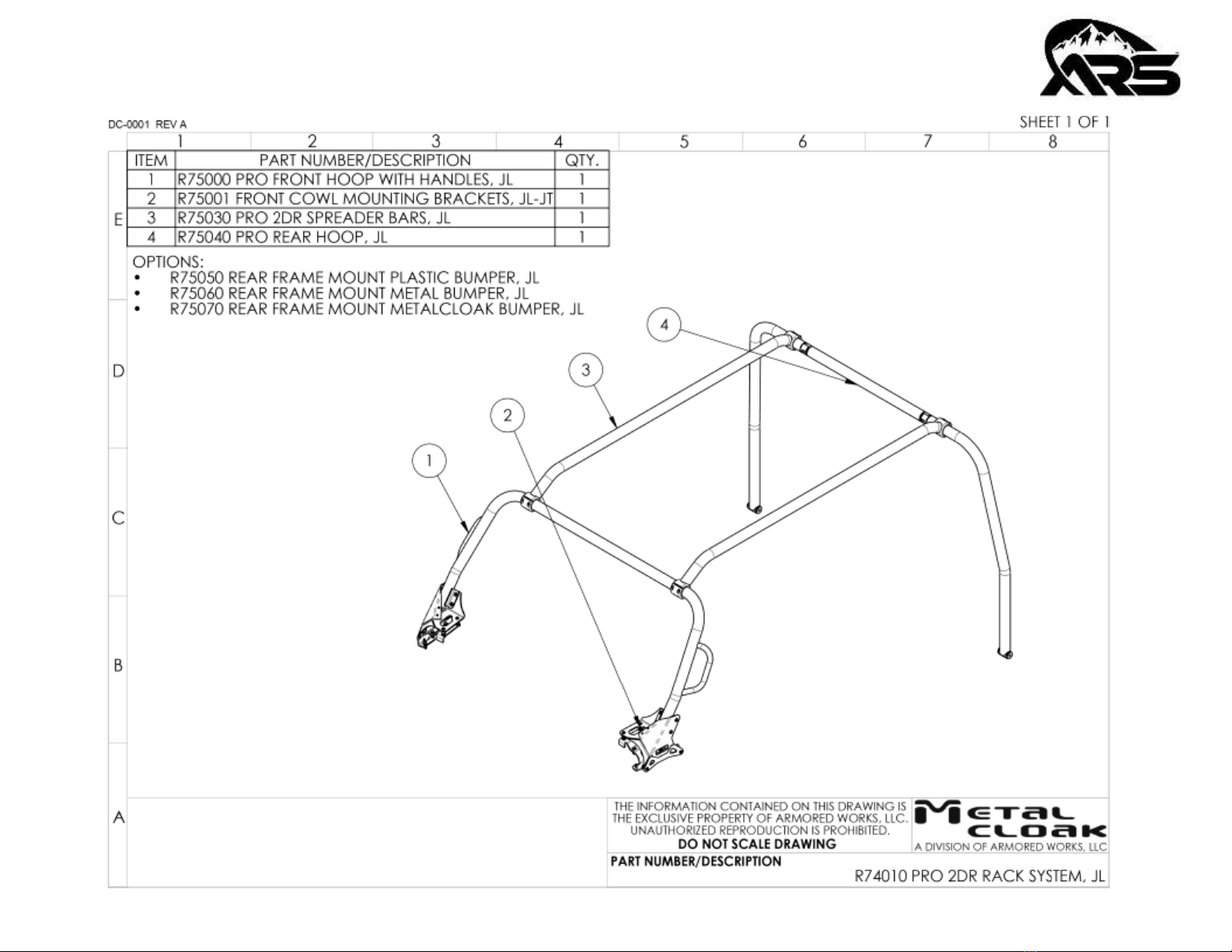
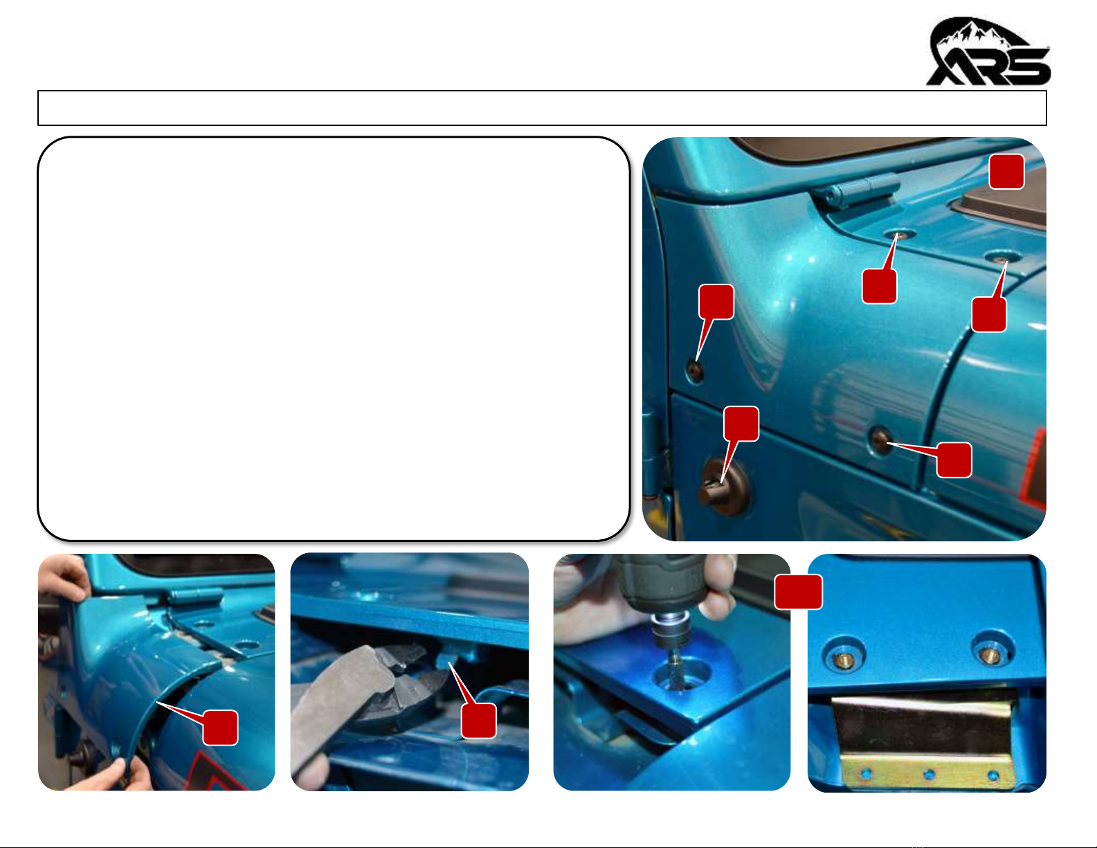
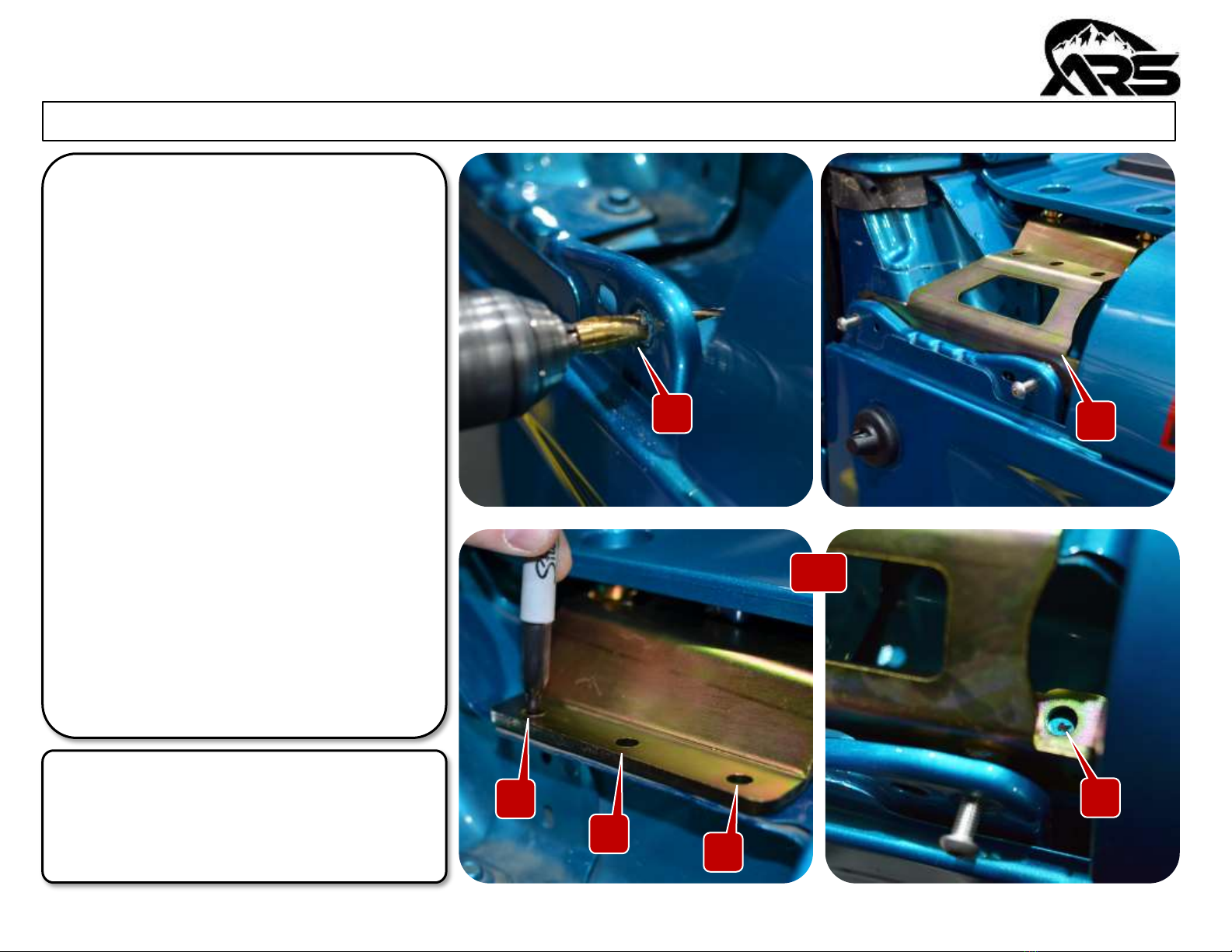
PRODUCT: JL Pro Rack System, MetalCloak Bumper
The ARS experience includes the ease of installation of our products. We design for most contingencies, but installation
may be different based on different Jeep condition, configuration and/or year.
We are continually trying to improve our products and instructions –please help us by providing feedback and pictures if
you find any part of the instructions that do not match your Jeep or are not easily understandable.
If you have any difficulties at all, please give us a call. Thank you and enjoy your ARS Products!
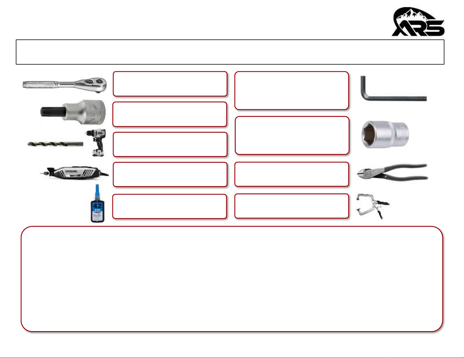
IMPORTANT NOTE: We use Stainless Steel Hardware where possible. Therefore, a tube of Silver Anti-seize is provided and
should be used on all bolts—only a small amount is needed.
WARRANTY INFORMATION: This article is sold without warranty expressed or implied. No warranty or representation is made as to
this products ability to protect the user from injury or death. The user assumes that risk. The effectiveness, warranty and longevity of
this equipment are directly related to the way it is INSTALLED, USED and/or MAINTAINED. THE USER ASSUMES ALL RISK. By
purchasing this product and opening the packaging, purchasers expressly acknowledge, understand and agree that they take, select
and purchase these ARS products from Armored Works, LLC, its affiliates and distributors and agents as is and with all faults. The
entire risk as to the quality and performance of these ARS products is with the purchaser. Working on your vehicle can be a dangerous
activity. If you are unsure of what you are doing, please leave mechanical or safety critical work to a skilled mechanic. We take no
responsibility for the incorrect use and/or installation of ARS products.
READ INSTRUCTIONS IN FULL BEFORE INSTALLATION.
QUESTIONS? CALL 916-760-4575 M-F 7:00 AM –5:00 PM PST
REV: D | 09-22-2023 | R74010
R74000 | Rev D | 09/22/2023| Copyright 2011 Armored Works, LLC Page 2 of 23
Section 1: Tools & Notes on Installation
Tools Required: This list is the recommended tools for ease of installation. Other versions of the same tool can be used. For
example, Allen Wrenches instead of Allen Drive Sockets.
HOW TO USE THIS GUIDE: The installation guide contains ALL steps for installation. Please read and follow the instructions
in order of each page top to bottom and left to right.
Jeep Model: Instructions may apply to multiple Jeep models but are labeled separately where appropriate (i.e. TJ vs. LJ).
Options: Because of the number of component options we offer, these instructions may contain steps that will not match
your configuration. You can skip these steps.
Images: Pictures are provided, and parts are labeled throughout the instructions. Each text box contains guidance based
on the pictures next to it. The text will refer to alphabetical labels (A, B, etc.) found in the images.
Installation Notes: Terms may be used in the body of the instructions that you may not be familiar with, if you have any
questions feel free to contact us at the number below, or email techhelp@metalcloak.com
QUESTIONS: Any questions or comments about the instructions? Call us at 916-760-4575 M-F 7:00 AM –5:00 PM PST.
5mm Allen 7/32” Allen
3/8” Allen 5/16” Allen
1/4” Allen
Socket Wrench
Cutters
Dremel & Cut-Off Wheel
1/2” Socket 9/16” Socket
3/4” Socket 9/16” Wrench
1/2” Wrench 11/16” Wrench
T40 Torx Socket
13/32” Bit 17/32” Bit
5/16 Bit 3/8” Bit
Blue Lock Tight Clamps
R74000 | Rev D | 09/22/2023| Copyright 2011 Armored Works, LLC Page 3 of 23
Section 2: Product Components
R74000 | Rev D | 09/22/2023| Copyright 2011 Armored Works, LLC Page 4 of 23
Section 2: Product Components
R74000 | Rev D | 09/22/2023| Copyright 2011 Armored Works, LLC Page 5 of 23
Section 2: Product Components
R74000 | Rev D | 09/22/2023| Copyright 2011 Armored Works, LLC Page 6 of 23
Section 2: Product Components
R74000 | Rev D | 09/22/2023| Copyright 2011 Armored Works, LLC Page 7 of 23
R74000 | Rev D | 09/22/2023| Copyright 2011 Armored Works, LLC Page 8 of 23
Section 2: Product Components
D
Section 3: Installation Instructions
Step 1: Front Hoop Bracket Installation
A. Remove antenna.
B. Using a T40 torx wrench remove the four stock torx bolts from the
side panel and hood cowl.
C. Remove the cowl cover.
D. Using cutters remove the plastic tab underneath the hood cowl.
E. Mask area around holes and use a dremel enlarge the T40 torx
holes on the hood cowl making sure they are large enough to fit
the upper bracket’s 1/2” standoffs. Do NOT use a drill to open the
holes.
B
1
4
23
C
E
A
R74000 | Rev D | 09/22/2023| Copyright 2011 Armored Works, LLC Page 9 of 23
F
Section 3: Installation Instructions
Step 1: Front Hoop Bracket Installation
F. Enlarge the two outer flange stock
bolt holes to 13/32”.
G. Re-install both parts of the pier
plates temporarily and hold in place
with 2 of the stainless- steel allen-
head bolts
H. Mark the (3) upper bracket holes and
the (1) lower rivet nut hole for
drilling
I. Remove stainless bolts and both
parts of the pier plate (upper and
side bracket).
Note: The side bracket bolt hole that
requires drilling on the passenger side
should align with a pre-existing hole that
will need to be expanded to 17/32”.
I
123
G
4
R74000 | Rev D | 09/22/2023| Copyright 2011 Armored Works, LLC Page 10 of 23
Section 3: Installation Instructions
Step 1: Front Hoop Bracket Installation
J. Center punch and drill a pilot hole
on the three upper bracket
marked locations and step up to a
5/16” drill bit.
K. Center punch and drill a pilot hole
on the one side bracket marked
location and step up to a 17/32”
drill bit. We recommend opening
the hood to gain better access to
the marked location.
L. Paint any exposed metal to
prevent rusting.
M. Using the provided installation
tool install the rivet nut into the
17/32” hole. Use a 9/16” socket
and 11/16” wrench for the
installation tool.
J
K
L
M
Note: The passenger side has two
layers of steel that must be drilled
through.
R74000 | Rev D | 09/22/2023| Copyright 2011 Armored Works, LLC Page 11 of 23
Section 3: Installation Instructions
Step 1: Front Hoop Bracket Installation
N. Using a clamp hold the side panel securely
to help prevent movement when cutting.
Note: The marked locations are the parts that
will need to be removed from the side panel.
Front
Note
Note
Back
N
R74000 | Rev D | 09/22/2023| Copyright 2011 Armored Works, LLC Page 12 of 23
Section 3: Installation Instructions
Step 1: Front Hoop Bracket Installation
O. Using the cut off wheel cut the notches on the front of the plastic side panel. The notches need to be wide enough to fit
around the bracket standoffs (approx. 1/2” Wide).
P. Using a cut off wheel cut off the plastic standoffs on the back of the side panel.
Q. Using a cut off wheel cut off the previously marked center bracket.
P
NO Q
R74000 | Rev D | 09/22/2023| Copyright 2011 Armored Works, LLC Page 13 of 23
Section 3: Installation Instructions
Step 1: Front Hoop Bracket Installation
R. Install the upper and side brackets. The side bracket sits on top of the upper
bracket.
S. Place a spacer washer between each of the three holes of the two brackets.
T. Loosely install the provided bolts, washers and nuts into the three bolt
holes. (There are nine total washers: one washer on top, one as a spacer, one
on the bottom).
U. Install two of the provided allen bolts into the drilled-out stock locations to
hold the side bracket into place before tightening the hex head bolts.
V. Install the provided bolt and split washer into the rivet nut.
R
S T
V
U
R74000 | Rev D | 09/22/2023| Copyright 2011 Armored Works, LLC Page 14 of 23
Section 3: Installation Instructions
Step 2: Front Hoop Mounting Base Installation
W. Place the larger provided spacers into the top T40 bolt locations.
X. Loosely install the hoop mounting base into the top spacers using the
provided longer allen bolts and washers. Do not fully tighten.
Y. Place the provided smaller spacers into the stock T40 bolt locations.
Z. Loosely install the mounting base into the side spacers using the provided
longer allen bolts and washers. Do not fully tighten.
X
Note: ARS highly recommends using blue lock tight on the four allen head bolts
when installing the front hoop mounting base.
W
X
Y
CCZ
R74000 | Rev D | 09/22/2023| Copyright 2011 Armored Works, LLC Page 15 of 23
Section 3: Installation Instructions
Step 3: Front Hoop Installation
AA. Install the finishing caps into the front
hoop.
BB. Using the provided allen head bolts (use
anti-seize) attach the hoop to the
mounting brackets.
CC. On the passenger side insert the antenna
into the provided antenna clamp and
secure to the mounting bracket using the
provided hoop allen bolt. Tighten with a
7/32” allen wrench.
DD. Using a 5mm allen wrench tighten the 4
allen bolts. Repeat on other side.
Z
Note
AA CC
BB
BB
BB
BB
DD
Note: ARS recommends having a second pair of hands help install the
front hoop.
R74000 | Rev D | 09/22/2023| Copyright 2011 Armored Works, LLC Page 16 of 23
R74000 | Rev D | 09/22/2023| Copyright 2011 Armored Works, LLC Page 17 of 23
Section 3: Installation Instructions
Step 4: Rear Hoop Preparation
EE. Install the bushing ends into the end of the rear hoop.
FF. Install the bushing sleeve into the rear hoop bushing ends.
GG. Using a 3/8” allen socket or wrench install the cross bar to the hoop ends.
EE
FF GG
R74000 | Rev D | 09/22/2023| Copyright 2011 Armored Works, LLC Page 18 of 23
Section 3: Installation Instructions
Step 4: Rear Hoop Preparation
HH. Place the spreader bars with the engineered bend facing
the front hoop.
II. Install the spreader bar clamp ends to the front hoop using
the provided allen head bolts. DO NOT FULLY TIGHTEN.
JJ. ARS recommends having a second person help install the
spreader bar clamps to the rear hoop using the provided
allen head bolts. DO NOT FULLY TIGHTEN.
HH
II
II
R74000 | Rev D | 09/22/2023| Copyright 2011 Armored Works, LLC Page 19 of 23
Section 3: Installation Instructions
Step 4: Rear Hoop Preparation
Note: When installing the rear hoop make sure the rear hoop is evenly spaced from the Jeep tub, use a square to make sure
the rear hoop is straight vertically, and make sure there is clearance for the gas cap to open and close.
1 2 3
R74000 | Rev D | 09/22/2023| Copyright 2011 Armored Works, LLC Page 20 of 23
Section 3: Installation Instructions
Step 5: Rear Hoop Mounting Brackets (MetalCloak Bumper)
KK. Once the rear hoop has been aligned mark the rear hoop foot holes for
preparation for drilling.
LL. Using a 9/16” socket remove the rear hoop mounting brackets from the
hoop.
MM.Using a 5/16” allen wrench remove the bumper end cap allen head bolts.
NN. Using a 3/4” socket remove the two hex head bolts on the underside of the
bumper end caps.
KK
LL MM
NN

Other ARS Automobile Accessories manuals

ARS JL Sky Top User manual

ARS

ARS JL Sky Top User manual

ARS R74020 User manual

ARS

ARS R74020 User manual

ARS REVERSE SMART User manual

ARS

ARS REVERSE SMART User manual

Popular Automobile Accessories manuals by other brands

Fiamma MOTOR KIT PLUS F80s Installation and usage instructions

Fiamma

Fiamma MOTOR KIT PLUS F80s Installation and usage instructions

Metra Electronics 99-5600 installation instructions

Metra Electronics

Metra Electronics 99-5600 installation instructions

Bestop Duster 90034 installation instructions

Bestop

Bestop Duster 90034 installation instructions

Parrot MKi9100 user guide

Parrot

Parrot MKi9100 user guide

Alogic CRCA165C1 quick start guide

Alogic

Alogic CRCA165C1 quick start guide

GReddy Type-RS BRS-HGC20 instruction manual

GReddy

GReddy Type-RS BRS-HGC20 instruction manual

ECS Electronics TO-295-07U Fitting instructions

ECS Electronics

ECS Electronics TO-295-07U Fitting instructions

Larson Electronics VMP-GMC-SRA-2019-1500 installation manual

Larson Electronics

Larson Electronics VMP-GMC-SRA-2019-1500 installation manual

Connects2 Vision CAM-FT6 user manual

Connects2

Connects2 Vision CAM-FT6 user manual

Brink 6404 Fitting instructions

Brink

Brink 6404 Fitting instructions

GPS Innovations roadscout RST1 installation guide

GPS Innovations

GPS Innovations roadscout RST1 installation guide

Shoreline 4x4 Extreme Series Fitting instructions

Shoreline 4x4

Shoreline 4x4 Extreme Series Fitting instructions

Ultraplast MD19 user manual

Ultraplast

Ultraplast MD19 user manual

Bulldog Security Auto Clamp Fitting instructions

Bulldog Security

Bulldog Security Auto Clamp Fitting instructions

Tesla Model S Roof Rack owner's manual

Tesla

Tesla Model S Roof Rack owner's manual

DEFA 412708 Fitting instructions

DEFA

DEFA 412708 Fitting instructions

Draw tite 24941, 77328, CQT24941 installation instructions

Draw tite

Draw tite 24941, 77328, CQT24941 installation instructions

Metra Electronics 98-9306 installation instructions

Metra Electronics

Metra Electronics 98-9306 installation instructions

manuals.online logo
manuals.online logoBrands
  • About & Mission
  • Contact us
  • Privacy Policy
  • Terms and Conditions

Copyright 2025 Manuals.Online. All Rights Reserved.