Arsin AR1710 Series User manual

Air Compressor Controller Unit
AR1710 Series: Screw Air Controller
User Manual
Version 92.9

AR1710 Series User’s Manual
2
Read this direction for safety first…
Some of the setting, size etc. on this manual could be changed without an advance notice.
Direction for safety
This direction is for using the product correctly so that you could be safe from danger or incident.
Please carefully keep this all direction.
Please use eighth being attached to a dual safety device in case of using for controlling instruments
which could be effective to human life or property(e.g. : Controlling atomic energy, medical
instruments ,cars ,trains ,flights ,burners, amusement instruments or safety machinery).
Please use with panel, there is a possibility getting an electric shock.
Do not inspect or test with connecting power.
Please connect after checking the terminal number when connecting power.
Do not reorganize except mechanic from ARSIN®
Do not use outdoor .It would be a cause making the product life shorter.
When connecting wires, please give a good screw on terminal. There is a possibility causing a fire with
bad connection.
Please use in the proper performance zone. If you don’t there is a possibility making the product life
shorter or, causing a fire accident.
Do not use a load which is exceeded proper value of opening and shutting capacity of a relay contact.
This will cause bad insulation, bad contact and bad connection.
When cleaning, water or liquid including oil or prohibited, only clean with soft and dried cloth.
Do not use in the place where there is inflammability gas, explosiveness gas, moisture a direct ray of
light, radiation, vibration and a shock.
Please prevent from getting a dirt or leftover wire inside of this product.
When connecting a sensor , please connect correctly after checking the polarity.

AR1710 Series User’s Manual
3
1. OUTLINE
AR1710 is based on Micro Processor and the most advanced equipment for controlling electricity
conducting efficient operation of a screw air compressor.AR1710 is a system managing the compressor’s
operation intensively, saving energy through controlling of timing for capacity adjustment, preventative
and maintenance schedule. In the other word,AR1710 conducts the best operation(control)according to
the condition set up and operating circumstance.
High reliability RISC MICOM
240×128 graphic LCD
Max. 30 events of running log storable (Non-volatile)-Easy preventative & maintenance and analysis for
trouble
Automatic calculation and notice function for preventative & maintenance ,consumable parts exchange
information and expected schedule
Automation of economical operation by embedded weekly timer
Unload Pressure: Pressure value under unload operation with closing intake valve on compressor.
Load Pressure: Pressure value under load operation with opening intake valve on compressor.
Auto Stop Delay: Compressor is stopped in case of continuous operation at unload operation during auto
stop delay time.
Stop Delay: Compressor is stopped after unload operation during manual stop delay time.
Start Delay: Delay time when compressor start load operation from starting.

AR1710 Series User’s Manual
4
1) Special advantages
AR1710 is a stable electronic control unit for screw air compressor which can provide users with running
log for integral control and management of the equipments. It adopts the method of digital process by high
efficiency RISC type microprocessor and occupies enough installation space and stability by unifying
module and control module. It provides convenience to let users know a status of operation at once
through display.
1-1) Noise solution
It is inevitable to figure for noise as an industrial controller. The digital input and output signal of AR1710 is
isolated, so it can not be allowed to flow external signal into the main board inside.CPU on main board
mounts HARDWARE WATCHDOG TIMER which can automatically recover from CPU down occurred by noise
per 32 msec., and BROWN-OUT function embedded in CPU inside supervises control power in real-time.
1-2) RISC TYPE MICOM
An assembler instruction in CPU can perform 7.3728Mbps, and logic for controlling written in CPU inside
needs about 1[m sec] based on 1 cycle. In this regard, sampling rate is about 10 times faster than the
existing controllers, so it has less probability of malfunction and more precise control.
1-3) Black Boxes: A recorder of operation status
It is possible for AR1710 to store maximum until 30 events of running log, so it is easy for preventative &
maintenance and Troubleshooting. Additionally, it is possible to verify the operation data at site occurs, so
it is helpful for users to know the reason of trouble and the status of equipment in real-time.
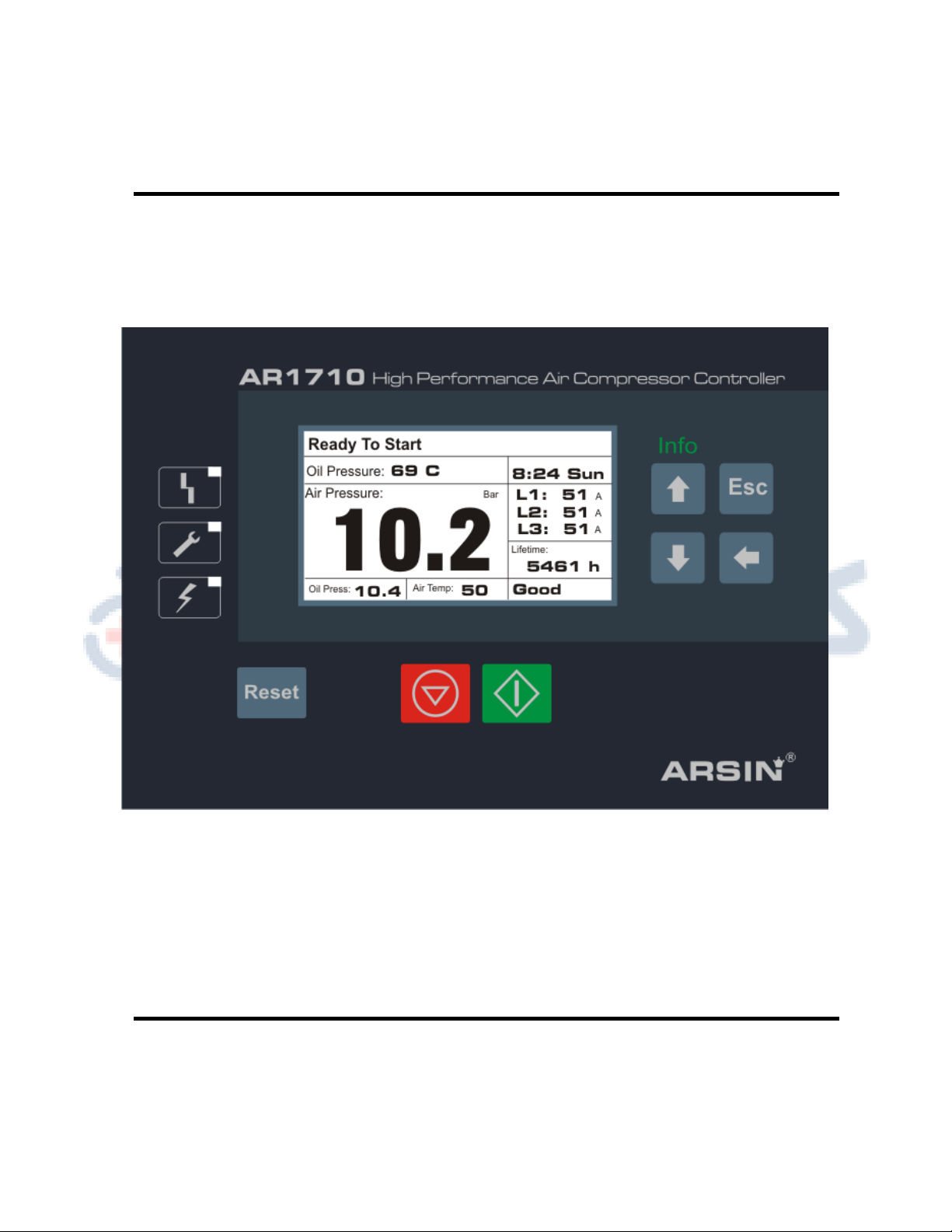
1-4) Display for operation status and/or maintenance (trip computer)
AR1710 has the display function for operation status, delay time and ready time by counting reversely, so
users can recognize the status of compressor at a glance. Also, it has the basic function to notify parts and
oil checking and exchanging schedule by calculating it automatically according to the information of
operation.
1-5) 240×128 graphic LCD (Wide Temperature Range Type: (-50 ~+150°C).Display part of AR1710 adopts
240×128 graphic LCD for user’s easy operation and recognition.
1-6) Minimization
It is possible to minimize compressor by occupying a small space due to unifying design of control part and
display part.
1-7) Scalability
It provides users with RS485 port, MODBUS RTU standard protocol and MMI software and automatic
interface.

AR1710 Series User’s Manual
5
2) Basic specification
2-1) General Specification
Power Conditions
Input Power
AC12V 50/60Hz
Power Consumption
Max 4.0 VA
2-2) CPU & LCD
CPU , LCD
CPU
AT mega 128,16MHz
LCD
240×128 pixel, LED Backlight
2-3) Digital Input &Output
Digital Input
Input Type
Opto -Isolation
Number of Input
8 Points(1 Common)
Signal Power
12V DC
Digital Output
Output Type
Relay Contact
Number of Output
8 Points(1 Common)
Relay Contact Type
250Vac,10Amper
2-4) Analog Input & Output
Analog Input
Temp. Sensor
NTC 2 Points
4~20 mA
2 Points
(Internal Sensor Power 12V)
Correction of
Deviation
Software
Analog Output
--
--
--
--
--
--
2-5) Communication Specifications
Communication
Type
RS485(Half-Duplex) 1 Channel
Modbus RTU
Speed
4800,9600,19200,38400 BPS
(default 9600)
Parity None, Data 8 bit, Stop 1,bit
Distance
Max. 1.2Km
Recommended Cable
BELDEN 9842 or 8761
2-6) Installation Circumstance
Field Conditions
Place
Indoor
Operating Temp.
-10~60°C
Storage Temp.
-30~80°C
Operation Humidity
(No condensation) 5~95%

AR1710 Series User’s Manual
6
2. Input / Output Specification
1) Digital Input Signal
Pin
Name
Function
Active state
10
Com
Input Common Terminal
11
Rmt
Remote Input Signal
Remote (close)
12
Rot
Rotation Fault Signal
Alarm(close)
13
Motor
Motor Bimetal Fault Signal
Alarm(close)
14
Fan
Fan Bimetal Fault Signal
Alarm(close)
15
PSW
Pressure Switch Signal
Alarm(close)
16
EMS
Emergency Stop Signal
Alarm(close)
17
TSW
Thermo Switch Signal(Motor)
Alarm(close)
18
Oil
Oil Level Sensor Signal
Alarm(close)
2) Power Output Signal
Pin
Name
Function
Active state
33
Com
Power Common Terminal
34
MF3
Multi Function Output # 3
Output(NO)
35
MF2
Multi Function Output # 2
Output(NO)
36
MF1
Multi Function Output # 1
Output(NO)
37
Fan
Fan Motor Output
Output(NO)
38
Valve
Solenoid Valve Output
Output(NO)
39
Norm
Normal Contactor Output
Output(NO)
40
Rectangular Contactor Output
Output(NO)
41
Y
Star Contactor Output
Output(NO)
3) Analog Input Signal
Pin
Name
Function
Type
Range
19
Temp
Oil Temperature Sensor (1)
Pt1000
-50~150 C
20
Temp
Oil Temperature Sensor (2)
Pt1000
-50~150 C
21
Temp
Air Temperature Sensor (1)
Pt1000
-50~150 C
22
Temp
Air Temperature Sensor (2)
Pt1000
-50~150 C
23
+12V
Oil Pressure Transmitter (+)
4~20mA
Settable
24
Out
Oil Pressure Transmitter (-)
4~20mA
Settable
25
+12V
Air Pressure Transmitter (+)
4~20mA
Settable
26
Out
Air Pressure Transmitter (-)
4~20mA
Settable

AR1710 Series User’s Manual
7
BELDEN 9842 standard cable is recommendable
6) Power Supply Inputs
Pin
Name
Function
6,7
Auxiliary Supply
AC12V
8,9
Main Supply
AC12V

AR1710 Series User’s Manual
8
7) Current measurement
Pin
Name
Function
Active state
27
CT1
Current Sampling L1
Loop circuit
28
CT1
Current Sampling L1
Loop circuit
29
CT2
Current Sampling L2
Loop circuit
30
CT2
Current Sampling L2
Loop circuit
31
CT3
Current Sampling L3
Loop circuit
32
CT3
Current Sampling L3
Loop circuit
100/5….500/5 Ratio

AR1710 Series User’s Manual
9
Constitution
1) Dimensions and panel Cut-Out Information front view:
2) Back view:

AR1710 Series User’s Manual
10
1-1) Basic Constitution
Display part specification: 240×128 Graphic LCD
1-2) Operation part
Reset: Reset when trip occurred
1-3) Program setup part
Enter switch: selection of setup program or value
Downward Switch: Moving down to setup program or value
Upward switch: Moving up to setup program or value
Menu switch: Opening menu for setup
Escape switch: Returning to the previous menu or initial screen
2) Display for Operation Status

AR1710 Series User’s Manual
11
2) Operation Button Function
Start
Select Start
The equipment starts when pushing start button.
Stop
Select Stop
The equipment stops when pushing stop button.
Reset
Reset when trip
The trip reset automatically doesn’t need to push
reset button.
Enter
Entering to programming / enter to new menu
Up/Down
Upward(Increase)and/or Download (Decrease)
Escape
Exit from current menu
3) Status display lamp
RED
Error occurred in system
Yellow
It’s the time for system to be serviced or warning in progress
GREEN
Power supply applied
4) Display Explanation
L
Operating Mode : Local
R
Operating Mode : Remote
N
Operating Mode: Network
W
Schedule Program Enabled
GOOD
Normal Operation
Mainten
Need to be Serviced
S_DOWN
Shut down Trip
FAULT
Fault Occurred
Inhibit
Unable to be run by an inhibition cause

AR1710 Series User’s Manual
12
5. Menu Constitution
1) Main Screen Constitution Type
OPERATION
RUNNING LOG
SCHEDULE
MAINTENANCE
SHUTDOEN
WARN MODE
START INHIBIT
COMPRESSOR
STATUS
CONFIGURATION
CONTRAST
MOTOR SETTING
SYSTEM DATE-TIME
TEST MODE
Delivery Air Temp : 150 C
Delivery Pressure : 0.0Bar
Oil Pressure : 0.0C
Oil Temperature : 150C
Differential Press. : 0.0Bar
Total Run Hours : 00379h
ST AT U S

AR1710 Series User’s Manual
13
STATUS
RUNNING LOG
SCHEDULE
MAINTENANCE
SHUTDOEN
WARN MODE
START INHIBIT
COMPRESSOR
0.2 Bar
Load Pressure : 6.0 Bar
Auto Stop Delay : 10 Min
Stop Delay : 05 Sec
Start Delay : 05 Sec
Drain Time[On] : 05 Sec
Drain Time[Off] : 05 Min
Unload Pressure :
STATUS
OPERATION
SCHEDULE
MAINTENANCE
SHUTDOEN
WARN MODE
START INHIBIT
COMPRESSOR
RUNNING LOG
#00 1391/01/07 08:05
#011391/02/0812:051```````
Emergency Stop .p
#021301/02/07 21:05
Emergency Stop .p
#031301/03/07 20:15
Main Motor Fault .p
Oil High Pressure
OPERATION
RUNNING LOG

AR1710 Series User’s Manual
14
STATUS
OPERATION
RUNNING LOG
MAINTENANCE
SHUTDOEN
WARN MODE
START INHIBIT
COMPRESSOR
SCHEDULE
SCHDULE .
08:00
Sunday Off : 17:00
Monday On : 08:00
Monday Off : 17:00
Tuesday On : 08:00
Tuesday Off : 17:00
Wednesday On : 08:00
Wednesday Off : 17:00
Sunday On :
17:00 : 08:00
Thursday Off : 17:00
Friday On : 08:00
Friday Off : 17:00
Saturday On : 08:00
Saturday Off : 17:00
Thursday On:
08:00

AR1710 Series User’s Manual
15
.
.
.
.
.
.
STATUS
OPERATION
RUNNING LOG
SCHEDULE
SHUTDOEN
WARN MODE
START INHIBIT
COMPRESSOR
MAINTENANCE
MAINTENANCE .
: 1000h
Suction Filter : 1000h
Oil Filter : 1000h
Lub. Oil Filter : 1000h
Cooler Cleaning : 1000h
Overhaul : 5000h
Dust Filter :

AR1710 Series User’s Manual
16
1)Menu construction
STATUS
SCHEDULE
OPERATION
RUNNING LOG
00: Delivery Air Temp.
01: Delivery Press.
03:Oil Pressure.
04: Oil Temperature.
05: Differential Pres.
06:Total Run Hours
00: Unload Pressure
01: Load Pressure
02: Auto Stop Delay
03: Stop Delay
04: Start Delay
05: Drain Time [On]
06: Drain Interval [Off]
07: Cooling Fan Run
08: Cooling Fan Stop
09: LCD Backlight Mode
00: Sun: Start ~ Stop
01: Mon: Start ~ Stop
02: Tue: Start ~ Stop
03: Wed: Start ~ Stop
04: Thu Start ~ Stop
05: Fri: Start ~ Stop
06: Sat: Start ~ Stop
00: Event #1
01: Event #2
02: Event #3
.
.|
31: Event #32
MAITENANCE
ALARM MODE
SHOUTDOWN
START INHIBIT
00: Dust Filter
01: Suction Filter
02: Oil Filter
03: Lub. Oil Change
04: Cooler Cleaning
05: Overhaul
00:Delivery Temp. High
01:Delivery Press. High
02:Oil Rec. Temp. High
03:Oil Rec. Press. High
04:Diff-Pressure High
00:Delivery Temp.
High
01:Delivery Press.
High
02:Oil Rec. Temp.
High
03:Oil Rec. Press. High
04:Diff-Pressure High
00:Delivery Temp.
Low
01:Delivery Press.
High

AR1710 Series User’s Manual
17
COMPRESSOR
00: Y-Delta Transfer
Time
01: Load Delay Time
02: Reload Delay Time
03: Diff-Press. Detect
Delay
04: Load Command
Mode
05: Starting Command
Mode
06: Power Return
Restart
07: Network ID
08: Network BPS
VSD MODE*
00:VSD Control Mode
01:Maximum Speed
02:Minimum Speed
03:Optimum Speed
04:Unloaded Speed
05:Speed Command (Hz)
06: Speed Command
(mA)
07:Proportional Band(P)
08:Integral Time(I)
09:Dead Band
10:Jerk Control Ratio
11:Max.Inverter RPM
12:Max.Inverter
Frequency
TEST MODE
00: Master Password
Setup
01: Trip/Alarm
HistoryDelete
02: Operation History
Delete
03: Reverse Phase Signal
04: Oil Rec. P-Sensor Use
05:Oil Rec. T-Sensor Use
06:Deliovery Press.
Correction
07:Oil Rec. press.
Correction
09:Delivery Temp.
Cporrection
10:Oil Rec. Temp.
Correction
11:Min. Delivery Press.
12:Max. Delivery Press
13:Min Oil Rec. Press
14:Max. Oil Rec. Press.
15:Multi Function 1
16:Multi Function 2
17:Multi Function 3
CONFIGURATION
00:Manual Test Mode
01:Multi Function N1
02: Multi Function N2
03: Multi Function N3
04: Multi Function N4
05:Main Motor MAIN
06:Main Motor STAR
07:Main Motor DELTA
08:Load Solenoid
Valve
09:Invertal Control*
10:Delivery Press.
Retrans*
DIAGNOSTIC
00:SELF TEST
01:B1 Input
02: B2 Input
03:B3 Input
04:B4 Input
06: B3 4mA
07: B3 20 mA
08:B4 4mA
09: B4 20mA
10:Y1 4mA
11:Y1 20mA
12:Y2 4mA
13:Y2 20mA
16:ADC F/T
17:DAC F/T

AR1710 Series User’s Manual
18
10-1) Trip Message
Description
Detect condition
1
System Fault
In case of unexpected change of the value of parameter
2
Emergency Stop
[Digital Signal Input : Emergency Stop] : ON
[Digital Signal Input : Emergency Stop] : OFF
3
Fan Motor O.L.
[Digital Signal Input : Fan Motor O.L] : ON
[Digital Signal Input : Fan Motor O.L] : OFF
4
Delivery
Pressure High
Delivery Pressure ≥ [Shutdown: Delivery Pressure High]
Delivery Pressure < [Shutdown: Delivery Pressure High] - 0.5bar
5
Delivery
Temp. High
Delivery Temp. ≥ [Shutdown: Delivery Temp. High]
Delivery Temp. < [Shutdown: Delivery Temp. High] - 5℃
6
Oil Rec.
Pressure High
Oil Rec. Pressure ≥ [Shutdown: Oil Rec. Pressure High]
Oil Rec. Pressure < [Shutdown: Oil Rec. Pressure High] –0.5bar
7
Oil Rec.
Temp. High
Oil Rec. Temperature ≥ [Shutdown: Oil Rec. Temp. High]
Oil Rec. Temperature < [Shutdown: Oil Rec. Temp. High] - 5℃
8
Diff-Pressure
High
(Oil Rec. Pressure–Delivery Pressure) ≥
[Alarm Mode: Diff-Press. High] & Delivery Air Temperature > 50℃
(Oil Rec. Pressure–Delivery Pressure.) < [Alarm Mode: Diff-Press.
High] - 0.1bar
9
Brow down Time
Over
Oil Rec. Pressure > [Start Inhibit : Oil Rec. Pressure High] in case of exceeding
of [Operation :
Blow down Delay Time] during brow down check sequence
10
Delivery
P-Sensor
In case of occurrence of error on delivery Pressure sensor (disconnection)
In case of normal condition of delivery Pressure sensor
11
Delivery
T-Sensor
In case of occurrence of error on delivery temp. sensor (disconnection )
In case of normal condition of delivery temp. sensor
12
Oil Rec.
P-Sensor Fault
In case of occurrence of error on oil rec. pressure sensor (disconnection )
In case of normal condition of oil rec. pressure sensor
13
Oil Rec.
T-Sensor Fault
In case of occurrence of error on oil rec. temperature sensor
(disconnection)
In case of normal condition of oil rec. temperature sensor
Sensing
Reset
Reset
Sensing
Sensing
Reset
Sensing
Reset
Sensing
Reset
Sensing
Reset
Sensing
Reset
Sensing
Reset
Sensing
Reset
SensingReset
Sensing
Reset
Sensing
Reset

AR1710 Series User’s Manual
19
※Fault message occurred is reset by pushing [Reset] button after solving related reason.
10-2) Alarm Message
Item
Description
Detect condition
1
Oil Filter
High
[Digital Signal Input : Oil Filter High] : ON
[Digital Signal Input : Oil Filter High] : OFF
2
Air Filter
HighDP
[Digital Signal Input : Air Filter High DP] : ON
[Digital Signal Input : Air Filter High DP] : OFF
3
Oil Rec.
Press. High
[Digital Signal Input : Oil Reclaimer High Press.] : ON
[Digital Signal Input : Oil Reclaimer High Press.] : OFF
4
Delivery
Pressure
High
Delivery Pressure ≥ [Alarm Mode : Delivery Pressure High]
Delivery Pressure < [Alarm Mode : Delivery Pressure High]-0.5bar
5
Delivery
Temp. High
Delivery Temp. ≥ [Alarm Mode : Delivery Temp. High]
Delivery Temp. < [Alarm Mode : Delivery Temp. High]-5℃
6
Oil Rec.
Press. High
Oil Rec. Pressure ≥ [Alarm Mode : Oil Rec. Pressure High]
Oil Rec. Pressure < [Alarm Mode : Oil Rec. Pressure High]- 0.5bar
7
Oil Rec.
Temp. High
Oil Rec. Temperature ≥ [Alarm Mode : Oil Rec. Temperature High]
Oil Rec. Temperature < [Alarm Mode : Oil Rec. Temperature High]-5℃
8
Diff-
Pressure
High
(Oil Rec. Pressure –Delivery Pressure) ≥
[Alarm Mode: Diff- Pressure High] & Delivery Air Temp. >50℃
(Oil Rec. Press. –Delivery Press.) < [Alarm Mode: Diff- Pressure High]-0.1bar
9
RTC Stop
Alarm
RTC is not working, (Sensible during scheduled operation)
RTC is in ordinary operation, (necessary to reset the time)
※Occurred alarm message is automatically reset in case of reset condition
Sensing
Reset
Sensing
Reset
Sensing
Reset
Sensing
Reset
Sensing
Reset
Sensing
Reset
Sensing
Reset
Sensing
Reset
Sensing
Reset

AR1710 Series User’s Manual
20
6. Wiring Diagram
Table of contents
Other Arsin Control Unit manuals
Popular Control Unit manuals by other brands

TechNexion
TechNexion FLEX-IMX8M-Mini product manual

KEYBOARDPARTNER
KEYBOARDPARTNER HX3.5 WiFi Module installation guide

Belden
Belden DCX XCONNECT SPOOL quick start guide

RectorSeal
RectorSeal Clean Check Maintenance Guide

Xblue Networks
Xblue Networks X16 Quick reference card

Hours
Hours JOG DIAL user manual