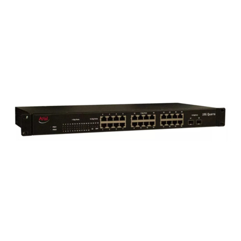
Artel INFINITYLINK ILC205 Operating instructions

WWW.ARTEL.COM
MAnuAL
9 Port Gigabit Ethernet Switch with VLAN
Installation and Operations Manual
INFINITYLINK ILC205

ii ILC205 Function Module Installation and Operations Manual

ILC205 Function Module Installation and Operations Manual iii
Document Number: AR200-006105-10_A
Released: December, 2016
ILC205 Function Module
9 Port Gigabit Ethernet Switch withVLAN
Installation and Operations Manual

iv ILC205 Function Module Installation and Operations Manual

ILC205 Function Module Installation and Operations Manual v
COPYRIGHT
This manual is produced and copyrighted by Artel Video Systems Corporation. Any use or reproduction of the
contents of this manual without the prior written consent of Artel Video Systems Corporation is strictly
prohibited.
NOTICE
All title and copyrights to this document are owned by Artel Video Systems Corporation. No part of the
contents of this document may be reproduced or transmitted in any form or by any means without the written
permission of Artel Video Systems Corporation.
Artel Video Systems Corporation shall not be liable for errors contained herein. ArtelVideo Systems
Corporation shall not be liable for any damages whatsoever, including, without limitation, damages for loss of
business prots, business interruption, loss of business information, or other pecuniary loss arising out of the
use of this documentation even if Artel Video Systems Corporation has been made aware of the possibility of
such damages.
Information contained in this document is subject to change without notice. While every eort is made to
ensure that the information is accurate as of the publication date, users are reminded to update their use of
this document with documents published by Artel Video Systems Corporation subsequent to this date.
Updates may be available at www.artel.com or by contacting Artel Video Systems Corporation.
Third-party product information is for informational purposes only, and constitutes neither an endorsement
nor a recommendation. Artel Video Systems Corporation assumes no responsibility with regard to the
performance of the third-party products.
Copyright © 2016 by ArtelVideo Systems Corporation
ALL RIGHTS RESERVED
Printed in U.S.A.
Artel Video Systems Corporation
5B Lyberty Way
Westford, MA 01886
(978) 263-5775
www.artel.com

vi ILC205 Function Module Installation and Operations Manual
Revision history for the ILC205 Function Module Installation and Operations Manual.
Table 0-1. Manual Revision History
Revision History
Revision Document Number Date Reason for Change
AAR200-006105-10_A December, 2016 Initial release.

ILC205 Function Module Installation and Operations Manual vii
Table of Contents
About This Manual
Audience........................................................................................................................................... ix
Related Documentation ................................................................................................................ ix
Symbols and Conventions.............................................................................................................. x
Artel Customer Service ................................................................................................................... x
ILC205 Function Modules
Information About the ILC205 Modules ......................................................................................1
ILC205 Modules Functional Descriptions ....................................................................................2
Overview of the ILC205 Modules ..................................................................................................3
Installing the ILC205 Module.........................................................................................................5
Cabling the ILC205 Modules ..........................................................................................................6
Conguring the Module with InnityLink Manager..................................................................7
Monitoring ILC205 Operations....................................................................................................13
Monitoring Using the Module Panel LEDs ......................................................................................13
Understanding the Front Panel Status LEDs..........................................................................13
Understanding the Rear Panel Status LEDs............................................................................14
Monitoring Using InnityLink Manager........................................................................................... 15
Removing an SFP or Module ........................................................................................................17
Removing an SFP .....................................................................................................................................17
Removing a Module................................................................................................................................17

viii ILC205 Function Module Installation and Operations Manual

ILC205 Function Module Installation and Operations Manual ix
About This Manual
This manual provides instructions for installing, conguring, and operating the ILC205 function modules.
Audience
This manual is intended for the following trained and qualied service personnel who are responsible for
installing and operating the ILC205 module:
• System installer
• Hardware technician
• System operator
Related Documentation
The following documentation contains material related to the ILC205 function modules:
Document Provides . . .
ILC205 Data Sheet Product operating and environmental specications, and regulatory
conformance information.
ILC205 Quick Start Guide Product conguration information and descriptions of the front and
rear panel status LED operations.
InnityLink IL6000 Chassis Manual Overview and installation instructions for the InnityLink media
transport platform chassis options, including the following:
• IL6000 chassis—Installation of this 4-slot chassis, power supplies,
and function modules.
InnityLink IL6000 Chassis Data Sheet Overview of the InnityLink media transport platform chassis options.
InnityLink Manager Setup and Operations
Manual
Overview and operating instructions for the InnityLink Manager
element management system.

xILC205 Function Module Installation and Operations Manual
Symbols and Conventions
This manual uses the following symbols and conventions.
Caution
A caution means that a specic action you take or fail to take could cause harm to the equipment or
to the data transmission.
Warning
A warning describes an action you take or fail to take that could result in death, serious physical injury, or
destruction of property.
Note: Important related information, reminders, and recommendations.
Italics—used for emphasis, for indicating the rst occurrence of a new term, and for book titles
1. Numbered list—where the order of the items is important
• Bulleted list—where the items are of equal importance and their order is unimportant
Artel Customer Service
In the US call (800) 225-0228, then select 1 for technical support.
Outside the US call (978) 263-5775, then select 1 for technical support.
When requesting assistance, please be ready to provide the following information:
• Your name and telephone number
• Product model and serial number
• Brief description of the problem
• List of symptoms
• Steps you have already taken to try to resolve the problem
If the product is damaged
If any portion of the unit is damaged, forward an immediate request to the delivering carrier to perform an
inspection of the product and to prepare a damage report. Save the container and all packing materials until
the contents are veried.
Concurrently, report the nature and extent of the damage to Artel Customer Service so that action can be
initiated to either repair or replace the damaged items.
Do not return any items to Artel until you obtain instructions from Customer Service.
Report the problem or deciency to Customer Service along with the model number and serial number. Upon
receipt of this information, Artel will provide service instructions, or a Return Authorization Number and
shipping information.

ILC205 Function Module Installation and Operations Manual 1
Information About the ILC205 Modules
ILC205 Function Modules
Ethernet Aggregators and Optical Transceivers
Information About the ILC205 Modules
Note: The installation and operation of the ILC205 module is similar regardless of the Artel chassis
model that hosts the module.This manual points out any dierences where needed.
This manual introduces the ILC205 function module and includes information for installing and conguring
them. The ILC205 module aggregates local IP trac and video-over-IP trac from other Artel host chassis
function and management modules, requiring fewer wired or optical connections to external networks.
Additional features include the following:
• Nine-port, layer 2 Ethernet switch.
• Five external 1 gigabit Ethernet (1 GigE) ports as follows:
– Three 10/100/1000 Mb/s RJ45 connectors that support auto-MDIX and negotiation.
– Two small form-factor pluggable (SFP) ports that can provide two bidirectional links between a
pair of ILC205 modules or to an optical Ethernet switch. These ports allow redundant optical inks,
an optical repeater function, or additional copper ports by using RJ45 SFPs.
• Four internal 1GigE ports to the backplane.
• VLAN tagging and trunking capabilities.
You provision and monitor the ILC205 modules as follows:
• Provision and monitor the module remotely using InnityLink Manager running on a chassis power
supply module). For more information, see the InnityLink Manager Setup and Operations Manual.
• Monitor the module locally using the front and rear panel status LEDs.

2ILC205 Function Module Installation and Operations Manual
ILC205 Function Modules
ILC205 Modules Functional Descriptions
This section provides a functional description of the ILC205 module, including Figure 1, which is a functional
block diagram of the module.
Figure 1. ILC205 Module Functional Block Diagram
Electrical/Optical Inputs and Outputs
The ILC205 module uses the following inputs and outputs:
• Three rear panel RJ45 connectors.
• Two rear panel SFP sockets for either of the following:
– Two optical connections
– Two additional RJ45 connections
• Four sets (transmit/receive) of backplane connections for sharing signals with other host chassis
modules.

ILC205 Function Module Installation and Operations Manual 3
Overview of the ILC205 Module
This section provides an overview of the components that make up the ILC205 module.
Figure 2. ILC205 Module Major Components
Table 1. ILC205 Elements
Item Module Element for details, see...
1RJ45 connectors P1, P2, and P3. • Cabling the Data Input RJ45
Connections (page 6)
• Understanding the Rear Panel Status
LEDs (page 14)
2SFP sockets SFP1 and SFP2. • Cabling the SFP Connections (page 6)
• Understanding the Rear Panel Status
LEDs (page 14)
3Rear panel alarm indicator OK LED. Understanding the Rear Panel Status LEDs
(page 14)
123
4 5 6
7
8
10

4ILC205 Function Module Installation and Operations Manual
ILC205 Function Modules
Table 1. ILC205 Elements
Item Module Element for details, see...
4Front panel alarm indicator OK LED. Understanding the Front Panel Status LEDs
(page 13)
5Front panel status LEDs for RJ45 connectors P1, P2, and P3.
6Front panel status LEDs for SFP connectors SFP1 and SFP2.
7Backplane connector that provides power to the module,
allows the module to share signals with other function
modules, and is used for alarm and management signals.
N/A
(Continued)

ILC205 Function Module Installation and Operations Manual 5
Installing the ILC205 Module
The ILC205 module and associated SFPs are hot swappable, enabling you to safely install them while power is
applied to the host chassis. Before you install the module, see the ILC205 data sheet for a detailed description
of the module specications including environmental requirements that you must adhere to when installing
the module.
To install the ILC205 module in the host chassis (see Figure 3), perform the following steps:
1. From the back of the chassis, remove the two screws that secure the blank tray to the unused function
module slot.
Use any available function module slot.
2. Slide the module into the chassis slot using the printed circuit board guide rails on either side of the slot.
3. Push the module in until it is rmly seated into the backplane and ush with the chassis.
4. Tighten the two mounting screws that secure the module to the chassis.
5. Install the Artel-approved SFPs in the module (handle on top as shown in Figure 3).
Push the SFP into the socket located on the right side of the function module until it is rmly seated into
the socket.
6. Insert a blank tray in any unused chassis module slots to maintain proper ventilation.
Figure 3. ILC205 Module and SFP Installation
SFP
(handle on top)
Module
Mounting Screws
(2)

6ILC205 Function Module Installation and Operations Manual
ILC205 Function Modules
Cabling the ILC205 Modules
This section describes how to cable the external connections of the ILC205 module, which can receive external
signals over its RJ45 connectors and SFPs.The SFPs, which can also be used for transmitting external signals,
can be optical (LC connectors) or electrical (RJ45 connectors). The cabling conguration that you use depends
on your application.
Figure 4. ILC205 RJ45 Connectors and SFP Sockets
Cabling the Data Input RJ45 Connections
Use Ethernet cables with RJ45 plugs to connect the module’s RJ45 connectors to the source or destination
devices.
Cabling the SFP Connections
When using optical SFPs, use a single mode ber when connecting to the LC connectors of the SFPs.
To cable the optical connections, perform the following tasks:
1. Remove the SFP safety plug that protects the TX/RX ports.
Cover any unused optical port to keep the port clean.
2. Connect the ber optic cable between the SFP optical connectors on the module and the external source
or destination device.

ILC205 Function Module Installation and Operations Manual 7
Conguring the Module with InnityLink Manager
You congure the ILC205 module operation using the InnityLink Manager element management system and
the module’s conguration page.
Guidelines
You can congure the ILC205 Ethernet module to act as either a simple 802.3 switch or as a 802.3ac
VLAN-aware switch. This conguration setting applies to all ports.With VLAN support enabled, you can
enable double tagging (referred to as QinQ) on a single trunking interface. Double tagging inserts a
second tag, known as the provider tag, that is formed from the EtherType congured and the PVID
associated with the frames ingress port. This feature is intended to be used in conjunction with third-
party provider backbones that isolate each customer’s trac based on unique tags. The inner tag is
copied from the original tagged frame and is called the Customer tag. Untagged trac can not be
transported over a congured QinQ link, but can still pass between other ports on the module if needed.
Another key component of VLANs is the ability to prioritize trac.This can be accomplished by attached
devices that send 802.1Q tagged frames with a tag and priority dened or by conguring the module to
add a default VLAN ID and priority on a port-by-port basis. The modules include four queues that are
mapped to the 802.1Q priorities (see Table 4). The module uses a strict priority scheduling algorithm that
forwards frames only when no higher priority frames are in the queue. Keeping the MGMT VLAN priority
at the highest priority (7) will help maintain your management connectivity over congested links.
Caution
Do not modify the VLAN conguration in such a way as to block your management trac path.
Prerequisites
To congure the ILC205 module, you must access the InnityLink Manager that manages the module. For
details about accessing and setting up InnityLink Manager, see the
InnityLink Manager Setup and Operations Manual.

8ILC205 Function Module Installation and Operations Manual
ILC205 Function Modules
Procedure
To congure the ILC205 module operation, perform the following steps:
1. From a browser window, enter the IP address of the InnityLink Manager that manages the module.
The Home page displays.
2. From the Home page menu bar, click Shelf View.
The Shelf View page displays, which shows the rear chassis panel along with the Installed Modules table.
3. From the Installed Modules table, click the Conguration link associated with the ILC205 listed in the
Module Type column.
The Conguration page displays.
4. From the Physical Layer Conguration panel, congure the module’s physical port connections as
described in the following table.
Table 2. Physical Layer Conguration Parameters
Parameter Setting Description
P1 to P3
(RJ45 connectors
Enable (Check/
Uncheck)
Check the checkbox to enable the port or uncheck it to disable
the port. The default is Enabled.
Rate Limit Select the appropriate port rate limit: 1Gb/s, 100Mb/s,
10Mb/s, or Auto. The default is Auto or auto-MDIX and
auto-negotiation.
Duplex Limit Select the appropriate duplex setting: Full or Half. The default
is Full duplex.
Enable Alarms
(Check/Uncheck)
Check the checkbox to enable the alarm feature. Uncheck the
checkbox to disable the alarm feature. The default is Disabled.
SFP1 and SFP2 Enable Check the checkbox to enable the port or uncheck it to disable
the port. The default is Enabled.
Note: The rate limit for the SFP ports is set to 1Gb and cannot
be modied.
Enable Alarms Check the checkbox to enable the alarm feature. Uncheck the
checkbox to disable the alarm feature. The default is Disabled.
BP1 to BP4
(backplane connections)
Selectable Use the drop-down boxes to select a backplane connection for
Channels A to D. This step sets up a connection between the
selected backplane connection and the rear panel connections.
The connection options that display varies depending on the
module types that the host chassis contains.

ILC205 Function Module Installation and Operations Manual 9
Conguring the Module with InnityLink Manager
5. From the Virtual Layer Conguration panel, congure the virtual layer parameters for each of the
module’s ports as described in the following table.
Table 3. Virtual Layer Conguration Parameters
Parameter Setting Description
Trunk Select Selectable Select a single interface for QinQ trac. If QinQ is not enabled,
then this setting has no aect. Only the selected VLAN
Memberships will be forwarded over the trunk. Use of the PVID
for untagged trac is not allowed.
Select the None option to disable trunking,
VLAN Membership Check/Uncheck
(A to H and MGMT)
Use the A to H checkboxes to specify the port’s VLAN
membership.VLAN membership selections, in conjunction with
the PVID entry, control which frames can egress a particular port
and whether the frames will have a tag added or stripped. When
there are conicting rules pertaining to a specic VID, the
untagged PVID takes priority.
Guidelines
If a port has membership in an enabled VLAN, then trac tagged
with a matching VLAN ID ingresses and the following actions may
occur:
• Tagged trac that ingresses this port may egress any port
that is a tagged member of the VLAN with which the packets
are tagged.This trac will egress tagged.
• Tagged trac that ingresses this port may egress any port
that has a PVID that matches theVLAN ID with which these
packets are tagged.This trac will egress untagged.
• If this trac egresses a port which is both a member of the
VLAN with which these packets are tagged and has PVID
matching that VLAN ID, this trac will egress untagged.
• Untagged trac will be discarded on ingress if this port has a
PVID of 0.

10 ILC205 Function Module Installation and Operations Manual
ILC205 Function Modules
Table 3. Virtual Layer Conguration Parameters
Parameter Setting Description
Untagged
Membership
PVID Specify a port VLAN ID (PVID).The valid range is 0to 4095 where
0signies no PVID assigned.The default is 1.
Guidelines
• If you enter a PVID of 0 and this port is not a member of an
enabled VLAN, then no trac can ingress or egress using this
port.
• Any untagged trac may ingress a port that has a PVID other
than 0 assigned to it.
• Untagged trac that ingresses via this port may egress from
any port with a matching PVID. This trac will egress
untagged.
• Untagged trac that ingresses via this port may also egress
through any port that is a member of an enabled VLAN
whose VLAN ID matches this ports PVID. This trac will
egress tagged.
• Tagged trac may ingress using this port if it is tagged with
a VLAN ID which matches this port’s PVID.
Note: Tagged trac may egress untagged from any port
whose PVID matches this port PVID.This trac may
egress tagged from any port that has a PVID not
matching this port PVID and that is a member of an
enabled VLAN whose VLAN ID matches this port
PVID.
Priority From the drop-down list, select a VLAN priority level of 0to 7(as
dened in 802.1Q) with 7being the highest priority. The default is
0.
Because the internal switch hardware has only four output
queues used to implement QoS (values 0 to 3), two 802.1Q
priority values are mapped to a unique internal QoS queue
priority value as shown in the following table:
Table 4. Priority Mapping
(Continued)
Table of contents
Other Artel Switch manuals