Artemide SKYDRO User manual

I
SKYDRO designed by Ross Lovegrove Apparecchio in CL I IP20
AVVERTENZE
Prima di ogni operazione sull’apparecchio, disinserire la tensione di rete.
Usare esclusivamente le lampadine del tipo epotenza indicati nei dati di targa.
ARTEMIDES.p.a. nonsi assumealcuna responsabilità per prodotti modificati senzaprevia autorizzazione.
ATTENZIONE:Per procedere all’installazione dell’apparecchio in modo corretto sono necessarie almeno
due persone.
Incaso dimontaggio susupporti mobili (es.controsoffitti), verificare attentamente cheglistessiassicurino
adeguato contrasto prima di seguire ipassi descritti in figg. 21-22.
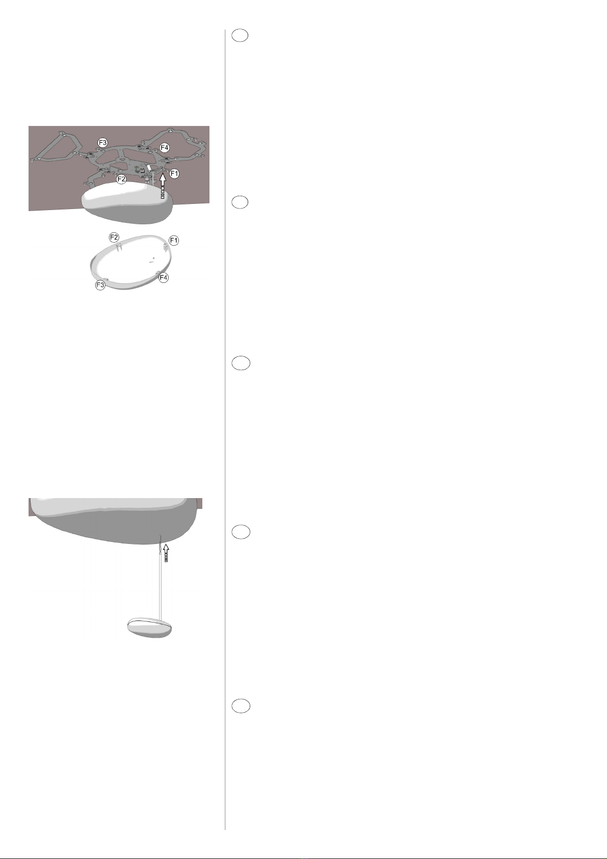
ISTRUZIONI DIMONTAGGIOMODULOSINGOLO
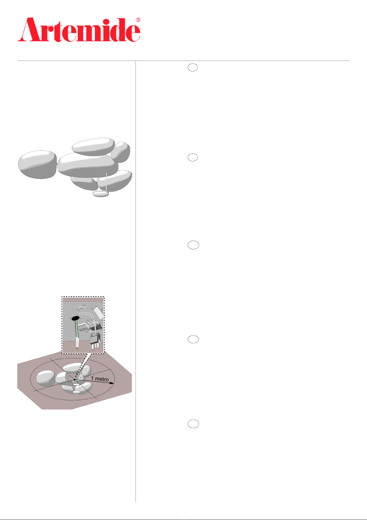
Importante! Prima di procedere all’installazione, verificare che lo spazio di soffitto delimitato da una
circonferenza di 1m di raggio, centrata sul punto luce, sia libero da ostacoli (fig.2).
Questo consente di orientare la composizione aproprio piacimento senza rischi di interferenza con altri
oggetti. Qualora lo spazio libero sia inferiore, l’apparecchio può essere installato uguamente, ma solo
in determinate posizioni, da verificare molto attentamente prima di forare il soffitto. Per garantire il
corretto montaggio dei sassi cromati ènecessario che le strutture installate siano in piano. Compensare
eventuali avvallamenti inserendo spessori tra la struttura ed il plafone nella sola zona delle bugne di
alloggiamento dei tasselli.
fig. 1
fig. 2
AVERTISSEMENT
Déconnecter la tension de réseau avant toute opération sur l’appareil.
Employer exclusivement les ampoules du type et de la puissance indiqués sur la plaque de l’appareil.
ARTEMIDE S.p.a. décline toute responsabilité pour les produits modifiés sans autorisation préalable.
ATTENTION Au moins deux personnes sont nécessaires pour installer correctement l’appareil.
En casd’assemblage sur dessupportsmobiles(ex.faux plafonds), vérifier attentivement que ces
supportsassurentuncontraste adéquatavant de suivre lespasdécritsdans lesfigures21-22.
ISTRUCTIONS DEMONTAGE MODULE UNIQUE
Important! Avantdeprocéderàl’installation,vérifierquel’espacedeplafonddélimitéparunecirconférence
de 1m de rayon, centréesur lepoint de lumière,soit libred’obstacles(fig.2).
Cela permetd’orienterlacompositioncommeon désiresans risques d’interférenceavec d’autres objets. Si
l’espace libre est inférieur,l’appareilpeutêtre installé maisseulementdansdespositionsdéterminéesqui
doivent êtrevérifiéestrèsattentivement avantde percerle plafond. Pour assemblercorrectementlespierres
chroméesilfautqueles structuresinstalléessoient nivelées parfaitement. Compenserlesdénivellations
éventuelles eninsérant descalesentrelastructure et le plafond seulementdanslazone desbossages des
chevilles.
NOTE
Prior to any work on the fixture always switch off the mains.
Only use bulbsof the type and wattage indicated on the rating plate.
ARTEMIDE S.p.a. does not shoulder any responsibilities for products which are modified without prior
authorisation.
WARNING At least two people are required in order to install the fixture correctly.
In case of assembly on moving supports (i.e. false ceiling), check carefully that these latters ensure
suitable contrast before following the steps described in figures 21-22.
ASSEMBLYINSTRUCTIONSFOR SINGLEMODULE
Important! Before proceeding with the installation, make sure that there are no obstacles within the
ceiling area delimited byacircumference with aradius of 1m, centered with respect to the light point
(fig.2). This allows you to position your composition as you desire without the risk of interfering with
otherobjects. In case the free spaceis smaller, the fixture can beinstalled allthe same, but only in specific
positions, whichmust bechecked very carefully beforedrilling the ceiling. Toensure the correct assembly
of thechromium-platedstones,the installed structures must beperfectly levelled. Compensatefor
possible depressions byinserting some shims between the structure and the ceiling only in the area of
the seating hollows for the screw anchors.
VORSICHT
Vor jedem Eingriff an dem Gerät die Netzspannung unterbrechen.
AusschließlichLampen verwenden, die demaufdemGeräteschildangegebenenTypundWert entsprechen.
ARTEMIDE S.p.a. nimmt keine Verantwortung für ohne Vorgenehmigung geänderte Produkte an.
ACHTUNG Mindestens zwei Personen sind nötig, um das Gerät korrekt zu installieren.
Im Fall von Montage auf bewegliche Unterlagen (z. B.Zwischendecken) prüfen Sie aufmerksam, daßsie
einen geeigneten Gegensatz gewährleisten, bevor die in Abbildungen 21-22 beschriebenen Schritte
folgen.
MONTAGEANWEISUNGEN DES EINZELMODULS
Wichtig! Vor der Installation prüfen, ob der durch eine um das Lichtpunkt zentrierte Kreislinie mit 1 m-
Radius begrenzte Deckenraum ohne Hindernisse ist (Abb.2).
DasgestattetdieAusrichtungderKombination nach BeliebenohneRisiko einerÜberlagerungmit
anderen Gegenständen. Wenn der freie Raum kleiner ist, kann das Gerät dennoch installiert werden,
dochnurinbestimmten Positionen, dievor der Durchbohrung derDeckezuprüfen sind. ZurGewährleistung
der richtigen Montage der farblichen “Steine” sollen die installierten Struktur eben sein. Zwischenstücke
zwischen der Struktur und der Decke nur in der Zone der Sitze der Dübel.
ADVERTENCIA
Antes de efectuar cualquier operación sobre elaparatodesconectar la tensiónde red.
Utilizar exclusivamentelas bombillasdel tipoy potenciaindicadaenla placa deidentificación.
ARTEMIDES.p.a. no seasumeninguna responsabilidadanteproductosmodificadossinautorización.
CUIDADO Para instalar el aparato del modo correcto, se necesitan por lo menos dos personas.
En caso de montaje en soportes móviles (ej. falsos techos), controlar cuidadosamente que los mismos
puedan soportar el peso de la lámpara antes de efectuar las operaciones descritas en las figuras 21-22.
INSTRUCCIONES DEMONTAJE MÓDULO ÚNICO
¡Importante! Antes de efectuarlainstalación,cerciorarse de que en el espaciode techo limitadopor una
circunferencia de 1mderadio,centradaenelpunto de luz,nohaya obstáculos(fig.2).
Esto permite orientar la composicióna su gustosin chocar contra otrosobjetos.Si el espaciolibre es inferior,
elaparatosepuedeinstalarigualmente, perosólo en algunasposicionesaverificarmuycuidadosamente
antes de perforar el techo. Para garantizar el montaje correctode las piedras cromadas, las estructuras
instaladasdebenestarperfectamente niveladas.Compensardesniveleseventuales introduciendo piezas de
llenado entrelaestructura yeltecho sóloenlazona de las cavidades donde se ponenlos tacos.
F
EN
D
E

I
Smontaredalla struttura centrale lacopertura morsetti (fig.3), svitando le tre viti Y.Dopo aver
decisol’orientamentodella composizione, portare la struttura centraleasoffittoposizionando
loscasso Aincorrispondenza delpunto luce(fig.4).Segnare la posizione deitasselli (fig.5).
Forare efissare la struttura centrale (fig. 6). Eseguire icollegamenti elettrici all’apposito morsetto
Bcollegandoilcavo diterra al morsettocontrassegnatoconilsimbolo(fig. 7).
}
A
B
}
fig. 3
fig. 5
fig. 6
fig. 7
~
~
Y
Y
fig. 4
Désassemblerlacouverturebornesdelastructurecentrale(fig.3),endévissantles trois vis Y.
Aprèsavoir décidél’orientation de la composition, porter la structure centrale contre le plafond
enpositionnant l’ouverture Aprèsdupoint de lumière (fig. 4). Marquer la position des
chevilles(fig. 5). Percer et fixer la structure centrale (fig. 6). Brancher àla borne adéquate Ben
connectant le câble de miseàla terre àla borne marquée par le symbole (fig. 7).
Removetheterminalcoverfromthecentralstructure(fig.3)by unscrewingthethree
screws Y.Afterdetermining theorientationofyour composition, bring thecentralstructure
towardstheceiling andpositionopening Anear thelight point (fig.4).Marktheposition
ofthescrewanchors(fig.5).Drilland fixthecentral structure(fig.6).Carryout theelectrical
connectionsto theproperterminal Band connect the earth cable to the terminalmarked
by symbol(fig.7).
Die drei Schrauben Y herausschrauben und die Bedeckung der Klemmen (Abb.3) von der
mittlerenStruktur entfernen. Nach derBestimmungderAusrichtungder Kombinationdie
mittlere Strukture ander Decke positionieren und die Öffnung Amuss an dem Lichtpunkt
(Abb.4) sein. Die Position der Dübel (Abb.5)markieren. Durchbohren und die mittlere
Struktur (Abb.6)befestigen.Die dazu bestimmteKlemme Belektrisch anschließen; das
Erdungskabel mit der mitdem Symbol gekennzeichneten Klemme (Abb. 7) verbinden.
Desmontar la cobertura de losbornesde la estructura central (fig.3), destornillando lostres
tornillos Y.Después dehaberestablecidolaorientacióndelacomposición,llevarlaestructura
centralcontraeltecho poniendolaabertura Acercadelpuntode luz(fig. 4). Marcar la
posición de lostacos(fig. 5). Perforar yfijar la estructura central (fig. 6). Efectuar lasconexiones
eléctricasalborneadecuado Bconectandoelcabledetierraalborneindicado conelsímbolo
(fig. 7).
F
EN
D
E
~
Y

Allentare ipomoli Ced aprire i5chiavistelli di fissaggio delle strutture laterali (fig. 8).
Posizionareunastrutturalaterale negli appositiscassidellastruttura centrale echiuderei
chiavistelliavvitando ipomoli(fig.9).
Segnare laposizione dei tasselli (fig. 10).Smontarela struttura,forare, rimontareserrando
bene tuttiipomoli efissare con itasselli (fig. 11).Eseguire lemedesime operazionianche
perlealtre strutturelaterali.
fig. 8
fig. 9
~
~
C
C
fig.10
fig. 11
I
F
EN
D
E
Desserrer les poignées Cetouvrir les 5loquets de fixation desstructureslatérales(fig. 8).
Positionner une structure latérale danslesouvertures adéquatesdela structurecentraleet
fermerles loquets en vissant lespoignées (fig. 9).
Marquerlapositiondeschevilles(fig.10).Désassemblerlastructure, percer,réassembler
en serrant bien touteslespoignéeset fixer àl’aide deschevilles(fig.11). Effectuer les
mêmesopérationspourlesautres structures latéralesaussi.
Loosen knobs Candopenthe5lockbolts oftheside structures (fig.8).Positionaside
structure in the properopenings of the central structureand closethe locking boltsby
screwingknobs (fig. 9).
Mark the positionofthescrewanchors (fig.10).Disassemble thestructure,drill,assemble
againbytighening all the knobsand fix bymeansof the screw anchors(fig. 11). Carryout
thesame operationsalso fortheothersidestructures.
Die Knöpfe Clockern unddie 5Riegel zur Befestigung der seitlichen Strukturen (Abb. 8)
öffnen. Die seitliche Strukturin den dazu bestimmten Öffnungendermittleren Struktur
positionieren und die Knöpfe (Abb.9)anschrauben.
DiePositionderDübel(Abb. 10)markieren. DieStruktur ausbauen, durchbohrenund
wieder montieren; alle Knöpfe spannen und mit den Dübeln(Abb.11) befestigen.Dieselben
Verfahren auch für dieanderen seitlichenStrukturen ausführen.
Aflojarloselementosesféricos Cyabrirlos5pasadoresdefijaciónlaterales (fig. 8).Poner
unaestructuralateral en lasaberturas adecuadasdelaestructura centralycerrarlos
pasadoresatornillandoloselementosesféricos(fig. 9).
Marcarlaposicióndelostacos (fig. 10).Desmontarlaestructura,perforar,montar
nuevamenteapretando todosloselementos esféricosyfijarcon lostacos(fig. 11).Efectuar
lasmismas operacionestambiénparalasdemás estructuraslaterales.

Calzareiguantiprotettivi eliberaredalleprotezioni ilsasso grandeeilcorpoilluminante.
Inserirela lampadina come indicato nella sezione INSERIMENTO/SOSTITUZIONEDELLALAM-
PADINA. Avvicinareil sassogrande allastrutturacentraleorientandoloinmaniera chele sigle
postesullepiastrineinternedel sassocorrispondanoconquellepresentivicinoaipernisferici
della struttura(fig. 12).
Prestando la massima attenzioneanonrovinare la finituradel sasso, estrarreil corpo
illuminantedall’interno delsasso elasciarlopenzolaresottolostesso.Infilarel’astinadi
sostegnonelforo del sasso (fig. 13).
fig. 12
fig. 13
I
F
EN
D
E
Porter lesgantsde protection et libérer la pierre grande et le corpsd’éclairage desprotections.
Insérer l’ampoule comme indiqué danslasection INSERTION/REMPLACEMENTDEL’AMPOULE.
Placerlapierregrandecontrelastructurecentrale enl’orientant de façonque lessigles
placées surlesplaquesàl’intérieurde lapierrecorrespondentavecceux présentsprèsdes
pivotssphériquesde la structure (fig.12).
Extraire le corpsd’éclairage de l’intérieur dela pierre, en faisant trèsattention àne pas
abîmer le finissage de la pierre, et le laisser pendre sousla pierre elle-même. Insérer la tige de
supportdansletrou delapierre (fig.13).
Wear protective glovesand removethe protectionsfrom thebig stone and the illuminating
body.Insertthebulb as shown in theBULBASSEMBLY/REPLACEMENT section.Bring thebig
stonenearthecentralstructurepositioning it sothatthemarks onthe internalplates ofthe
stonecorrespond tothe marks nearthe sphericpins ofthe structures(fig. 12).
Removethe illuminating body from the inside of thestone, being very careful not to damage
thestone finishing,andleave itdangle underthestone. Insert the supportingrodin the
stone hole (fig.13).
Schutzhandschuhe tragenunddie Schutzvorrichtungen und den Beleuchtungskörper von
dem großen Stein entfernen. Die Glühlampe wiein demAbschnitt STECKEN/ERSATZDER
GLÜHLAMPEangegebenstecken. DengroßenSteinan diemittlere Strukturrücken und so
ausrichten,dass die auf den inneren Platten befindlichen Kennzeichen denjenigen
entsprechen,dienebendenkugeligenStiften (Abb.12) derStruktur sind.
Darauf achten, die zugerichteteOberfläche desSteins nicht zu beschädigen, den
Beleuchtungskörper von der Innenseite desSteins entfernen und unterdemStein
herabhängen lassen. Die Stützstangein dasLoch desSteins(Abb.13) stecken.
Llevar losguantesde protección yquitar lasproteccionesde la piedra grande ydel cuerpo de
iluminación. Introducir la bombillacomoindicadoenla secciónINTRODUCCIÓN/SUSTITUCIÓN
DELA BOMBILLA. Acercar la piedra grande ala estructura central para que lassiglascolocadas
en lasplacasinterioresde la piedra correspondan con aquellasque seencuentran cerca de
lospernosesféricos de la estructura(fig. 12).
Extraer el cuerpo deiluminación dela parte interior dela piedrateniendo cuidadoconno
dañar el acabado dela piedramisma ydejarlo colgarbajo la piedra. Introducir la varilla de
soporteenelagujerodelapiedra (fig.13).

Avvitare fino in fondo la manopola Dsull’estremità filettata.
Far scorrere sul cavo il dado Eela rondella dentellata Ffino atoccare il connettore (fig. 14).
Infilare il cavo elettrico nell’appositoscassoposto sul supporto di fissaggio. Inserire l’astina
di sostegno nell’appositasede sagomata del supporto inmodo cheil corpo illuminantesia
disposto come in figura 15.
Mantenendoilcorpo illuminante in posizione, far scorrerelarondelladentellataedildado,
quindi avvitarloamanoall’astina di sostegno.
Mediantelachiaveindotazione completareilfissaggiosenzaserrareafondoildadoper
evitareeventualidanneggiamentidellastruttura(fig. 16).
Svitare lamanopola Dfino abloccarla contro il supporto.
Eseguireil collegamentoelettricoconnettendo idue spinotti (fig. 17).
~
D
~
~
E
F
fig. 14
fig.15
fig.16
fig. 17
~
D
I
F
EN
D
E
Atornillar completamenteelmango Denlaextremidadroscada.
Hacerdeslizarla tuerca Eylaarandela dentada Fsobre el cable hasta tocar elconector (fig.
14). Introducirelcable eléctricoenlaaberturaadecuada en elsoportedefijación. Introducir
la varilla de soporteen el espaciocorrespondiente del soportepara que el cuerpo de
iluminación seencuentreen la posición indicadaen la figura 15.
Manteniendo el cuerpode iluminación ensuposición, hacer deslizar la arandela dentaday
la tuerca; sucesivamente, atornillarlomanualmente ala varilla de soporte.
Mediantelallaveentregada, completarlafijaciónsinapretarcompletamente la tuercapara
evitar dañar la estructura (fig. 16).
Destornillarel mango Dhasta bloquearlo contrael soporte.
Efectuarlaconexióneléctricaconectandolosdosenchufes(fig.17).
Visser complètement la poignée Dsur l’extrémité filetée.
Faireglisserl’écrou Eetlarondelledentée Fsurlecâblejusqu’àtoucherleconnecteur(fig.
14). Insérer le câble électrique dansl’ouverture adéquate placée sur le support de fixation.
Insérer la tige de support dansle logement adéquat profilé du support de façon que le corps
d’éclairagesoit positionné commeindiqué dansla figure 15.
Entenantlecorpsd’éclairageenposition,faireglisserlarondelledentéeetl’écrou,ensuite
levissermanuellementàlatigedesupport.
Al’aidedela cléfournie compléter la fixation sansserrer complètement l’écrouafin d’éviter
des endommagements éventuels delastructure(fig. 16).
Dévisser la poignée Djusqu’à la bloquercontrele support.
Brancherenconnectantlesdeux broches(fig.17).
Completelyscrew knob Don the threaded end.
Make nut Eand notchedwasher F slideonthe cable until theytouch theconnector (fig.
14). Insert theelectric cableinthe proper openinglocatedonthe fixing support.Insertthe
supportingrodin theproper shaped seatof the supportsothattheilluminating body is
positionedas indicated in figure15.
While holding the illuminating body in the correct position, make the notched washer and
thenut slide,thenscrewit by handto the supporting rod.
Complete the fixing operationbymeansofthe suppliedkey withoutcompletelytighening
thenut in order toavoiddamaging the structure (fig. 16).
Unscrewknob D untilit is lockedagainst thesupport.
Carry out the electric connection byconnectingthe two plugs(fig.17).
DenKnopf Dauf demgeschnittenenEndevollständiganschrauben.
DieMutter Eund die gezähnteUnterlegscheibe FaufdemKabel gleiten lassen, bissie den
Stecker(Abb.14) erreichen.Das elektrischeKabel indiedazubestimmte Öffnung auf der
Befestigungsstütze einziehen. Die Stützstange indendazu bestimmtenprofilierten Sitz der
Stütze sostecken, dassderBeleuchtungskörper wie inAbbildung 15 positioniert ist. Den
BeleuchtungskörperinderrichtigenPositionhalten,diegezähnteUnterlegscheibeunddie
Mutter gleiten lassenund dann anderStützstangemanuell anschrauben
Die Mutter durch denmitgelieferten Schlüsselnicht vollständig anschrauben (Abb.16), um
zuvermeiden, dieStrukturzubeschädigen.
DenKnopf Dabschrauben,bis ergegendie Stützeblöckiert wird.
DiezweiStecker (Abb.17) verbinden.

Rimontare lacoperturamorsetti, avendocuradi alloggiareal suo interno tutta la ricchezza
di cavoprovenientedal soffitto(fig. 18).
Far fuoriuscire ilcavo delcorpo illuminante dall’apposito scasso(fig.19)ed icavi provenienti
dall’alimentatoredalloscasso più grande,avendocuradi nonschiacciarlisottoil bordo
dellacopertura(soloversioniHQI).
ATTENZIONE:L’apparecchioèprovvistodi funidisicurezzaperimpedirel’eventuale
cadutadei sassidecorativi.Connettere glispinotti Gprimadifissareisassiallastruttura
(fig. 20).
Spingereilsassocromato versola strutturacentrale,centrandoneiperni Hcon lesedi
internealsassostesso.Secorrettamentecentrati,loscattodeipernirisulteràmolto“dol-
ce”enonsarà necessario forzareeccessivamente.Una volta avvertito loscatto controllare,
tirando leggermente il sassoversoil basso, che tutti iperni siano regolarmentein sede. In
tal casonon sidevono avvertire giochi (fig. 21).
Liberaredalleprotezioni irimanenti sassiemontarliallestrutturerelative, seguendo la
corrispondenza dellesigle tra sede eperno. Verificare sempreilcorrettomontaggio come
descritto in precedenza (fig.22).
~
H
fig. 21
fig. 22
fig.18
fig.19
I
F
EN
D
E
Réassembler lacouverturebornes en faisantattentionàplacer àson intérieur toutesles
partiesexcédentairesducâblesortantduplafond(fig.18).
Fairesortirlecâbleducorpsd’éclairagedel’ouverture adéquate (fig. 19)etlescâbles
sortant de l’alimentateur de l’ouverture la plusgrandeen faisant attention àne pasles
écrasersous leborddelacouverture(seulementversions HQI).
ATTENTION: L’appareil est pourvudecâblesde sécurité afind’empêcherlachuteéventuelle
despierres décoratives.Connecterlesgoupilles Gavantdefixerles pierres àlastructure
(fig. 20).
Pousser la pierrechroméevers lastructurecentrale, en centrantlespivots Havecleslogements
àl’intérieurde lapierre elle-même. Si centrés correctement, lespivots seront fixéstrès
“doucement”et il neserapasnécessairede forcerexcessivement.Une foisle blocage
effectué,contrôler, entirant légèrement la pierre versle bas,quetouslespivots soient
régulièrement dansle logement. Dansce cas,desjeux ne doivent pasêtre présents(fig. 21).
Libérerles pierresrestantesdesprotectionsetlesassemblersur lesstructures relativesen
suivantlacorrespondancedes sigles entrele logementetle pivot. Vérifiertoujours
l’assemblagecorrect commedécrit avant(fig. 22).
Fitthe terminal coveragain, being carefultoputinside it alltheexcess cablescomingfrom
theceiling (fig.18).
Make thecableofthe illuminatingbodycomeoutoftheproperopening(fig.19) andthe
cables comingfrom the feedingdevicecomeoutofthelargeropening beingcareful not to
squashthemunderthe cover edge (HQIversionsonly).
WARNING:The applianceisprovided with safety cablespreventingdecorativestones
from possibly falling. Connectclamps Gbeforefixing the stonestothe structure (fig.20).
Pushthe chromium-platedstonetowards thecentral structureand center itspins Honthe
internalseats ofthestoneitself.Ifcorrectlycentered, thepinswillbe fixedinasimpleway
withoutexcessive pressure.Afterhearingtheclick,makesurethatallthepins arecorrectly
positionedin theirseatsbyslightly pulling thestone downward.In this case there are no
clearances(fig.21).
Free the remaining stonesfrom protectionsand mount them onthe relevant structures,
observing the correspondence of the marksonthe seat and on the pin. Alwayscheck the
correctassemblyaspreviously described(fig. 22).
DieBedeckungderKlemmen wiedermontierenunddenKabelüberhang,derausder
Deckeankommt (Abb.18) indieseBedeckung stecken.
DasKabel desBeleuchtungskörpersausder Öffnung (Abb. 19) unddieKabel, die ausdem
Zuführer ankommen, ausdergrößeren Öffnung herausziehen.Darauf achten, die Kabel
nichtunter demRand derBedeckungzuquetschen(nur Versionen HQI).
ACHTUNG:DasGerätistmitHilfsseilenausgestattet,umdenFallvondendekorativen
Steinenzu vermeiden.Vorder Befestigung der Steinean der Struktur sind die Stifte G
anzuschliessen (fig.20).
DenverchromtenSteinnachdermittlerenStrukturschieben,dieStifte Humdieinneren
Sitze imStein zentrieren. WenndieZentrierungrichtigausgeführt wird,werdendieStifte
ohnezu vielenDruck befestigt. Nachdemein“Klick” gehörtwird,denSteinleicht nach
untenziehenundsich vergewissern,dassalleStifteindenSitzenrichtig sind.(Abb. 21)Auf
diesen Fall sollen keine Spiele vorliegen.
DieSchutzvorrichtungenvon den Steinenentfernenund an den entsprechendenStrukturen
montierenund dieÜbereinstimmungzwischendemSitzunddemStiftbeachten.Prüfen,ob
die Montage richtig ausgeführt worden ist(Abb.22), wie esfrüher beschrienen wurde.
Montarnuevamente lacoberturadelosbornes,poniendoensu interiortodalapartede
cableprocedentedeltecho(fig.18).
Hacersalirelcabledel cuerpodeiluminacióndelaaberturacorrespondiente (fig. 19) ylos
cablesprocedentesdel alimentadordelaaberturamás grande,teniendocuidadoconno
aplastarlosbajo la cobertura (sólo versionesHQI).
CUIDADO: El aparatoestádotado concuerdasdeseguridadparaimpedir lacaídade
laspiedrasdecorativas.Conectar losdispositivos defijación Gantesde fijarlaspiedrasa
la estructura (fig. 20).
Empujarlapiedracromadahacialaestructuracentral,centrandolospernos Hconlos
espacios enlaparteinteriordela piedramisma.Siestán centrados correctamente,los
pernos se engancharánfácilmentesinesfuerzos excesivos. Despuésdelenganche,tirar
ligeramente lapiedra haciaabajoycerciorarsedequetodoslos pernosesténensu espacio
correctamente.Eneste caso,nohay juegos (fig.21).
Quitarlasprotecciones delasdemáspiedras yfijarlasasusestructuras,verificando la
correspondenciadelassiglasentreespacioyperno. Verificarsiempreelmontaje correcto
segúnlodescritoanteriormente(fig. 22).
fig. 20
~
G

INSERIMENTO/SOSTITUZIONEDELLALAMPADINA
Rimuovere il vetrodi protezione I conle relativemolletirandolo versol’alto.Sostituirela
lampadina Lerimontareascattoil vetro elemolle (fig. 23-24).
ATTENZIONE:la lampadina aalogeni non deve essere toccata con lemani.
Qualoraciò avvenga ènecessario pulirla con alcool.
fig. 23
~
I
L
~
fig. 25
LAMPADINA
AMPOULE
BULB
GLÜHLAMPE
BOMBILLA
HALO: MAX 200W HDG R7s
HQI: 70W MTG8,5
I
F
EN
D
E
INSERTION/REMPLACEMENT DEL’AMPOULE
Enlever leverredeprotection I avec lesressortsrelatifs enletirant versle haut.Remplacer
l’ampoule Letréassembler le verre et lesressorts(fig. 23-24).
ATTENTION:l’ampoule halogène nedoit pasêtre touchée avec lesmains.
Si cela seproduit, ilfaut la nettoyer avec de l’alcool.
BULB ASSEMBLY/REPLACEMENT
Removetheprotection glass I with itsspringsbypullingitupward.Replacebulb Land
mountthe glass andthe springsagain (fig. 23-24).
WARNING:the halogenbulbmustnot betouched withbarehands.
Ifthis happens, clean it withalcohol.
STECKEN/ERSATZ DER GLÜHLAMPE
Das Glasnachobenziehenunddas Schutzglas I unddieentsprechenden Federn
entfernen. DieGlühlampe L ersetzen und dasGlasund dieFedern (Abb.23-24) wieder
montieren.
ACHTUNG:DieHalogenglühlampe darfmit denHändennichtberührtwerden.
Wenn daspassiert, soll die Glühlampe mit Alkohol gereinigtwerden.
INTRODUCCIÓN/SUSTITUCIÓNDE LABOMBILLA
Quitar el vidriode protección Icon susmuellesextrayendoelmismohaciaarriba.Sustituir
labombilla Lymontarnuevamente elvidrioylos muelleshastasubloqueo(fig.23-24).
CUIDADO:la bombillahalógenano sedebetocar con lasmanos; de todasformas,en
casode contacto, esnecesario limpiarla conalcohol.
fig. 24
HALO
HQI I
~

Avvertenzegenerali
apparecchidi
illuminazione
per interni
Avertissements généraux
pourappareils
d’éclairaged’intérieur
General warnings for
indoor lightfittings Generelle Hinweise
für Beleuchtungsgeräte
für Innenräume
Adverteciasgenerales
paraaparatosde
iluminación parainterior
Tutti iprodotti ARTEMIDE cherientrano nell’ambito diapplicazione della direttivaeuropeabassatensione B.T.2006/95/CE
soddisfanoirequisiti richiesti erecanolamarcatura “ ”.
Touslesproduits ARTEMIDE appartenant au champ d’application deladirectiveeuropéennebassetension B.T. 2006/95/CE
remplissentlesconditionsprévuesetportent lemarquage “ ”.
All ARTEMIDE productsfalling within therange of application of theEuropeanlow voltage directive B.T. 2006/95/EC meet the
requiredspecifications and bear“ ”labelling.
AlleProduktevon ARTEMIDE,dieunterdasAnwendungsgebietdereuropäischenRichtliniederNiederspannungB.T.2006/
95/EG fallen,entsprechen denerforderlichenEigenschaftenund tragendas “ ”Kennzeichnen.
Todoslosproductos ARTEMIDE quepertenecen alámbitode aplicación de ladirectiva europea de bajatensión B.T.2006/95/
CE cumplen losrequisitoscorrespondientesyllevan elmarcado “ ”.
Artemide si riserva diapportare modifiche tecniche estrutturalinecessarieal miglioramento del prodottoin qualsiasi momento.
Artemideseréserve d’apporter àn’importequel moment toutemodification techniqueet structurellequ’on trouvenécessaire pour l’amélioration
duproduit.
Artemidereserves therighttointroduce allthetechnical andstructuralchangesrequired fortheimprovementofthe product.
Artemide behältsich vorjederzeit,die zurAufbesserung desProduktsnotwendigentechnischen und strukturellenÄnderungen zu bringen.
Artemidesereservalafacultaddeaportarlasmodificaciones técnicas yestructurales necesarias paraelmejoramientodelproductoencualquier
momento.
Attenzione: lasicurezzaelettricadiquestoapparecchioègarantitaconl’uso appropriatodiquesteistruzioni.Pertantoènecessarioconservarle.
Attention: lasécuritédel’appareil n’estgarantiequesilesinstructionssont convenablement suivies.Il est doncnécessaire de lesconserver.
Warning: thisequipment isguaranteed only when used as indicatedin these instructions.Therefore they should bekept for future reference.
Achtung: dieSicherheitderLeuchtewird nur beisachgerechtem Gebrauch gemäßAnweisungen gewährleistet.BittebewahrenSie diese
sorgfältig auf.
Atencion: la seguridad del aparato está garantizada sólo utilizando correctamente lasinstrucciones. Por lo tanto esnecesarioguardarlas.
Incasodi reclamocitareilnumero
Encas deréclamation,veuillezciterlenuméro
In case of complaint, pleasequote number
Beijeder Reklamation gebenSie,bitte folgendeNummer an
En casode reclamación indicar el número
cod. Y503001720 rev.C
ViaBergamo,18
I-20010Pregnana M.se(MI) -ITALIA
t.+39 02.935.18.1f. +3902.935.90.254-496
info@artemide.com
www.artemide.com
P.Iva IT 00846890150
NOTA: Utilizzareesclusivamente un panno morbido eunasoluzione diacqua ealcooldenaturato al10%(dieciparti diacqua eunadi alcool) per
pulirel’apparecchioeglielementidecorativi.
NOTE: Utiliserseulementunchiffon soupleetunesolution d’eau et d’alcool dénaturéà10%(dix partiesd’eau et unepartied’alcool)pour nettoyer
l’appareil et lesélémentsdécoratifs.
NOTE: Only useasoft cloth andasolutionof water and denatured alcohol (ten partsof water andonepart of alcohol)in order to clean thefixture
and the decorative elements.
ANMERKUNG: Das Gerätund die Dekorationselemente ausschließlich mit einem ineiner Lösungvon Wasser und 10%denaturiertem Alkohol
(zehnTeilenWasser undeinemTeilAlkohol)getränktenweichenTuchreinigen.
NOTA:Usar sólo un trapo blando yuna solución de agua yalcohol desnaturalizado al 10%(diez partesde agua yuna de alcohol) para limpiar el
aparatoyloselementosdecorativos.
-Sostituiregli schermi di protezionedanneggiati utilizzando esclusivamenteil ricambioARTEMIDE.
-Remplacer lesécransde protection endommagés en utilisantexclusivementla pièce de rechange ARTEMIDE.
-Replacethedamagedprotectionscreens onlyusing theARTEMIDE sparepart.
-DiebeschädigtenSchutzschirmeersetzen.BenutzenSienurdasErsatzteilARTEMIDE.
-Sustituirlas pantallasde protección dañadas utilizandoexclusivamenteelrepuesto ARTEMIDE.
Table of contents
Other Artemide Lighting Equipment manuals
Popular Lighting Equipment manuals by other brands

LARSON
LARSON EPL-MJ LED Series instruction manual

Cembre
Cembre CBL02-W Operation and maintenance manual

LUMEN CENTER ITALIA
LUMEN CENTER ITALIA VENDOME Assembly instructions

Paramount Fitness
Paramount Fitness MDX-R3 Owner's manual and installation guide

Stairville
Stairville Stage Quad LED Bundle RGB WW user manual

Chauvet DJ
Chauvet DJ Intimidator Free Spot 60 ILS user manual