Arthur Grillo WR 200-F Operating and installation instructions

Heat Meter WR 200-F
electronic computing device for heat quantity measuring
Description and Operation
Heat transfer medium water or other liquids
any ow sensor with analog signal connectable
2 temperature inputs for Pt100 in four-wire circuit
exact calculation of the heat parameters according IAPWS-IF97
built-in clock with automatic calendar to 2099
Counters for heat quantity and ow rate
backlit alphanumeric LCD display 4x20 characters
resettable counters for adjustable periods
2 pulse outputs for M-Bus connection (optional)
Housing for locking rail or wall mounting
4 analog outputs for instantaneous values
Accessories for panel mounting

Safety Instructions
2
!
Attention! Please read these instructions carefully before you connect
the device and put it into operation. The unit includes touch-hazardous
voltages, that may only be connected and put into operation by qualied
and experienced personnel.
Table of Contents Page
Precautions 2
Application 3
Description 4
Assembly 5, 6
Dimensions, location of terminals 7
Wiring diagram 8
Start up 9
Setting the period counter 10
Display WR 200-F 11,12
Setting date and time 13
Conguration 14, 15
Specications 16

Application
The heat meter WR 200-F is used to detect the heat energy in closed heating or cooling
systems using a liquid heat carrier. The heat energy from the current heat output according
to the formula
P = heat output in kW
P = Q · ∆T · k Q = Flow in m3/h3/h
∆T = Temperature difference between ow-
and return temperature in °C
k = Thermal coefcient in kWh / m3·°C
calculated integrated over time and summed on a 9-digit counter.
The ow rate is also added up to another counter.
The heat coefcient k is calculated for water in the range of 0 ..
250 ° C as a function of ow and return temperature and the location of the ow measure-
ment. Basis for calculating are material properties for water according IAPWS-IF97.
For other heat carriers (e.g. Water-brine mixtures or thermal oil) can be considered equiva-
lent thermal coefcients in the unit.
3

4
Description
The heat meter WR 200-F is a microcontroller-controlled computing device for detecting the
heat energy in heating systems with thermal water or other uids (water-glycol mixtures or
thermal oil). The counting of the thermal energy and the amount of heat carrier is on a 4-line
alphanumeric LCD display with backlight. Through a key scan, all measured and calculated
values are shown with their physical units, date and time.
The heat meters have a built-in clock with automatic calendar up to 2099. Thus in adjustable
periods, energy counts are available via resettable counters.
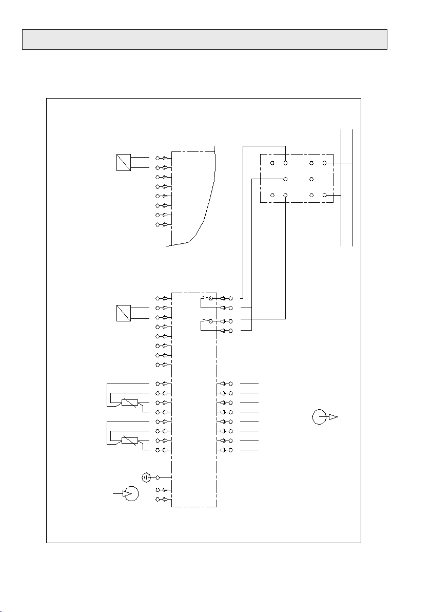
The temperature of the heat meter inputs are provided for RTD Pt100 DIN 43760 in four-
wire circuit.
To the ow input, any transmitter with the signal range 0 ..20 mA or 4 ..20 mA can be con-
nected. A two-wire transmitter with the signal range 4 .. 20 mA can also be connected,
supplying the transducer is now performed directly from the heat meter.
The characteristic line of ow input can be set linear or square root.
An analog output circuit provides 4 analog signals 0 ..20 mA or 4 ..20 mA. The analog
signals supplied from the calculation circuit and galvanically separated with respect to a
common earth terminal.
For external processing of the counts pulse outputs are provided. Here as an option a M-
Bus loggers can be connected.
For the power supply the voltage 230 V 50 Hz is required. A built-in backup battery secures
the counts during a power failure.
The heat meters are housed in an aluminum prole housing for snap-rail mounting. For
installation in a control panel corresponding mounting hardware is provided. For wall mount-
ing, the heat meter can be mounted in a plastic housing with IP55 protection.

5
Assembly
1. Cabinet installation on 35 mm DIN prole rail.
The aluminum prole housing is designed for direct mounting on a 35 mm DIN prole rail.
2. Mounting into a panel (panel mount).
For installation in a control panel, the mounting kit 58010 is required.
Provide panel cut-out 135 mm x 76.5 mm.
135
76,5
144
4,2
Fix the front frame.
Install heat meters from behind into the panel using mounting rods
152
86
Arthur Grillo GmbH · Ratingen
Wärmezähler WR 200
Panel cut-out
Mounting inside the panel

6
Assembly
3. Wall mounting in a plastic housing.
For mounting on a wall, the heat meter is installed in a plastic housing with IP55 protec-
tion.
Arthur Grillo GmbH · Ratingen
Wärmezähler WR 200
218
166
112,5
M-Count
The M-Bus Logger M-Count 2C may be incorporated directly into the plastic housing.

7
Baumaße und Lage der Anschlussklemmen
Wärmezähler WR 200
Arthur Grillo GmbH · Ratingen
Analog outputs
Pulse outputs
Mains connection
Temperature
Inputs
Flow
input
The heat meter WR 200 is connected via plug-in terminals.
964 4 1
16 19
28 27
50 57
Position of the terminals on the heat meter
106
134
Wärmezähler WR 200
Arthur Grillo GmbH · Ratingen
72
PE terminal

8
Wire diagram
910 11 60 6461 6362 34 8 7 2 6 5 1 28
L
27
N
535150 52 54 55 56 57
1716 1918
Wärmezähler WR 200-F
Netz
230 V 50 Hz
Vorlauftemperatur
Rücklauftemperatur
=
Q
+ -
Durchfluss
(∆p)
Durchfluss
(∆p)
+
Q
=
-
6010911 6261 63 64
Vorlauftemperatur
+ - -+
Rücklauftemperatur
+ -
Durchfluss
+ -
Wärmeleistung
Analogausgänge 0/4...20 mA
M-Bus
M-Count
2C Impuls m3
Masse
Impuls MWh
aktiver Messumformer
0/4...20 mA
Zweileiter-Messumformer
4...20 mA

9
Start up
The heat meters WR 200 are pre-congured according to customer requirements and ready
for operation after connecting all sensors and are applying the power supply according to
wiring diagram on page 8. (Changing the conguration see page 13).
After turning on the power in the display the counters for heat quantity and ow rate are
indicated:
Heat quantity
W = 0000000.01 MWh :
Flow rate
V = 00000000.2 m3 :
Button to display switch
The ashing colon indicates the internal count. If the heat capacity or the ow rate = 0, the
associated colon is in position "on" or "off".
Next, the current date and time are set. Use the button to switch to the date and time
display switch:
Heat counter WR200-F
Device no. 10.657
Mon 03/06/2010
Time 12:48:22
Button to display switch
Setting the clock
Mon 03/06/2010
Time 10:49:00 AM
value lower
value higher
next value
previous value
after setting the value for the seconds and press the "Next value"
the display returns to the measurement mode and the clock is ticking.
Press the "Set Clock"

10
Setting the period counter
Heat quantity 1
W= 0000063.06 MWh :
Flow rate 1
V= 00000371.7 m3 :
Button to display switch
In the next step date and time will be set to stop the cycle counter. Put display to the heat
quantity 1 and ow rate 1:
Counter 1 stops at
Mon 01/12/2010
Time 03:55:27 PM
value lower
value higher
next value
previous value
after setting the value for the seconds, the cycle counter will be set to zero and counting
restarts
Heat quantity 1
W= 0000000.00 MWh :
Flow rate 1
V= 00000000.0 m3 :
Button to display switch
Button to set

Display WR 200-F
Heat meter WR200-F
Device no. 10.657
Mon 03/06/2010
Time 12:48:22
Button to display switch
Date and time display
The alphanumeric LCD display with 4 lines of 20 characters is used to display various pa-
rameters of the heat meter.
Heat quantity
W = 0000012.37 MWh :
Flow rate
V = 00000352.6 m3 :
Button to display switch
The ashing colon indicates the internal count. If the heat capacity or the ow rate = 0, the
associated colon remains in the position "on" or "off.
VLT = 138.50 °C
RLT = 85.20 °C
dT = 53.30 °C
k = 1.173 kWh/m3·°C
Button to display switch
Q = 125.3 m3/h
P = 7.83 MW
Button to display switch
Abbreviations
W measured heat quantity k heat coefcient
V counted ow rate
VLT Supply temperature Q Current owrate
RLT Return temperature P Current heat output
dT delta T = VLT - RLT
11

12
Display WR 200-F
Conguration:
Qmax = 200.0 m3/h
Pmax = 10.00 MW
Measuring in the ow
Button to display switch
Conguration:
Input Q: 4-20mA
Characteristic: linear
Outputs : 0-20mA
Button to display switch
Display conguration parameters
The ashing colon indicates the internal count. If the heat capacity or the ow rate = 0, the
associated colon remains in the position "on" or "off".
Heat quantity 1
W= 0000063.06 MWh :
Flow rate 1
V= 00000371.7 m3 :
Button to display switch
Counter 1 stops at
Fri 05/08/2010
Time 08:00:00 AM
Button to display switch
Display of resettable cycle counter
Alarm time and date display
When reaching this date and this time the cycle counters will stop
Heat quantity 1 and ow rate 1

13
Setting date and time
Heat meter WR200-F
Device no. 10.657
Mon 03/06/2010
Time 12:48:22
Button to display switch
Display with button for display switch to
Date / time provide
Setting the clock
Mon 01/12/2010
Time 03:55:27 PM
Press button
Setting the clock
Mon 01/12/2010
Time 03:55:27 PM
Value lower
Value higher
Next value
previous value
after setting the value for the seconds and pressing the button "next value"
the display will return to date / time
Heat meter WR200-F
Device no. 10.657
Mon 03/06/2010
Time:48:22

14
Conguration
Attention! In conguration mode, the meter does not count!
To access the conguration level, the button to change the conguration should remain for
at least 16 seconds.
Heat quantity
W = 0000012.37 MWh :
Flow rate
V = 00000352.6 m3 :
Button to change the congu-
ration settings
Setting parameters:
Qmax= 200.0 m3/h
Settings higher
Settings lower
Move cursor
Setting parameters:
Qmax= 200.0 m3/h
Move decimal place
to the next parameter
Setting parameters:
Qmax= 200.0 m3/h
Measuring in return
Exchange forward / return
to the next parameter

15
Conguration
Setting parameters:
Qmax= 200.0 m3/h
measuring in the re-
turn
Exchange linear / square root
to the next parameter
Signal range:
Input Q: 0-20 mA
Exchange 0-20 / 4-20 mA
to the next parameter
Signal range:
Input Q: 0-20 mA
Outputs : 0-20 mA
Exchange 0-20 / 4-20 mA
return to the measurement

Arthur Grillo GmbH · Am Sandbach 7 · 40878 Ratingen
Phone 0 21 02 - 47 10 22 · Fax 0 21 02 - 47 58 82
06.12
Heat transfer: Water or other liquids
(Water-glycol mixtures, heat transfer oil)
Temperature range: -50...+250 °C
Temperature inputs: 2 x Pt100 four-wire circuit for ow and
return temperature, no compensation required
Flow input: 0/4-20 mA, direct supply of two-wire transmitters,
supply voltage approximately 18 Vdc
Characteristic of the ow input Linear or square root
k-value: Determination according to data from IAPWS-IF97
Display: backlit alphanumeric LCD display, 4x20 characters,
all counts and current readings are
displayed with their physical unit
Counters: 9-digit number for the summation of heat quantity
and ow rate
Cycle count: 9-digit resettable counters, cycle adjustable via built-in
clock and calendar
Clock: built-in clock with automatic calendar to 2099
Backup battery: Lithium battery backs up the accumulated
counts in case of power failure
Outputs: 4 analog outputs 0/4...20 mA for the following current values:
Flow temperature, return temperature, ow,
heat output
2 pulse outputs for heat and ow rate
M-Bus (optional): M-Bus Logger M-Count 2C
Housing: Aluminum prole housing for mounting on
35 mm DIN prole rail, measures 134x106x72 mm (WxHxD),
Protection type acc. EN 60529 Front IP55, terminal side IP20
Connection via screw terminals (Combicon)
Wall-mount housing: Polystyrene with hinged transparent front cover
Dimensions 218x166x112, 5 mm (WxHxD), protection type IP55
Panel mounting: Kit consisting of front frame, mounting rods
and xing screws
Supply voltage: 230 Vac
Power consumption: about 4 VA
Weight: about 600 g, wall-mounted unit 1.5 kg
EMC: Interference emission acc EN 61000-6-3,
Immunity acc EN 61000-6-2
Accuracy: in accordance with DIN EN 1434 for heat meter-computing devices
Specications
Table of contents
Other Arthur Grillo Measuring Instrument manuals
Popular Measuring Instrument manuals by other brands

Horiba Scientific
Horiba Scientific DS-72G instruction manual

Yamato
Yamato TA300 instruction manual

Keysight
Keysight N9010AK-MTU Installation note

Vanguard Instruments
Vanguard Instruments ATRT-03 Software Operating Guide

PCE Health and Fitness
PCE Health and Fitness PCE-PA6000 Operation manual

Buchi
Buchi NIR-Online PA2 Operation manual

Gossen MetraWatt
Gossen MetraWatt PROFITEST MF Series Short-form operating instructions

Milwaukee
Milwaukee MW170 MAX instruction manual

Hubbell
Hubbell Aclara RF Electric I-210+c user guide

AlazarTech
AlazarTech ATS9146 user manual

TESTO
TESTO 540 instruction manual

Free2Move eSolutions
Free2Move eSolutions MIDcoounter Erratum of installation and user manual