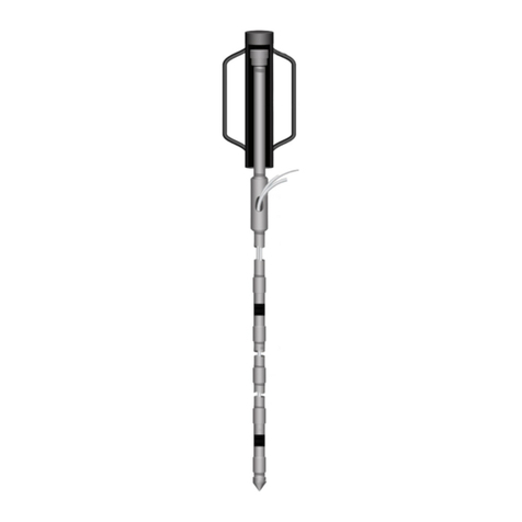
Waterloo Multilevel System Assembly Manual
Page 4
3.0 Preparation
The number and specific order in which each component of the System are to
be assembled must be determined ahead of time. The depths of the desired
monitoring zones and layers of backfill (where applicable) must be determined in
advance of the installation. The design log will serve as a reference during the
install. Ensure that an ‘as built’ installation log is maintained. See Appendix I for
an example of a “Waterloo System Installation Log”.
Before the install date, reconfirm that the borehole is still open to its target
depth. Once the Waterloo System is received, make sure that the shipment
looks complete and that nothing appears damaged. Contact Solinst immediately
to resolve any issues before proceeding with the install.
If a Solinst Trainer is requested, the training will be completed in its entirety,
prior to starting the installation. See Appendix IV for the Terms and Conditions
of training.
The System weighs about 1 lbs/ft., which doesn’t include the weight of the
Packers. Therefore, at least two physically strong field assistants will be needed
to lower the System by hand. If the depth to water is more than 100 ft. (30 m)
below ground surface, then a hoisting winch (drilling rig) will be needed to assist
with holding and lowering the System via an optional support cable.
Tools and equipment you should bring for the installation:
• Appropriate safety precautions and equipment to ensure a safe
working environment at your site
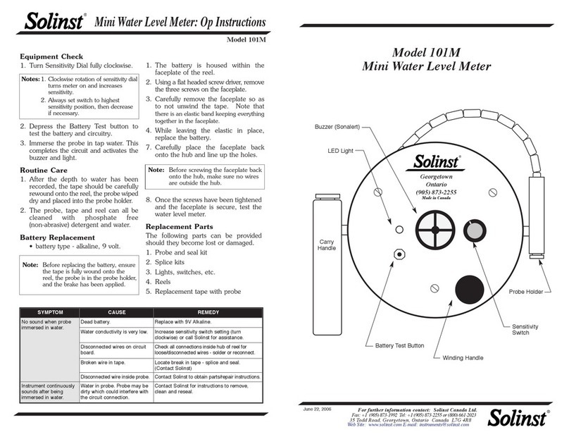
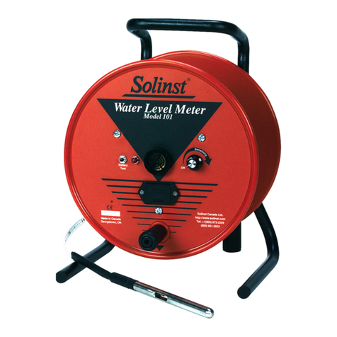
• Water Level Meter/Well Depth Indicator
• Lights and/or security if the installation goes beyond daylight hours or
more than 1 day is needed to complete the installation
• Plastic sheeting to keep the Waterloo casing, tubing, etc. clean when
being laid out on the ground during installation
• Pylons or traffic cones for safety and to identify the lay down area or
work zone
• Hand-spray water bottle used to lubricate pipe joints
• Two 5 gal pails
• One roll of black electrical tape to temporarily identify the ports and
associated pump tube discharge ends
• 11/16" (18 mm) and 5/8" (16 mm) wrenches
• Hacksaw - to achieve desired System stick-up
• Large dowel or spindle
• Small piece of sand paper to assist in pushing tubing over the pump
stems
NOTE
In designing the layout, it is
preferable to allow one to two feet
of clearance above the bottom
of the borehole. Problems of
measurement inaccuracy, sloughing
during installation, and other
unforeseen events which may
prevent well completion are thus
minimized.
NOTE
If the depth to water is greater than
100 ft. (30 m) below ground surface,
lower the system with the support
cable and drilling rig.
NOTE
Be sure to document the position
and placement of each downhole
component, during the installation.
An ‘as built’installation log is a
crucial part of knowing where each
monitoring zone is placed.
