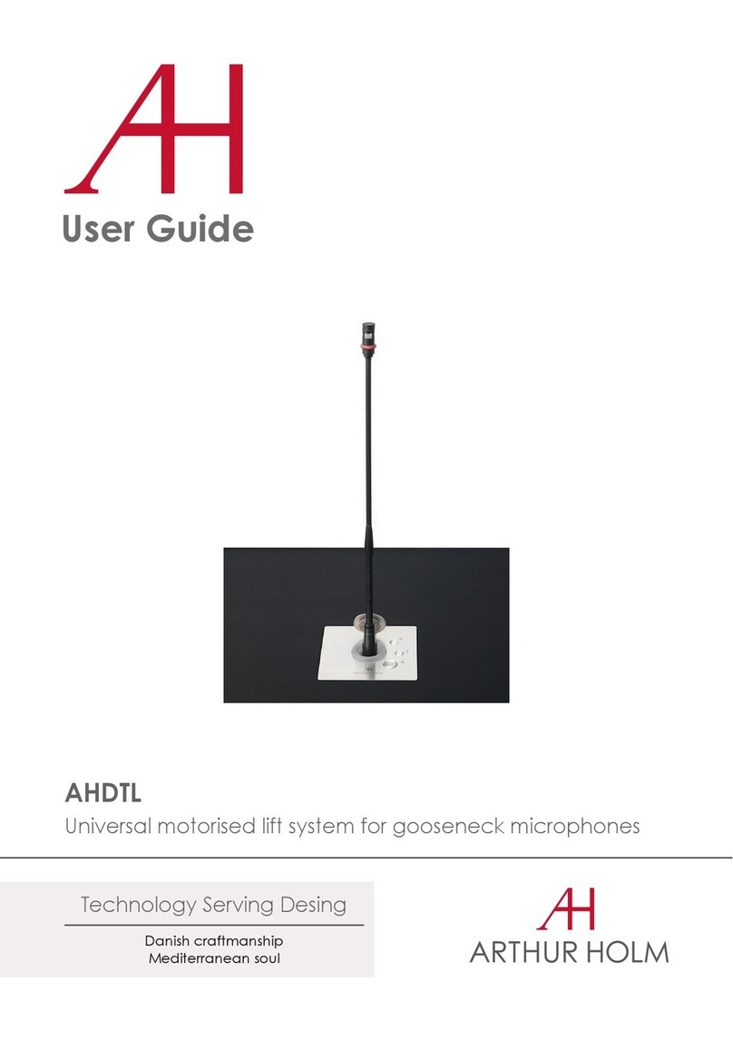
ARTHUR HOLM DynamicTabLift User manual

User Guide
Danish craftmanship
Mediterranean soul
Technology Serving Design
DynamicTabLift

TABLE OF CONTENTS
REGULATIONS AND SECURITY 5
SAFETY INSTRUCTIONS 5
SYSTEM DESCRIPTION 7
INSTALLATION INSTRUCTIONS 8
POWER AND CONTROL 9
CONTROLS 10
AHnet PROTOCOL 11
INFORMATION ON DISPOSAL 14
WARRANTY TERMS AND CONDITIONS 15

WELCOME
Thank you for purchasing an ARTHUR HOLM product.
Please, read this installation and operating instructions carefully and keep
them in a safe place for future reference.
We remain at your entire disposal if you have any suggestions.
Henrik Holm
General Manager

ABOUT US
The Company
Arthur Holm has its origins in the Danish furniture designer Jorgen Alex
Jensen, who was active during the sixties and the seventies. His design
inspiration and his concept of ergonomics have been continued by his
family, who is the design force behind Arthur Holm product range. The
result of combining Scandinavian design tradition with Mediterranean
creativity, exibility and emotion is a wide product range built on more
than 25 years of craftsmanship.
Arthur Holm offers a professional product range where tomorrow’s
technology is shaped into valued materials with design exibility and
customisation, specially created to enhance communication in reception,
collaboration, conference and meeting areas.
The art of customisation
Arthur Holm offers a range of ingenious products whose designs are based
on quality materials and the latest technology. Products which endow
meeting and conference rooms with silent, ergonomic, innovative and
aesthetic solutions that integrate into the furniture, hang from the walls as
works of art or are used as interactive points of information.
The world of Arthur Holm
Arthur Holm offers a selection of unique, elegant, versatile, exible and
ergonomic products that are being used in meeting and conference
rooms, reception areas, huddle rooms, control rooms, auditoriums and
public zones of leading companies throughout the world.
The numbers speak for themselves! We currently own 33 product patents,
have presence in over 45 countries with products and solutions inmore
than 25,000 installations.
It will be our pleasure to work with you, designing your unique and
personalised environment. Our broadcast electronic engineers will
provide the latest technology while our design team will offer you the most
exclusive appearance.
Our team puts its heart, passion and pride in all our designs.

5
SAFETY INSTRUCTIONS
Plugs
• Do not dismantle any part of the unit power connector.
• Disconnect the power plug from the AC outlet when the unit is not
going to be used for an indenite period of time.
Power and extensions cords
• Use the appropriate power cord with the correct plug type.
• Do not overload wall outlets or power cords.
• Make sure the total ampere passed through an extension cord does not
exceed the maximum allowed by the cable used.
• Do not place anything on the power cord.
• Do not locate this product where a person may walk or trip over the
cord.
REGULATIONS AND SECURITY
ATTENTION: Do not disassemble or modify the device in any way.
This symbol warns of the presence of dangerous un-insulated
voltages inside some of the components, of sufcient magnitude
to expose people to risk of electronic shock.
This symbol draws attention to important use and maintenance
instructions in the manual that accompanies the unit.
This symbol indicates that the equipment conforms to the norms
established by the European Community.
This symbol indicates D.C. current.

6
Wiring connected to hazardous voltage requires installation by
qualied personnel or the use of ready-made exible cables.
For your security, your equipment must be connected to an
electrical outlet with grounding connection protection.
Since the plug is used to disconnect the device, the operating
electrical outlet must be in an easily accessible place.
Environment
• Install the equipment on an elevated, at surface.
• Install the equipment in a ventilated area.
• Avoid exposing the equipment to:
∙Rain or water
∙Excessive heat, cold or humidity
∙Area exposed to direct sunlight
∙Dirty areas
∙Equipment generating strong magnetic elds
• Avoid placing open containers of liquid, near the equipment.
• Keep a minimum distance of 30 mm in order to have good ventilation.
• Never place above the device any sources of ames such as lighted
candles, etc.
• If you are using the device in extreme weather conditions and/or
tropical climates, the equipment should be installed in a room which
ensures a reasonable level of temperature and humidity.
• To prevent damage the equipment must be rmly anchored to the
surface, as shown on the installation instructions.
SAFETY INSTRUCTIONS

7
SYSTEM DESCRIPTION
General
DynamicTabLift is a motorised lift system for tablets. You can easily link
your tablet when there's no need to break on a walking enviroment.
Features
• Motorised lift system for tablets
• Adaptable to tablets under request
• Revolving system for horizontal and vertical positions
• Serial control & Remote diagnosis
Box Contents
Before the installation of your retractable unit, please check the
contents of the shipping box, it must contain the following items:
• Unit
• Power cord
• Remote control (1 per 5 units)
• Power supply 100-2 40Vac, 50-60Hz. Output 12V
• User guide
Power connection
CAUTION: Never use this device in horizontal position
1. Plug the power cable from the power supply into an AC socket of
100-240 Vac, 50-60Hz.
2. Plug the 12V D.C. cable into the socket on the unit.

8
INSTALLATION INSTRUCTIONS
Instructions
Fitting the tablet:
To place the tablet on the support, the support must be on vertical
position (minimum inclination).
Once the support is in this position, pull the clip up and place the tablet
against the support. To ensure a correct t, press it while holding the clip
up.

9
POWER AND CONTROL
12V D.C. :Power supply input connector. XLR-4 connector.
- 1,2: Ground
- 3,4: 12Vdc
GPI: Unit external contact close control. SubD9 female.
1. GPI1 +
2. GPI1 –
3. GPI2 +
4. GPI2 –
5. GPI3 –
6. GPI3 +
7. N.C.
8. +12Vdc (600mA max.)
9. Ground:
- Use GPI1 (1:12Vdc, 2: Ground) to open the unit
- Use GPI3 (6:12Vdc, 5: Ground) to close he unit
Termination: Activate (ON) the termination. Only on the last unit of the RS422
bus.
AHnet: RJ45 CAT6 connector for addressable RS422 control. There is a loop through
connector to use as signal RS422 output. Up to 30 units can be connected on the
same RS422 bus.
Service: Used for rmware's upgrade.

10
CONTROLS
On the upper cover plate, there are two buttons to control the UP and
DOWN movements function:
1. Raising the tablet:
To rise up the unit, press the rear button (1) on the right hand side of
the cover plate.
2. Retracting the tablet:
To retract the unit, press the front button (2) on the right hand side
of the cover plate.

11
AHnet PROTOCOL
Communications protocol
COMMUNICATION RS422
CONNECTION RJ45
WIRING CAT-6
Speed and conguration
BAUD RATE 38400
DATA BITS 8
PARITY NONE
STOP BITS 1
Wiring Diagram
1. Data TX +
2. Data TX –
3. Data RX +
4. NC
5. NC
6 .Data RX –
7. NC
8. NC
Connection
PINS 1 & 2 The units respond
PINS 3 & 6 The units receive instructions
Protocol to control the unit by addressable RS422 bus.
You can connect up to 30 units on the same RS422 bus.
You can use an AH Interface Ethernet, to control the RS422 bus.
The units should have a set address and the address must start by 1.
Maximum cable length between ends: 500 m/1640 ft.
RJ-45

12
AHnet PROTOCOL
AHnet protocol
Uses 5 bytes communication:
BYTE 0 START BYTE
BYTE 1 ADDRESS BYTE
BYTE 2 COMMAND BYTE
BYTE 3 VALUE 1
BYTE 4 VALUE 2
Commands
COMMAND DESCRIPTION RESPONSE
FA XX 01 01 00 GO UP FB XX 01 01 00
FA XX 01 00 00 GO DOWN FB XX 01 00 00
FA XX 04 01 00 BUTTON LOCK FB XX 04 01 00
FA XX 04 00 00 BUTTON UNLOCK FB XX 04 00 00
FA XX 14 00 00 INQUIRY CONTROL BYTE FB XX 14 CB1 CB2
XX Number of the unit address. Up to 30 units for each RS422 BUS
CB1 Response in 8 bites of the unit status
CB2 Response in 8 bites of the unit status

13
AHnet PROTOCOL
CB1
BITE 76543210
CLOSED 1 1 0 1
OPENED 0 1 0 1
PROTECT STOP 1
LIFT OK 0
CB2
BITE 7 6 5 4 3 2 1 0
BUTTON LOCK 1
BUTTON UNLOCK 0
To send an order to all the units, you must use the address:
249 Dec. (Byte1)
F9 Hex. (Byte1)
In this case, the units do not respond

14
AHlink
AHlink is used to control and set-up the unit.
By default, the AHlink wireless signal is deactivated. To activate it,
please press and hold simultaneously the Open and Close buttons on
the cover plate for 5 seconds.
You can also activate the AHlink wireless signal by using the Interactive
Setup Display (ISD) located below the monitor. Press successively the
Down arrow until the AHlink appears on the LCD screen. Then, press the
OK button and you will hear a 5 Beep sound. This means that the AHlink
is active.
The wireless AHlink signal
automatically deactivates when
there is no device connected
during more than 2 minutes.
When the AHlink deactivates,
you will hear a long Beep sound.
To control and set up your AH
product with AHlink, please
download it from the App Store
(IOS system) or from Google Play
(Android system) and execute it
in your handled device.
It is recommended on to select
Auto Connect and select Portrait
on Orientation. To connect it,
select Scan for local devices.

15
AHlink
If your AH device does not
appear on the screen, the
AHlink signal might no longer be
active.
The AHlink name always begins
with the characters “AH”
followed by the four last MAC
AHlink address. You must select
the AH device.
After selecting the AH device,
the rst page will upload on
your screen. This page is used
for the basic installation setup.

16
AHlink
SERIAL
Serial number of the unit
VER
Firmware version
MOV
Controls the Up and Down monitor movements
AHLINK OFF: Turns off the AHlink signal
COMMAND: Information of the last AHnet
command received from RS422 port
SENSORS: Indicates sensor status.
S1 Unit up position
S2 Tablet rotation
AHnet ADDRESS: AH address settings
POSITION: Tablet position
PASSWORD: Access to the factory's settings

17
INFORMATION ON DISPOSAL FOR USERS OF WASTE ELECTRICAL &
ELECTRONIC EQUIPMENT
This symbol on the products and/or accompanying
documents means that used electrical and electronic
products should not be mixed with general household
waste.
For proper treatment, recovery and recycling, please
take these products to the designated collection
points, where they will be accepted on a free
of charge basis. Alternatively, in some countries,
you may be able to return your products to your
local retailer upon the purchase of an equivalent
new product.
Disposing of this product correctly will help save valuable resources
and prevent any potential negative effects on human health and the
environment, which could otherwise arise from inappropriate waste
handling. Please contact your local authority for further details of your
nearest designated collection point.
Penalties may be applicable for incorrect disposal of this waste, in
accordance with national legislation.
For business users in the European Union
If you wish to discard electrical and electronic equipment, please contact
your dealer or supplier for further information.
Information on disposal in countries outside the European Union
This symbol is only valid in the European Union. If you wish to discard this
product, please contact your local authorities or dealer and ask for the
correct method of disposal.

18
WARRANTY TERMS AND CONDITIONS
Albiral Display Solutions warrants this product against manufacturing
defects and workmanship for a period of two (2) years from the date of
purchase, subject to the conditions below.
1. Electrical, electronic boards, accessories and power supply are
warranted against manufacturing defects and workmanship for a
period of two (2) years from the date of purchase
2. Labour costs: Albiral Display Solutions covers the labour costs to
replace any defective parts during the validity of this warranty.
3. Transport costs:
5.1. In the case that a manufacturing defect occurs within 90 days
after the purchase date, both freight and insurance costs will be
paid by Albiral Display Solutions.
Although Albiral Display Solutions S.L. pays for freight and
insurance costs, Albiral Displays Solutions will not be responsible
for any damages caused by the transportation of the goods
if the customer does not inform in writing when receiving the
goods.
5.2. After 90 days of the purchase date, the beneciary of the
warranty will pay both freight and insurance costs.
Albiral Display Solutions S.L. will not be responsible for any
damages caused by transportation, when this one is paid by
the customer.
4. This warranty does not cover the labour costs of handling, diagnose,
removal, replacement, reinstall and/or program any product.
5. This warranty does not apply if the fault has been caused by misuse,
improper handling, electrical or mechanical abuse, abnormal
operation conditions, non-authorised modications, and inadequate
transportion or as a result of atmospheric phenomenons.

19
WARRANTY TERMS AND CONDITIONS
6. The warranty is not valid if people other than authorised Service
Centre have handled the product and if the product has been
manipulated or warranty seals are removed or manipulated.
7. The beneciary of the warranty will have to return the product with
the original packaging to warranty there are no damages during
transportation.
8. The warranty is not valid if the beneciary of the warranty does not
include a RMA form and a copy of the purchasing invoice.
Please note that laws vary from country to country, and the same
provisions of this warranty may not apply to you.
If you have any doubts concerning the terms of this warranty, please
contact:
+34 938 502 376
Copyright ©
Dec. 2020. All rights reserved
Albiral Display Solutions SL.
Registered trademarks: Albiral, Arthur Holm

Patents
MU17180ES00
MU17301ES00
MU17322ES00
MU17413ES00
MU17445ES00
MU17854ES00
MU17868DEPC
MU17868RUPC
P24821DEEP
P24821ESEP
P24821GBEP
P24821USPC
P27178DEEP
P27178EPDV01
P27178EPPC
P27178ESEP
Fàtima 25, Sant Hipòlit de Voltregà
08512 Barcelona – Spain
tel: +34 93 850 23 76 / 23 83
fax: +34 93 850 25 50 / 23 72
web: www.arthurholm.com
e-mail: [email protected]
This manual can be modied without previous notice. ENG – December 2020
P27178ITEP
P27178RUPC
P27178USPC
P27284DEEP
P27284EPPC
P27284ESEP
P27284GBEP
P27284RUPC
P27284USPC
P27715ESEP
P28089DEEP
P28089ESEP
P28089ITEP
P28089USPC
P28090EP00
P31160ESES
P31160PCES
201201.11
Table of contents
Other ARTHUR HOLM Lifting System manuals