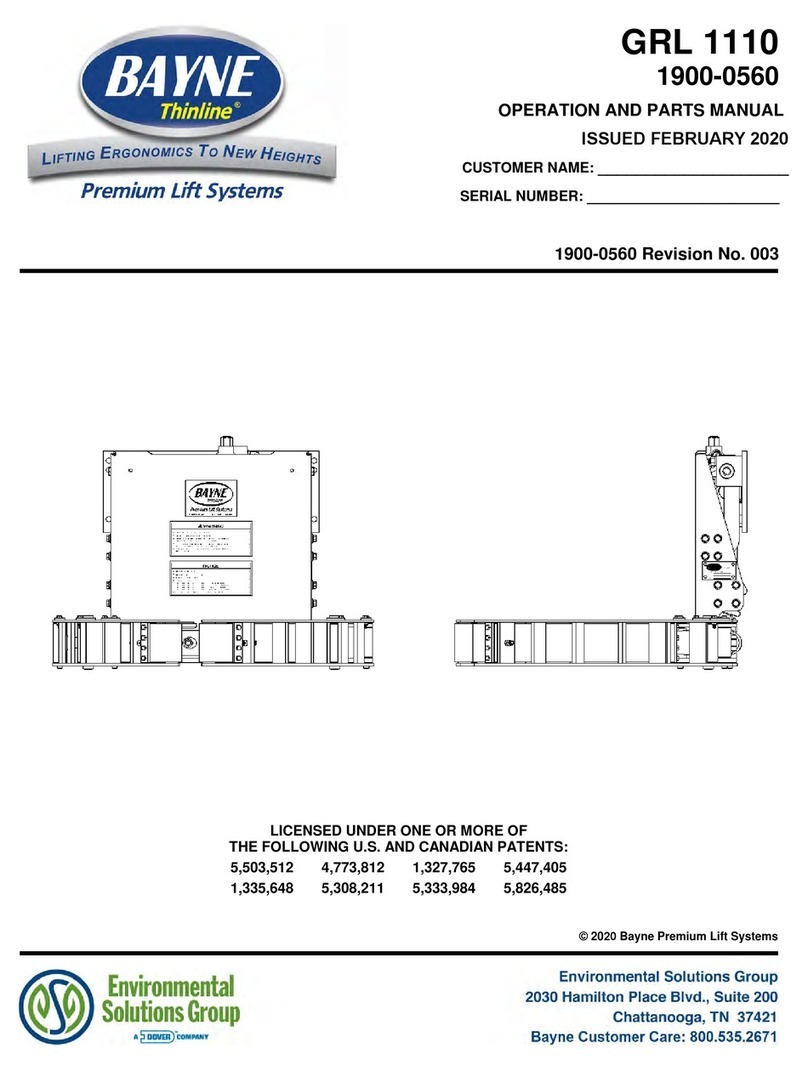
Bayne THINLINE GRL 1110 3/8" KEYWAY Guide

OPERATION AND PARTS MANUAL
MODEL NUMBER :
PART NUMBER :
SERIAL NUMBER :
BAYNE MACHINE WORKS, INC. PHONE: 864.288.3877
910 FORK SHOALS ROAD TOLL FREE: 800.535.2671
GREENVILLE SC, 29605 FAX: 864.458.7519
LICENSED UNDER ONE OR MORE OF
THE FOLLOWING U.S. AND CANADIAN PATENTS:
5,503,512 4,773,812 1,327,765 5,447,405
1,335,648 5,308,211 5,333,984 5,826,485
GRL 1110 3/8” KEYWAY
1900-0571

Document Number: 1900-0571 Issue Date: 05/21/13 Revision No: 001 Page: 2 of 39
TABLE OF CONTENTS
Page
I. THINLINE
®Specifications 3
II. THINLINE
®Installation Instructions 5
III. THINLINE
®Operation Instructions 9
IV. THINLINE
®Maintenance Instructions 10
V. THINLINE
®Actuator Assembly Instructions 11
VI. Trouble-shooting Chart 23
VII. Appendix A
1. Unit Assembly Drawings 26
2. Mounting Height Drawing 38
3. Hydraulic Schematic Drawing 40

Document Number: 1900-0571 Issue Date: 05/21/13 Revision No: 001 Page: 3 of 39
SPECIFICATIONS ( WI-0091-A )
Bayne THINLINE
®
Premium Lift Systems
A. Rotary Actuator - rack and pinion style design.
• Rack, pinion, and shaft bearings are constantly lubricated by the hydraulic oil for
extended life.
• Body and caps are made of high quality ductile iron.
• Pinion output shaft and racks are made of high tensile alloy steel.
• The rotary actuator provides smooth motion throughout the lift cycle, which results in
longer cart life with virtually no cart damage or abuse.
B. Arm bearings are made of a composite material which provides superior compression
strength along with self-lubrication, thus eliminating the need to grease the arm bearings.
C. The THINLINE
®
lift unit can measure as little as 7 1/8” thick from the back of the
mainframe to the front of the lifter, depending on the types of arms used.
D. The faceplate is normally at 45 degrees in the dump position and extends 10” to 12” from
the back of the mainframe into the hopper or container opening. This places the cart or
barrel 13” to 15” into the truck or container opening thus reducing any potential spillage
of materials.
E. Cycle times for safe, fast, efficient service.
• 6 - 8 seconds for Actuator to rotate up and down.
• 3 - 4 seconds for GRL arms to clamp and unclamp.
Note : Cycle time is controlled by flowrate, as flowrate increases, cycle times decrease.
Warning : Never exceed the cycle times listed above. In order to avoid injury and maintain
manufacturer’s warranty never operate outside of these recommendations.
F. Recommended flow rates are as follows:
• 2 to 2 1/2 GPM for 1100 series units
• 2 to 4 GPM for 2200 series units
G. Hydraulic pressure requirements are as follows:
• 1800-2000 PSI normal working pressure
• 3000 PSI maximum pressure

Document Number: 1900-0571 Issue Date: 05/21/13 Revision No: 001 Page: 4 of 39
H. All lifters can be a bolt on type installation for easy, quick maintenance and less
downtime.
I. All parts are manufactured and kept in stock at Bayne Machine Works, Inc. for fast
response to customer request.
J. Two ( 2 ) year limited warranty from date of delivery on all units and models when
properly maintained and operated within the recommended cycle time.
All lift units and parts are inspected by our Quality Control Department before shipment to
insure that you always receive the highest quality available in the lift business.
For more information, please contact us at 1/800/535-2671 or by fax at 1/864/458-7519.

Document Number: 1900-0571 Issue Date: 05/21/13 Revision No: 001 Page: 5 of 39
INSTALLATION INSTRUCTIONS ( WI-0236-A)
Bayne THINLINE
®
Premium Lift Systems
The following information is intended to be a GENERAL GUIDE to installing the Bayne
THINLINE
®
lifter on a typical refuse truck. Before starting the installation, read these
instructions completely. ALWAYS use the proper tools, lift devices, and personal protective
equipment to prevent injury while performing the installation.
NOTE: If a Bayne THINLINE
®
Tap-In Kit was also acquired for this installation, refer to
the installation instructions included in the Tap-In Kit manual for more detailed information.
I. Mounting lifter on the truck :
1. The truck should be emptied and cleaned before any installation. The truck should
be parked on a level solid surface, a concrete floor if possible.
2. All lights, tags, steps, etc. that will interfere with the installation should be removed
and/or relocated.
3. Position the lifter on the sill of the truck per figure I-1 and mounting height drawing
( Appendix A ) and tack weld in place. If using an “S” unit for bolt on applications,
tack weld the mounting plate in place and attach the lifter to the mounting plate
using the 1/2” studs. ( tack weld only at this time so that adjustments can be made if
necessary. ).
figure I-1

Document Number: 1900-0571 Issue Date: 05/21/13 Revision No: 001 Page: 6 of 39
II. Making Hydraulic Connections :
Before attempting any hydraulic connections, turn the truck’s engine off and
release all hydraulic pressure from the system. Refer to the hydraulic layout
( figure I-2) and hydraulic schematic ( Appendix A ) while performing the
following steps.
figure I-2
1. Connect the hose from the “UP” port of the rotary actuator to the “C” port of the
dual hand valve.
2. Connect the hose from the “DOWN” port of the rotary actuator to the “D” port of
the hand valve.
3. Connect the hose from the “C” port of the GRL control valve to the “A” port of the
hand valve.
4. Connect the hose from the “UC” port of the GRL control valve to the “B” port of the
hand valve.

Document Number: 1900-0571 Issue Date: 05/21/13 Revision No: 001 Page: 7 of 39
III. Adjusting the GRL control valve :
The clamping pressure and speed of the THINLINE
®GRL lifter’s arms are
controlled by the GRL control valve mounted to the lifter.
It is very important to make sure the hydraulic oil is at operating
temperature, and the flow rate and relief valve settings have been
properly adjusted before setting the GRL control valve pressures.
The proper flow rate and relief settings are 2 gpm at 1800 psi.
The amount of pressure the GRL arms use to clamp the container is controlled
with a pressure relief valve in the GRL control valve. This valve is preset at the
factory to operate with most containers. However, if the lifter seems to be
crushing or loosing grip on your specific containers, refer to figure I-3 while
performing the following steps to properly adjust the clamping pressure.
1. Loosen the lock nut on the pressure relief valve in the GRL control valve.
2. If the lifter is crushing the waste container, turn the adjustment screw counter-
clockwise 1/4 turn. If the lifter is loosing grip on the waste container, turn the
adjustment screw clockwise 1/4 turn.
3. Repeat clamping and dumping the container, making necessary adjustments to the
pressure relief valve in 1/4 turn increments until the lifter securely holds the
container without crushing it.
4. Tighten the lock nut on the pressure relief valve to secure the correct pressure
setting.
figure I-3

Document Number: 1900-0571 Issue Date: 05/21/13 Revision No: 001 Page: 8 of 39
IV. Final operation and mounting:
1. Start the truck’s engine and engage the hydraulic system.
2. Operate the lifter and bleed all air from the hydraulic system.
3. Place a cart on the lifter and operate to make sure there are no clearance problems
and that the lifter engages the cart properly. Make any adjustments to the mounting
position of the lifter to ensure correct operation.
4. After locating an acceptable mounting position, complete the welding of the lifter to
the truck.

Document Number: 1900-0571 Issue Date: 05/21/13 Revision No: 001 Page: 9 of 39
OPERATION INSTRUCTIONS ( WI-0405-A )
Bayne THINLINE
®
Premium Lift Systems
The Bayne THINLINE
®
Premium Lift System is a high quality durable cart lifter built to
meet your industry’s requirements. To insure the safety of all operators of this equipment,
please read this manual carefully before operating the lifter. FAILURE TO COMPLY WITH
INSTRUCTIONS COULD RESULT IN PERSONAL INJURY AND/OR PROPERTY
DAMAGE.
The operating stages ( figure O-1 ) in the cycle of the cart lifter are as follows:
1) START - The cart to be dumped is rolled up to the lifter.
2) CLAMPING - The clamp arms are engaged around the cart.
3) ACTUATOR DUMP - The rotary actuator is cycled to dump the contents
of the cart.
4) ACTUATOR REVERSE - The rotary actuator is reversed, returning the
cart to the ground.
5) UNCLAMPING – The clamp arms are unclamped.
figure O-1
The rotational and clamping motions of the cart lifter are controlled with the use of a dual
hand valve. Moving the grabber arm handle on the dual hand valve in the upward direction
will cause the grabber arms to perform the CLAMPING stage. Moving the actuator handle in
the upward direction will cause the lifter to perform the ACTUATOR DUMP stage. Moving
the actuator handle in the downward direction will cause the lifter to perform the ACTUATOR
REVERSE stage. Finally, moving the grabber arm handle in the downward direction will
cause the lifter to perform the UNCLAMPING stage.

Document Number: 1900-0571 Issue Date: 05/21/13 Revision No: 001 Page: 10 of 39
MAINTENANCE INSTRUCTIONS ( WI-0141-A )
Bayne THINLINE
®
Premium Lift Systems
NOTE:
The most common cause of hydraulic component failure is contamination of the
hydraulic fluid ( water, chips, dirt, etc. ) The Bayne THINLINE
®Lift System
comes clean from the factory. If removed, be sure the hoses, cylinder and
fittings are clean before re-installing them on the unit.
Inspect your dumper on a weekly basis for loose bolts, fittings, oil leaks, etc.
Tighten loose hardware as necessary and replace necessary seals to repair oil
leaks.

Document Number: 1900-0571 Issue Date: 05/21/13 Revision No: 001 Page: 11 of 39
BAYNE
PREMIUM LIFT SYSTEMS
ASSEMBLY INSTRUCTIONS
1100 SERIES ROLLER BEARING ACTUATOR
PART NUMBER 1122-1040 ( WI-1139-B )
LICENSED UNDER ONE OR MORE OF THE FOLLOWING U.S. PATENTS:
4,773,812 1,327,765 5,308,211 5,333,984
READ INSTRUCTIONS COMPLETELY BEFORE STARTING ASSEMBLY.
Before starting the assembly of the Rotary Actuator, refer to the exploded parts drawing and
parts list (fig. A-13 found at the end of these instructions) to familiarize yourself with the
individual components. Prepare a clean surface, in an area free of blowing dust and
contaminants in which to assemble the Rotary Actuator. Be sure that all parts are thoroughly
clean and dry before starting assembly.
NOTE: All torque values given apply to clean dry threads only. Follow these directions
closely when repairing the Rotary Actuator.
1. Install the piston seal load ring (13) (fig. A-1) in the small groove on the head of the
actuator rack (2). Place the “square” piston seal (17) over the load ring (13) in the same
small groove (a small “blunt” flathead screwdriver may be used, taking care not to scratch
or damage the seal). Install the wear ring (18) in the large groove on the head of the rack.
Using a ring compressor, firmly seat the rings on the rack before setting it aside, this will
help to reverse the effects of any stretching of the rings that occurred during installation.
Repeat this procedure for the other rack.
figure A-1

Document Number: 1900-0571 Issue Date: 05/21/13 Revision No: 001 Page: 12 of 39
2. Install the tube seal (12) (fig. A-2) and “square” tube seal backup (16) on each end of the
actuator tubes (3) (fig. A-13). Be sure that the “square” tube seal backup ring is toward
the inside of the tubes at both ends as shown. Press all rings firmly into the grooves.
Repeat this procedure for the other tube.
figure A-2
3. Thoroughly clean the pinion shaft (1) (fig. A-3) and inner races (10) with a mild solvent
and dry completely. Spray the inner race contact area (shown in figure A-3) at each end
of the pinion shaft and the inside diameter of the inner race thoroughly with LOCTITE
7649 N PRIMER. Apply LOCTITE RETAINING COMPOUND 609 around the pinion
shaft at contact area and the inside diameter of the inner races. Slide the inner races (10)
on the pinion shaft (radius end first as shown in figure A-3) until the races seat against the
gear teeth. After the races seat against the gear teeth, twist the races on the pinion 360º to
spread the retaining compound evenly. Wipe off any excess retaining compound.
figure A-3

Document Number: 1900-0571 Issue Date: 05/21/13 Revision No: 001 Page: 13 of 39
4. Place the actuator body (7) (fig. A-4) on the edge of the table, mounting flanges closest to
the assembler with the counter-bores facing up. Insert the pinion shaft (1) through the bore
on either side of the actuator body with the key ways facing back toward the mounting
flanges and up away from the table with the center line of the key ways pointing toward
the center of the tapped hole shown in figure A-4. Center the pinion in the actuator body.
figure A-4
5. Coat the head portion of the racks (2) (fig. A-13) with STP Oil Treatment. Install the
racks, head portion up with the teeth facing the flanges of the actuator body, into the dual
set of bores in the body. Simultaneously slide the racks into the bores so that the racks
mesh with the pinion in the same position. Rotate the pinion shaft to engage the racks into
the pinion.
figure A-5

Document Number: 1900-0571 Issue Date: 05/21/13 Revision No: 001 Page: 14 of 39
6. Check the position of the racks in the pinion by making sure both racks seat against the
actuator body at the same time and also when the racks are seated against the body, the
key ways on the pinion shaft should be facing down toward the table and very slightly
back toward the mounting flanges on the actuator body as shown in figure A-6.
figure A-6
7. Coat one end of the actuator tubes (3) (fig. A-13) around the seal area with STP Oil
Treatment as shown in figure A-7. Using a rubber mallet, drive the coated end of the tube
onto the exposed rack until the tube end seats in the actuator body, making sure that the
seals remain in place as the tube enters the counter-bore. Repeat this procedure for the
other side.
figure A-7

Document Number: 1900-0571 Issue Date: 05/21/13 Revision No: 001 Page: 15 of 39
8. Install the six tie rod studs (6) (fig. A-13) by screwing the short threaded end into the
actuator body. Hand tighten only at this time (the torque needed will be applied later in
the procedure).
9. Place the tube cap (4) (fig. A-13) on the table. Coat the sides of the two bores in the tube
cap with STP Oil Treatment. Install the cap over the tubes and rod studs with the oil port
positioned to the left as shown in figure A-13. Using a rubber mallet, tap the tube cap
over the tubes until the tubes seat in the cap, making sure that the seals remain in place.
10. Place the tube mounting bracket (30) (fig. A-13) over the two end rod studs opposite the
oil port in the tube cap as shown in figure A-13.
11. Install the hex nuts (23) (fig. A-13) and lock washers (24) on the tie rod studs. Torque the
nuts to 50 ft-lb. in the sequence shown in figure A-8.
figure A-8
12. Place the rack cap (5) (fig. A-13) bore side up on the table and coat the edge of each bore
with STP Oil Treatment. Install the rack cap seals (14) (fig. A-9) in the rack cap.

Document Number: 1900-0571 Issue Date: 05/21/13 Revision No: 001 Page: 16 of 39
figure A-9
13. Reposition the actuator on the table mounting flanges down, and the lower tubes facing
away from the assembler. Rotate the pinion shaft to allow 1” of the rack to protrude from
the top of the actuator body. Install the rack cap with the oil port positioned to the left
hand side of the actuator opposite the bottom oil port located in the tube cap as shown in
figure A-13. Attach the rack cap to the actuator body using the socket head bolts (22) (fig.
A-13) and lock washers (26). Torque the bolts to 90 ft-lb. in the sequence shown in figure
A-10.
figure A-10
14. Reposition the actuator so that the pinion shaft can be rotated with no obstacles. Rotate
the pinion shaft to ensure that the racks move freely. Also make sure that the key ways
point perfectly straight “up” toward the rack cap and “down” toward the tube cap at each
end of the 180° stroke. If the assembly does not perform all of these functions correctly, it
must be disassembled, cleaned, and reassembled.

Document Number: 1900-0571 Issue Date: 05/21/13 Revision No: 001 Page: 17 of 39
15. Re-center the actuator pinion in the actuator body by tapping on one end of the shaft with
a rubber mallet. Install the roller bearing (9) (fig. A-13), over the pinion shaft and inner
race, and into the actuator body. Repeat this procedure for the other bearing.
16. Thoroughly clean the bearing caps (8) (fig. A-11) with a mild solvent and lubricate all seal
grooves with STP oil treatment. Place the bearing caps (8) on the table (mounting surface
down) and install the wiper ring (19) in the outside groove using a rubber mallet or small
press. (Avoid using tools that may damage seals or scratch bearing cap or bearing
surfaces.) Turn the bearing cap (8) over. Collapse the pinion seal (20) and carefully
work it into the groove. Use fingers to carefully press the seal completely into the groove
as shown in figure A-11. Be careful not to score or scratch the sealing surface during
the installation. Install the bearing cap seal (15) and thrust washer (32) into their
respective grooves on the bearing cap mounting surface as shown in figure A-11.
17. Coat the bearing cap seal area and pinion seal area shown in figure A-11 lightly with STP
Oil Treatment.
figure A-11
18. Wrap masking tape or electrical tape around the pinion to cover the edges at the keyway.
Slide the bearing cap assembly over the pinion shaft with the bearing cap seal facing
toward the actuator body and the flat surface of the flange shown in figure A-16 facing
toward the actuator mounting flanges. Press against the bearing cap until the shoulder
seats against the actuator body, making sure that the seals remain in place. Install the
bearing cap bolts (21) (fig. A-13) and lock washers (25). Hand tighten only at this time.
Repeat this procedure for other bearing cap.

Document Number: 1900-0571 Issue Date: 05/21/13 Revision No: 001 Page: 18 of 39
19. After both bearing caps have been installed, torque all bearing cap bolts to 30 ft-lb. in the
sequence shown in figure A-12.
figure A-12
20. Install the 90° fitting (27) (fig. A-13) into the oil port on the side of the rack cap (5). Hand
tighten only at this time.
21. Install the 45° bulk-head fitting (31) (fig. A-13) up through the hole in the tube mounting
bracket (30) bolted to the tube cap as shown in figure A-13. The 45° end must be pointing
down away from the rack cap (5) and back toward the mounting flanges on the actuator
body. Hand tighten only at this time.
22. Install the rack cap extension tube assembly (29) (fig. A-13) between the 90° fitting in the
rack cap and the 45° fitting in the tube mounting bracket as shown in figure A-13.
Tighten all connections.
23. Install the orifice plug (11) (fig. A-13) into the oil port on the side of the tube cap (4), and
install the 90° fitting (27) into the oil port over the orifice plug as shown in figure A-13.
Turn the fitting so that it points down away from the rack cap (5) and back toward the
mounting flanges on the actuator body and tighten.
24. Install the cap nuts (28) (fig. A-13) onto the open fittings to prevent contamination of the
unit until the hoses are installed.

Document Number: 1900-0571 Issue Date: 05/21/13 Revision No: 001 Page: 19 of 39
ACTUATOR ASSEMBLY
figure A-13

Document Number: 1900-0571 Issue Date: 05/21/13 Revision No: 001 Page: 20 of 39
BAYNE
PREMIUM LIFT SYSTEMS
ASSEMBLY INSTRUCTIONS
SHORT STROKE SLOWDOWN
PART NUMBER 6011-1210 ( WI-2303-A )
LICENSED UNDER ONE OR MORE OF THE FOLLOWING U.S. PATENTS:
1,327,765 5,308,211 5,333,984
READ INSTRUCTIONS COMPLETELY BEFORE STARTING ASSEMBLY.
The Slowdown is a patented device used to cushion the unit as it completes its rotation into
the dump position. This cushioning prevents the tearing of carts and helps protect the dumper
from abuse. The Slowdown is part of the Actuator assembly and is assembled into the rack
cap.
Before starting the assembly of the Slowdown, refer to the exploded parts drawing and parts
list ( fig. S-4 found at the end of these instructions ) to familiarize yourself with the individual
components. Prepare a clean surface in an area free from blowing dust and contaminants in
which to assemble the Slowdown. Be sure that all parts are clean and dry before starting
assembly.
NOTE: All torque values given apply to clean dry threads only. Follow these directions
closely when assembling the Slowdown.
1. Install the housing seal ( 5 ) ( fig. S-1 ) in the groove next to the hexagon head of the
plunger housing ( 1 ). Place the o-ring ( 6 ) and the square backup ring ( 7 ) in the groove
at the end of the plunger housing as shown in figure S-1.
figure S-1
This manual suits for next models
1
Table of contents
Other Bayne Lifting System manuals
Popular Lifting System manuals by other brands
Hatchlift
Hatchlift RV Bedlift Kit instructions
APlusLift
APlusLift HW-10KBP Installation manual & operation instructions

Titan Lifts
Titan Lifts Master Series Installation, operation & maintenance manual
Maxon
Maxon GPT-25 Operation manual
PFlow Industries
PFlow Industries 21 Series installation manual
Magliner
Magliner LiftPlus Start-up instructions
