ARTHUR HOLM AHDTL User manual

User Guide
Danish craftmanship
Mediterranean soul
Technology Serving Desing
AHDTL
Universal motorised lift system for gooseneck microphones

WELCOME
Thank you very much for acquiring an Arthur Holm product.
Our mission is to provide meeting rooms with solutions featuring exclusive
design and innovative technology to optimise space, share information
and help the decision-making.
Our vision is to facilitate communication through innovative and exclusive
design technology that integrates seamless in the furniture design.
Please, read this guide carefully. If you have any suggestions that might
help us to improve our products, we would be pleased to receive them.
Thank you again and we hope that you enjoy the Arthur Holm experience!
Henrik Holm
General Manager

TABLE OF CONTENTS
EC REGULATIONS AND SECURITY 6
SAFETY INSTRUCTIONS 6
APPLICATIONS 8
FEATURES 9
BOX CONTENTS 9
CONTROLS 10
CONNECTIONS 12
PRODUCT HANDLING 14
AHNET PROTOCOL 15
AHLINK 18
WARRANTY TERMS 22

6 7
SAFETY INSTRUCTIONS
Plugs
• Do not dismantle any part of the equipment power connector.
• Disconnect the power plug from the AC outlet when the equipment is
not going to be used for an indenite period of time.
Power and extensions cords
• Use the appropriate power cord with the correct plug type.
• Do not overload wall outlets or power cords.
• Make sure the total ampere passed through an extension cord does not
exceed the maximum allowed by the cable used.
• Do not place anything on the power cord.
• Do not locate this product where a person may walk or trip over the
cord.
EC REGULATIONS AND SECURITY
ATTENTION: Do not disassemble or modify the device in any way.
This symbol warns of the presence of dangerous un-insulated
voltages inside some of the components, of sufcient magnitude
to expose people to risk of electronic shock.
This symbol draws attention to important use and maintenance
instructions in the manual that accompanies the unit.
This symbol indicates that the equipment conforms to the norms
established by the European Community.
Wiring connected to hazardous voltage requires installation by
qualied personnel or the use of ready-made exible cables.
For your security, your equipment must be connected to an
electrical outlet with grounding connection protection.
Since the plug is used to disconnect the device, the operating
electrical outlet must be in an easily accessible place.
Environment
• Install the equipment on an elevated, at surface.
• Install the equipment in a ventilated area.
• Avoid exposing the equipment to:
∙Rain or water
∙Excessive heat, cold or humidity
∙Area exposed to direct sunlight
∙Dirty areas
∙Equipment generating strong magnetic elds
• Avoid placing open containers of liquid, near the equipment.
• Keep a minimum distance of 30mm in order to have good ventilation.
• Never place above the device any sources of ames such as lighted
candles, etc.
• If you are using the device in extreme weather conditions and/
or tropical climates, the equipment should be installed in a room
which ensures a reasonable level of temperature and humidity.
• To prevent damage, the equipment must be rmly anchored to the
surface, as shown in the installation instructions.
SAFETY INSTRUCTIONS

8 9
SAFETY INSTRUCTIONS
This equipment has been tested and found to comply with the limits
for a Class B digital device, pursuant to part 15 of the FCC Rules. These
limits are designed to provide reasonable protection against harmful
interference in a residential installation. This equipment generates, uses
and can radiate radio frequency energy, and if not installed and used
in accordance with the instructions, may cause harmful interference
to radio communications. However, there is no guarantee that
interference will not occur in a particular installation. If this equipment
does cause harmful interference to radio or television reception, which
can be determined by turning the equipment off and on, the user is
encouraged to try to correct the interference by one or more of the
following measures:
• Reorient or relocate the receiving antenna
• Increase the separation between the equipment and receiver
• Connect the equipment into an outlet on a circuit different from that to
which the receiver is connected
• Consult the dealer or an experienced AV technician for help
APPLICATIONS
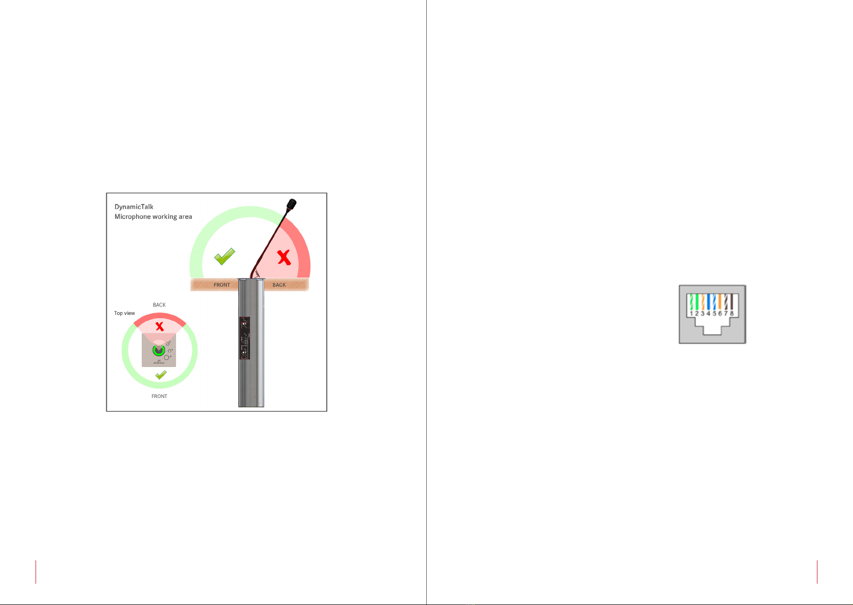
DynamicTalk is an elegant retractable system for gooseneck
microphones with exclusive features. It not only makes the microphone
disappear within the desk surface but it also provides a pleasant light
to indicate its status. Thanks to its protective and patented lighting
ring, the microphones can be safely stored and protected making
meeting and conference spaces more flexible and versatile.
DynamicTalk provides two different working modes: PA and
Conference. When in PA mode, a push button placed on the stainless
steel cover plate allows to activate or de-activate the microphone,
and the LED ring will indicate the status by changing colour from red
to green. The system will automatically silence the microphone when
retracting. When in Conference model, the microphone will always be
active and both the light ring and the access to the push button on
the cover plate will be available via GPI and GPO for remote control.
DynamicTalk is available in 3 sizes: for 400 mm, 500 mm and 600
microphones. The system can be adjusted to the exact length of the
microphone via AHnet and AHlink. The AHlink is an excellent tool to
diagnose, verify and configure DynamicTalk.
Features
• Universal lift system for gooseneck XLR 3 pin microphones
• Stainless steel cover plate with 3 buttons
• LED lighting ring to indicate microphone status, 360º
• Serial control and remote diagnosis
• Individual addressing
• AH-AMMC Auto Mechanical Movement Calibration
• PA and Conference working modes
Box Contents
Before the installation of your DynamicTalk, please check the contents
of the shipping box, it must contain the following items:
• DynamicTalk
• Power cord
• Power supply 100-240Vac, 50-60Hz. Output 12V
• User Manual
Important Note: This device can only work with the power supply
included in the shipping box. This power supply can not be replaced by
any other rather than the original one.
Caution! Never use this monitor in horizontal position.
APPLICATIONS

10 11
Communications protocol
CONTROLS
On the upper cover plate, there are three buttons to control the
functions and to externally control other devices (GPO).
1. UP/DOWN: Controls the elevation and retraction of the microphone
lift. Press this button during 2 seconds to activate AHlink signal (5
beeps sound when AHlink signal is activated).
2. Customised: The central push button is used to control external
devices. The contact close button (GPO) is present on the GPO
connector to externally control other devices. Contact close of the
GPO pins 7, 8 while pressing this button.
3. TALK or GPO: The third push button has two different functions:
• PA mode: In PA mode, this button is used as the MUTE function.
Press the button once and the LED ring will appear in red indicating
that the MUTE function is deactivated and it's ready for the user to
talk to the audience. Press the button again to activate the MUTE
function and silent the microphone, which will be indicated by the
green LED ring. The contact close button (GPO) is present on GPO
connector to externally control other devices. Contact close of the
GPO pins 9, 10 while pressing this button.
• Conference mode: In Conference mode, the microphone is
controlled by the external conference system. This button then, has
no function and the contact close of the push button is present
on the GPO control connector. The contact close button (GPO)
is present on GPO connector to externally control other devices.
Contact close of the GPO pins 9, 10 while pressing this button.
4. Dynamic LED Ring: The system has a LED Ring to indicate the status of
the microphone: RED indicates that the MUTE function is deactivated
and GREEN indicates that the MUTE is activated. When the equipment
is congured to work on Conference mode, the LED Ring is externally
controlled by GPI on the GPI external control connector.
CONTROLS

12 13
CONNECTIONS
AHNET RJ45 CAT5 connector for addressable RS422 control. There is
a loop through connector to use as signal RS422 output. Up
to 30 monitors can be connected on the same RS422 bus
AHNET ADDRESS Shows the AHnet Address congured on this unit
TERM ON Brighting when the RS422 bus termination is active. Activate
only the RS422 bus termination on the last unit of the bus
RX Illuminates when the unit receives a RS422 AHNet command
OSD – OK + - Changing AHnet Address. Press OK button. Change the
AHnet number address using + and – keys, and press OK to
save the new address
- RS422 bus termination. Press + key to activate the RS422
termination. Press – key to deactivate the RS422 termination
GPI/GPO EXTERNAL CONTACT CLOSE CONNECTOR
1. GND
2. Command microphone UP connecting to GND. Connecting
to GND more than 2 seconds, activates the AHlink signal (5
beeps sounds when the AHlin signal is activated)
3. Command microphone DOWN connecting to GND
- Use a pulse signal to RISE and LOWER the microphone
4. Red LED ring brights connecting to GND (only in conference
mode)
5. Green LED ring brights connecting to GND (only in
conference mode)
6. GND
7,8. GPO1. Contact close of the central button located on
cover plate
9,10. GPO2. Contact close of the talk button located on THE
cover plate
SERVICE Used for rmware upgrade
12V D.C. Power supply input connector. XLR-4 connector:
1,2: Ground
3,4: 12Vdc
CONNECTIONS

14 15
PRODUCT HANDLING
Please follow the gure below for a correct product usage of the
DynamicTalk microphones.
To avoid any product malfunctions, do not attempt to bend the
microphone to the incorrect angle or outside the microphone's working
area.
Please note that ware to the microphone and pop screen surface can
occur.
AHNET PROTOCOL
Communications protocol
COMMUNICATION RS422
CONNECTION RJ45
WIRING CAT-5
Speed & conguration
BAUD RATE 38400
DATA BITS 8
PARITY NONE
STOP BITS 1
Wiring Diagram
1. Data TX +
2. Data TX –
3. Data RX +
4. NC
5. NC
6 .Data RX
7. NC
8. NC
Connection
PINS 1 & 2 The units respond
PINS 3 & 6 The units receive instructions
Protocol to control the monitor by addressable RS422 bus.
You can connect up to 30 monitors on the same RS422 bus.
It is possible to use a AH Interface Ethernet to control the RS422 bus.
The units should have a set address and the address must start by 1.
Maximum cable length between ends, 500m/1640 ft.
RJ-45

16 17
AHNET PROTOCOL
AHnet protocol
Using 5 bytes communication:
BYTE 0 START BYTE
BYTE 1 ADDRESS BYTE
BYTE 2 COMMAND BYTE
BYTE 3 VALUE 1
BYTE 4 VALUE 2
AHnet commands
COMMAND DESCRIPTION RESPONSE
FA XX 01 01 00 GO UP FB XX 01 01 00
FA XX 01 00 00 GO DOWN FB XX 01 00 00
FA XX 02 01 00 MUTE ON (Only on PA mode) FB XX 02 01 00
FA XX 02 00 00 MUTE OFF (Only on PA mode) FB XX 02 00 00
FA XX 04 00 00 BUTTON LOCKED FB XX 04 00 00
FA XX 04 01 00 BUTTON UNLOCKED FB XX 04 01 00
FA XX 14 00 00 INQUIRY CONTROL BYTE FB XX 14 CB1 CB2
XX Number of the DynamicTalk address.
Up to 30 units for each RS422 BUS
CB1 Response in 8 bits of the device status
CB2 Not implemented
AHNET PROTOCOL
CB1
BIT 0 TOP POSITION
BIT 1 DOWN POSITION
BIT 2 MUTE ON (1)
BIT 3 BUTTON LOCKED (1)
BIT 4
BIT 5
BIT 6
BIT 7 (1) FAILURE IN THE SYSTEM
To send an order to all the devices, you must use the address:
F7 Hex. (Byte1)
In this case, the units will not respond.
Use shielded (FTP) RJ45 cables for RS422 BUS.

18 19
AHLINK
AHlink is used to control and congure the unit.
By default, the AHlink signal on the unit is deactivated. To activate the
AHlink signal, press during 2 seconds the Up/Down microphone button
located on the cover plate, or contact close GPI2 pin to GND during 2
seconds. When the AHlink signal is activated, 5 beeps will sound inside
the unit to indicate that the AHlink signal is active.
The unit automatically deactivates the AHlink signal if there is no device
(mobile or tablet) connected for more than 2 minutes. You can also
deactivate the AHlink signal using the APP on mobile or tablet. When
the AHlink signal is deactivated, a long beep sounds indicating that the
AHlink is not longer available on the unit.
To control and set up the unit using AHlink, download AHlink from the
App Store (IOS system) or from Google Play (Android system). The App
is free. Execute the AHlink on your mobile phone.
On the AHlink App options, it
is recommended to not select
Auto Connect and select Portrait
on Orientation. To connect to
the device, select Scan for local
devices.
AHLINK
If the device does not appear
on the window, the AHlink signal
is not active. To activate, press
for 2 seconds the Up/Down
button located on cover plate,
or contact close to GND GPI
pin2 during 2 seconds. You will
hear 5 beeps indicating that the
AHlink signal is activated.
The AHlink name always begins
with AH characters and the
fourth last MAC AHlink address.
Select the device to control and
set up the unit.
When selecting the device, the
rst page will upload. This page
is used to check the device
and for basic installation set up.

20 21
AHLINK
First line shows the model name of the device
SERIAL
Serial number on the unit
BEEP
A Beep will sound while pressing this button. Use this
function to identify the unit connected
BT OFF
Switch off the AHlink signal on the device. It will close
the AHlink App connection
AUTO ADJUST
Auto adjusts the speed and protection parameters.
On selecting this button the unit will open and close
several times and adjust the speed and protection
parameters automatically
MOV
Up/Down microphone
movements control
RED/GREEN/OFF
Controls the LED ring in
conference mode
AHnet ADDRESS
Conguration of the
AHnet address of the unit
TERM
Conguration of the RS422 termination. Activate
the RS422 termination only in the last unit of the
RS422 Bus
MODE
Dynamic Talk working mode. PA mode is used for standard XLR3 microphones: the
microphone is controlled by the DynamicTalk and the LED ring indicates the state
of the microphone (green – MUTE/ red – TALK). In conference mode, the external
conference system controls the microphone and the LED ring is controlled using the
GPI connector
PASSWORD Access to advanced parameters conguration
MIC
Controls the microphone
on PA mode
COMMAND
Shows the last AHnet
RS422 command received
MIC_LENGHT
Microphone length
conguration in steps.
One step is aprox. 1 cm
VER
Firmware version
INFORMATION ON DISPOSAL FOR USERS OF WASTE ELECTRICAL &
ELECTRONIC EQUIPMENT
This symbol on the products and/or accompanying
documents means that used electrical and electronic
products should not be mixed with general household
waste.
For proper treatment, recovery and recycling, please
take these products to the designated collection
points, where they will be accepted on a free
of charge basis. Alternatively in some countries,
you may be able to return your products to your
local retailer upon the purchase of an equivalent
new product.
Disposing of this product correctly will help save valuable resources
and prevent any potential negative effects on human health and the
environment, which could otherwise arise from inappropriate waste
handling. Please contact your local authority for further details of your
nearest designated collection point.
Penalties may be applicable for incorrect disposal of this waste, in
accordance with national legislation.
For business users in the European Union
If you wish to discard electrical and electronic equipment, please contact
your dealer or supplier for further information.
Information on disposal in countries outside the European Union
This symbol is only valid in the European Union. If you wish to discard this
product, please contact your local authorities or dealer and ask for the
correct method of disposal.

22 23
WARRANTY TERMS AND CONDITIONS
Albiral Display Solutions warrants this product against manufacturing
defects and workmanship for a period of two (2) years from the
date of purchase, subject to the conditions below.
1. Electrical, electronic boards, accessories and power supply are
warranted against manufacturing defects and workmanship for a
period of two (2) years from the date of purchase.
2. Labour costs: Albiral Display Solutions covers the labour costs to
replace any defective parts during the validity of this warranty.
3. Transport costs:
3.1. In the case that a manufacturing defect occurs within 90 days
after the purchase date, both freight and insurance costs will
be paid by Albiral Display Solutions.
Although Albiral Display Solutions S.L. pays for freight and
insurance costs, Albiral Displays Solutions will not be responsible
for any damages caused by the transportation of the goods
if the customer does not inform in writing when receiving the
goods.
3.2. After 90 days of the purchase date, the beneciary of the
warranty will pay both freight and insurance costs.
Albiral Display Solutions S.L. will not be responsible for any
damages caused by transportation, when this one is paid by
the customer.
4. This warranty does not cover the labour costs of handling, diagnose,
removal, replacement, reinstall and/or program any product.
5. This warranty does not apply if the fault has been caused by misuse,
improper handling, electrical or mechanical abuse, abnormal operation
conditions, non-authorised modications, and inadequate transportion
or as a result of atmospheric phenomenons.
6. The warranty is not valid if people other than authorised Service Centre
have handled the product and if the product has been manipulated
or warranty seals are removed or manipulated.
7. The beneciary of the warranty will have to return the product with
the original packaging to warranty there are no damages during
transportation.
8. The warranty is not valid if the beneciary of the warranty does not
include a RMA form and a copy of the purchasing invoice.
Please note that laws vary from country to country, and the same provisions
of this warranty may not apply to you.
If you have any doubts concerning the terms of this warranty, please
contact:
+34 938 502 376
Copyright ©
Dec. 2019. All rights reserved
Albiral Display Solutions SL.
Registered trademarks: Albiral, Arthur Holm, Pixtron Broadcast
WARRANTY TERMS AND CONDITIONS

Fàtima 25, Sant Hipòlit de Voltregà
08512 Barcelona – Spain
tel: +34 93 850 23 76 / 23 83
fax: +34 93 850 25 50 / 23 72
web: www.arthurholm.com
e-mail: marketing@arthurholm.com
This manual can be modied without previous notice. ENG – December 2019
Patents
MU17180ES00
MU17301ES00
MU17322ES00
MU17413ES00
MU17445ES00
MU17854ES00
MU17868DEPC
MU17868RUPC
P24821DEEP
P24821ESEP
P24821GBEP
P24821USPC
P27178DEEP
P27178EPDV01
P27178EPPC
P27178ESEP
P27178ITEP
P27178RUPC
P27178USPC
P27284DEEP
P27284EPPC
P27284ESEP
P27284GBEP
P27284RUPC
P27284USPC
P27715ESEP
P28089DEEP
P28089ESEP
P28089ITEP
P28089USPC
P28090EP00
P31160ESES
P31160PCES
Other manuals for AHDTL
2
Table of contents
Other ARTHUR HOLM Lifting System manuals
Popular Lifting System manuals by other brands

Pittsburgh
Pittsburgh 58794 Owner's manual & safety instructions

Vestil
Vestil JMD-1000 owner's manual

Challenger Lifts
Challenger Lifts E10 Installation, operation & maintenance manual

AMH
AMH P2000-3H Installation, operation & maintenance manual

Atlas Equipment
Atlas Equipment BP12000X Installation & operating manual

Jema Autolifte
Jema Autolifte JA4200T-C Original instruction