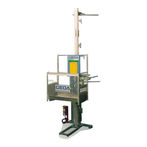
GEDA COMBILIFT 250 Z User manual

B 071 D Ausgabe 03.2000
Assembly and Operating
Instructions
Vertical and
Inclined hoist
For loads
Load capacity vertical 200 kg
Load capacity inclined 250 kg
Year of manufacture:......................
Serial number:..................................
Mertinger Straße 60 •D-86663 Asbach-Bäumenheim
Telephone + 49 (0)9 06 / 98 09-0
Telex + 49 (0)9 06 / 98 09-50
Email: [email protected]
WWW: http://www.geda.de

Vertical and inclined hoist
Assembly and operating instructions page 2 of 52 B 071 U edition 03.2000
serial no.. designation
approx. weight (kg)
2350
for use as a inclined and vertical hoist
104
Load capacity for vertical use 200 kg
Load capacity inclined use 250 kg
Lifting speed 25 m/min
Base unit consisting of:
−Base section 2,0 m
−Trolley with drive unit 1,3 kW/230 V/50 Hz and overspeed safety device
−Plug-in control 5 m
−spring cable reel with trailing cable for 30 m lifting height
−Transport axle
Extension of the base unit
2355 Ladder section 2 m with rack, cable guide and quick lock 22
2356 Ladder section 1 m with rack, cable guide and quick lock 11
Equipment for base unit for vertical use
2360 Load platform (internal dimensions 136 x 75 x 110 cm) 106
2361 Scaffold hold “standard“ 1,7
2369 Scaffold hold “special“ 6,9
2362 Rail tie
(2 sets for base section and 1 set for each 4 m ladder section)
2,1
2365 Set of extension tubes for rail tie
(4 tubes, 4 couplings)
35
2363 Wall tie 7,5
1177 Landing level safety gate (hot-dip galvanised) with mechanically locked sliding door (for all
tubular scaffolds Ø 48 mm, can be adjusted to fit 1.60 - 2.50 m wide scaffold sections)
54
Equipment for base unit for inclined use
Load carrying devices
2893
General purpose platform
with hinged guard rail
33
2817
Bucket hanger
can be attached to the general purpose platform
6,5
2894
Transport platform
with hinged guard rail (platform inclination adjustable)
34
9866
Large transport platform
with three-sided hinged guard rail (platform inclination adjustable)
51
2830
Sheet carrier
with prop, adjustable for sheet widths
0.5 – 1.6 m
40
2860
Tile holder
with hinged guard rail, tile cart and two pallets for roof tiling
40
Accessories
2367
Angle track section
20°
18,5
2368
Angle track extension
10°
3,4
2823
Small building site main cabinet
8
2824
Cable drum
with 33 m cable, 3 x 2.5 mm² (minimum cable cross-section)
7
2804
Extension cable,
20 m, for control
5
2884
Roof tile batten trolley
11
2826
Roof tie
(smoothly adjustable)
10
2366
Aluminium ladder prop 5.7 m
22
2373
Aluminium ladder prop 5.7 m
can be extended (single prop)
11
2829
Aluminium ladder prop extension to 7.2 m

Vertical and inclined hoist
Assembly and operating instructions page 3 of 52 B 071 U edition 03.2000
Contents:
chapter page
1 FOREWORD.................................................................................................................................................................6
2 RATING.........................................................................................................................................................................7
3 PROPER USE AND AREA OF APPLICATION ......................................................................................................8
4 SAFETY.........................................................................................................................................................................9
4.1 E
XPLANATION OF SYMBOLS AND NOTES
......................................................................................................................9
4.1.1 Operational safety symbol ................................................................................................................................9
4.1.2 Attention............................................................................................................................................................9
4.1.3 Note...................................................................................................................................................................9
4.2 G
ENERAL SAFETY
........................................................................................................................................................9
4.3 O
PERATIONAL
S
AFETY
..............................................................................................................................................10
4.3.1 Inspection........................................................................................................................................................11
4.3.2 Safety instructions for assembly, operation and transport .............................................................................11
4.3.3 Safety instructions for maintenance................................................................................................................11
4.4 T
HE IDEA BEHIND JOB SAFETY INSTRUCTIONS
...........................................................................................................12
4.5 E
MPLOYEES MUST BE INSTRUCTED IN
: ......................................................................................................................12
5 TECHNICAL DATA ..................................................................................................................................................13
6 DESCRIPTION ...........................................................................................................................................................14
6.1 C
OMPONENTS AND OPERATING ELEMENTS
................................................................................................................15
6.2 A
CCESSORIES
............................................................................................................................................................17
7 REQUIREMENTS FOR THE PLACE OF ERECTION ........................................................................................18
8 TRANSPORT ..............................................................................................................................................................19
9 ASSEMBLY.................................................................................................................................................................19
9.1 G
ENERAL SAFETY INSTRUCTIONS
..............................................................................................................................19
9.1.1 Special safety instructions for inclined use.....................................................................................................20
9.1.2 Special safety instructions for vertical use......................................................................................................20
9.2 V
ERTICAL ASSEMBLY
................................................................................................................................................20
9.2.1 Anchoring in front of a scaffold ......................................................................................................................21
9.2.2 Anchoring in front of a wall............................................................................................................................21
9.2.3 Erecting and aligning the base unit ................................................................................................................22
9.2.4 Installing the load platform ............................................................................................................................23
9.2.5 Extending the base unit...................................................................................................................................23
9.2.6 Anchoring forces and space requirement .......................................................................................................26
9.3 P
ROTECTION OF LOADING AND UNLOADING POINTS
..................................................................................................29
9.3.1 Securing the landing level safety gate at the scaffold .....................................................................................29
9.3.2 Securing the landing level safety gate to the wall...........................................................................................31
9.4 I
NCLINED ASSEMBLY
.................................................................................................................................................31
9.4.1 Assembly with angle track section ..................................................................................................................32
9.4.2 Using the ladder props....................................................................................................................................33
9.4.3 Roof tie............................................................................................................................................................35
9.5 I
NSTALLING THE LOAD CARRYING DEVICE FOR INCLINED USE
...................................................................................35
9.5.1 General purpose platform...............................................................................................................................36
9.5.2 Bucket hanger (for general purpose platform) ...............................................................................................36
9.5.3 Transport platform..........................................................................................................................................36
9.5.4 Large Transport platform ...............................................................................................................................37
9.5.5 Sheet carrier ...................................................................................................................................................37
9.5.6 Tile holder with cart........................................................................................................................................38

Vertical and inclined hoist
Assembly and operating instructions page 4 of 52 B 071 U edition 03.2000
chapter page
10 OPERATION...............................................................................................................................................................39
10.1 S
AFETY INDICATIONS
...........................................................................................................................................39
10.1.1 Special safety instructions for vertical use......................................................................................................39
10.1.2 Special safety instructions for inclined use.....................................................................................................40
10.2 U
NAUTHORISED MODE OF OPERATION
..................................................................................................................40
10.3 S
AFETY CHECK
.....................................................................................................................................................40
10.4 O
PERATING THE HOIST
.........................................................................................................................................41
10.5 L
OADING AND UNLOADING IN VERTICAL USE
.......................................................................................................41
10.6 S
USPENDING
/
FINISHING WORK
.............................................................................................................................41
10.7 E
MERGENCY SHUT
-
DOWN
.....................................................................................................................................42
11 DISMANTLING..........................................................................................................................................................42
11.1 D
ISMANTLING THE INCLINED HOIST
......................................................................................................................42
11.2 D
ISMANTLING THE VERTICAL HOIST
.....................................................................................................................42
12 CAUSES AND ELIMINATION OF FAULTS .........................................................................................................43
12.1 P
OTENTIAL FAULTS DURING OPERATION
..............................................................................................................43
12.1.1 Power failure or defective motor ....................................................................................................................43
12.1.2 Load platform travelled too low......................................................................................................................44
12.1.3 Load platform travelled too high ....................................................................................................................44
12.2 S
AFETY DEVICE HAS TRIGGERED
..........................................................................................................................44
13 MAINTENANCE ........................................................................................................................................................45
13.1 D
AILY CLEANING
..................................................................................................................................................45
13.2 D
AILY INSPECTION
/
MAINTENANCE
.......................................................................................................................45
13.3 W
EEKLY INSPECTION
/
MAINTENANCE
...................................................................................................................45
13.4 M
ONTHLY INSPECTION
/
SERVICE
..........................................................................................................................45
13.5 Q
UARTERLY INSPECTION
/
SERVICE
........................................................................................................................45
13.6 A
NNUAL INSPECTION
............................................................................................................................................46
13.7 C
HECK THE OVERSPEED SAFETY DEVICE BY MEANS OF A DROP TEST
:...................................................................46
13.8 E
VERY
3000
HOURS OF OPERATION
......................................................................................................................46
14 REPAIRS .....................................................................................................................................................................46
15 DISPOSAL OF THE HOIST .....................................................................................................................................47
16 GUARANTEE .............................................................................................................................................................47
EC DECLARATION OF CONFORMITY ........................................................................................................................48
17 APPENDIX FOR ENTRY OF ANNUAL INSPECTION........................................................................................49
Table of illustrations:
fig. 01 name plate GEDA-Combilift 250 Z ..............................................................................................7
fig. 02 main switch..................................................................................................................................10
fig. 03 EMERGENCY-OFF button ........................................................................................................10
fig. 04 safety instruction..........................................................................................................................11
fig. 05 COMBILIFT 250 Z vertical ........................................................................................................15
fig. 06 COMBILIFT 250 Z inclined .......................................................................................................16
fig. 07 components of the base unit ........................................................................................................17
fig. 08 plug-in control .............................................................................................................................17
fig. 09 scaffold hold “standard” ..............................................................................................................17
fig. 10 scaffold hold “special“.................................................................................................................17
fig. 11 lowering the assembly guard .......................................................................................................19
fig. 12 base enclosure for inclined use ....................................................................................................20

Vertical and inclined hoist
Assembly and operating instructions page 5 of 52 B 071 U edition 03.2000
fig. 13 enclosure for vertical use.............................................................................................................20
fig. 14 anchoring in front of a scaffold ...................................................................................................21
fig. 15 wall tie .........................................................................................................................................21
fig. 16 rail tie...........................................................................................................................................22
fig. 17 anchoring to the base unit............................................................................................................22
fig. 18 raising the trolley for the installation of the load platform..........................................................23
fig. 19 fitting the load platform ...............................................................................................................23
fig. 20 assembling the ladder sections ....................................................................................................24
fig. 21 locking lever ................................................................................................................................24
fig. 22 limit switch activating element....................................................................................................25
fig. 23 erection plan ................................................................................................................................26
fig. 24 anchoring to the wall ...................................................................................................................27
fig. 25 anchoring to the scaffold .............................................................................................................28
fig. 26 landing level safety gate ..............................................................................................................29
fig. 27 transporting the landing level safety gate ....................................................................................29
fig. 28 installing the landing level safety gate ........................................................................................30
fig. 29 aligning the landing level safety gate ..........................................................................................30
fig. 30 opening width of landing level gate ............................................................................................30
fig. 31 wall fixing device for the landing level safety gate.....................................................................31
fig. 32 assembling ladder sections for inclined assembly.......................................................................31
fig. 33 angle track section .......................................................................................................................32
fig. 34 angle track extension ...................................................................................................................32
fig. 35 load table......................................................................................................................................33
fig. 36 scale for the angle of inclination..................................................................................................33
fig. 37 ladder prop...................................................................................................................................33
fig. 38 latching in the single ladder prop ................................................................................................34
fig. 39 latching in the double ladder prop ...............................................................................................34
fig. 40 clamping lever .............................................................................................................................34
fig. 41 setting angle for the ladder props ................................................................................................34
fig. 42 roof tie..........................................................................................................................................35
fig. 43 fixing to the trolley ......................................................................................................................35
fig. 44 general purpose platform .............................................................................................................36
fig. 45 bucket hanger...............................................................................................................................36
fig. 46 assembling the transport platform ...............................................................................................36
fig. 47 transport platform ........................................................................................................................37
fig. 48 large transport platform ...............................................................................................................37
fig. 49 sheet carrier..................................................................................................................................37
fig. 50 limit switch activating bar sheet carrier.......................................................................................38
fig. 51 prop..............................................................................................................................................38
fig. 52 tile holder.....................................................................................................................................38
fig. 53 manual control .............................................................................................................................41
fig. 54 lock of the loading ramp..............................................................................................................41
fig. 55 safety catch ..................................................................................................................................41
fig. 56 lifting guard .................................................................................................................................42
fig. 57 manual brake release lever ..........................................................................................................44
fig. 58 overspeed safety device ...............................................................................................................44

Vertical and inclined hoist
Assembly and operating instructions page 6 of 52 B 071 U edition 03.2000
1Foreword
Who are these assembly and operating instructions intended for?
−Personnel responsible for the assembly and maintenance of the hoist
−Personnel responsible for servicing the hoist (cleaning/maintenance)
What do the assembly and operating instructions contain?
These assembly and operating instructions provide information on
−Proper use
−Residual hazards
−Safety
−Assembly
−Operation
−Trouble-shooting
−Customer service
This assembly and operating manual contains important information that is essential for the safe and
economical operation of the hoist. It has been assumed that the hoist is equipped with all available
options.
You should do the following immediately!
Read this assembly and operating manual thoroughly before assembly and commissioning and
follow all instructions, particularly the safety instructions.
What is not included in this assembly and operating manual?
These assembly and operating instructions are not a repair manual!
You will not find information on how to carry out repairs in these assembly and operating instructions.
Remember the following if reselling the hoist:
If you sell the hoist, be sure to hand over this assembly and operating manual with entries of annual
inspection to the purchaser, together with the list of spare parts.

Vertical and inclined hoist
Assembly and operating instructions page 7 of 52 B 071 U edition 03.2000
2Rating
This operating manual applies to the following model: GEDA-Combilift 250 Z
fig. 01 name plate GEDA-Combilift 250 Z
Manufacturer's address:
Mertinger Straße 60
D-86663 Asbach-Bäumenheim
Telephone + 49 (0)9 06 / 98 09-0
Telex + 49 (0)9 06 / 98 09-50
Email: [email protected]
WWW: http://www.geda.de
CE marking
The GEDA 250 Z carries the CE mark
Country of origin: Made in Germany
When ordering spare parts, please specify:
- Model
- Year of manufacture
- Serial no.
- Operating voltage
- Quantity required
The nameplate is located on the hoist trolley.
NOTE
Spare parts must meet the manufacturer's technical requirements! Only genuine GEDA spare parts
may be used.

Vertical and inclined hoist
Assembly and operating instructions page 8 of 52 B 071 U edition 03.2000
3Proper use and area of application
The GEDA-Combilift 250Z is arack and pinion hoist which is erected
temporarily and is intended exclusively for the transport of goods during
building activities. Any other use, such as, for example, the transport of people
(except for assembly and maintenance purposes), is considered to be an abuse
of the equipment. The manufacturer/supplier accepts no liability for damages
resulting from such use. The risk is borne solely by the user.
•The GEDA hoist may only be used as an assembly hoist for the installation of scaffolds as well as
for the transport of loads (goods) during construction work.
•Operating the hoist as a vertical construction hoist, you have to install one or more landing level
safety gates. Operation of the hoist may only be started after the landing level safety gates have
been installed.
•The hoist may only be used vertically for the assembly of scaffolds.
Proper use of the hoist involves the following:
−Observance of the conditions for assembly, operating and maintenance (assembly and operating
instructions).
−Annual inspections performed by an expert.
−Being aware of foreseeable faulty behaviour of other people.
Improper use of the GEDA Combilift 250 Z may lead to the following
−Danger to life and limb of the user or third parties.
−Damage to the hoist and other property.
Requirements on the assembly personnel
The GEDA 250Z Combilift may only be assembled, operated and serviced by persons who, through
training or practical knowledge, are in a position to handle the equipment properly and who have been
instructed about the dangers involved. These persons must be appointed to the tasks of assembly,
dismantling and maintenance by the employer.
Operating personnel
The hoist may only be operated by personnel who, through their training or practical knowledge, are in
a position to handle the equipment properly. These persons must
•be at least 18 years of age;
•be selected to operate the hoist by the employer;
•have received appropriate instruction and be aware of the relevant hazards.
Residual hazards
Even if all safety measures have been carried out, there are permanent
hazards. Permanent hazards are potential dangers that are easy to overlook,
such as, for example:
−Injuries arising from uncoordinated operation.
−Danger of a fault in the control system.
−Danger when working with the electrical equipment
−Danger due to damage to the load carrying device.
−Danger due to improperly secured load falling.
−Danger due to high wind speeds (> 72 km/h).
−Hazards when entering and leaving the load platform.

Vertical and inclined hoist
Assembly and operating instructions page 9 of 52 B 071 U edition 03.2000
4Safety
4.1 Explanation of symbols and notes
4.1.1 Operational safety symbol
This symbol is found next to every safety instruction where there is a danger of
lethal injury to the operator. Pay attention to these instructions and be careful
when handling the machine!
4.1.2 Attention
ATTENTION This symbol is found wherever particular instructions, regulations or
prohibitions relating to damage prevention are given, in order to prevent damage
to the hoist.
4.1.3 Note
NOTE This symbol is found wherever particular instructions, regulations or prohibitions
relating to damage prevention are given, in order to prevent damage to the hoist.
4.2 General safety
The GEDA Combilift 250Z, hereafter referred to as hoist, has been designed according to state-of-the-
art technology and is safe for operation. However, the nature of the operating procedures is such that
the hoist has areas and parts that cannot be protected without impairing the function and operating
capability. Therefore, good personal safety practice is essential to protect the personnel and the hoist.
The hoist can present dangers if it is used incorrectly by untrained personnel or if it is not used in
accordance with regulations.
•Please read the assembly and operating instructions for the hoist, as well as the safety instructions,
before transportation, assembly, commissioning, dismantling or maintenance, and observe these
instructions carefully!
Read the assembly and operating instructions and make sure
you understand them before working with the machine!
•Keep the operating instructions in an easily accessible place close to the hoist.
•In addition to the assembly and operating instructions, generally applicable conditions as well as
laws concerning accident prevention and environmental protection in the country where the
inclined hoist is being employed also apply (e.g. the wearing of personal protective clothing such
as protective helmets, safety shoes etc.).
•Observe all instruction and warning signs.
•
Only operate the hoist wearing close-fitting clothing, safety
shoes and a safety helmet. Do not wear jewellery, such as
chains and rings. There is the risk of injury due to getting
caught or pulled in.
•If injuries or accidents occur, immediately call a doctor.

Vertical and inclined hoist
Assembly and operating instructions page 10 of 52 B 071 U edition 03.2000
Consequences of non-compliance with the safety instructions
Non-compliance with safety instructions can result in danger to people, the environment and to the
hoist. Non-compliance can also result in the lapsing of any damage compensation claims.
Requirements for operating personnel
See chapter operation
4.3 Operational Safety
•The hoist must be assembled and dismantled in accordance with these assembly instructions under
the direction of a skilled worker appointed by the employer.
•Erect the hoist so that it stands firmly and secure to the ground with ground spikes.
•Comply with the load capacity of the hoist.
•Only use the hoist in technically perfect condition, with awareness of safety and dangers, in
compliance with the operating instructions
•Faults which may compromise operational safety should be removed immediately.
•In the event of any changes in the hoist or its operating behaviour that compromise safety, stop the
hoist immediately and report the fault to the management or the management representative.
•Do not undertake any changes, additions or modifications to the hoist. This also applies for the
fitting and adjustment of safety devices, such as, for example, limit switches.
•Do not change, remove, avoid or bypass the protection facilities.
•Replace damaged or removed instruction and warning signs as well as safety inscriptions.
•If operation is interrupted, switch off the hoist at the main switch and
use the padlock to protect against restarting.
fig. 02 main switch
•In situations that are dangerous to the operating personnel or to the
hoist, the hoist can be stopped by pressing the EMERGENCY OFF
button of the manual control (1).
•In the event of wind speeds of >72 km/h, stop and lower the hoist.
(Wind force 7-8, wind breaks branches off trees and makes walking
very difficult).
fig. 03 EMERGENCY-OFF button
1

Vertical and inclined hoist
Assembly and operating instructions page 11 of 52 B 071 U edition 03.2000
4.3.1 Inspection
The hoist is subject to the EC machine guideline. A declaration of conformity is printed in these
operating and assembly instructions.
Regular inspections:
•Have the hoist inspected by an expert in accordance with the conditions of use, as required, but at
least once a year.
•Record the results of the annual expert inspection in the appendix.
The following groups of people are examples of those considered competent to carry out the annual
inspection:
-
Operational engineers,
-
Machinists,
-
Specially trained technical personnel,
-
GEDA customer service installation engineers.
Experts are people who, due to their specialist training and experience, have sufficient knowledge in
the field of this equipment and are so familiar with the relevant government health and safety
standards, accident prevention regulations, guidelines and generally acknowledged technical standards
(e. g. EN standards), that they are able to assess the safe operating condition of building hoists.
4.3.2 Safety instructions for assembly, operation and transport
•Before beginning work, familiarise yourself with the working environment at the place of
deployment, e.g. obstacles in the working and transportation areas, the bearing capacity of the
ground and the necessary protection of the building site from the public area.
•Only load and transport the hoist when it has been carefully dismantled, packed and secured.
•On principle, always protect the hoist against unauthorised use (disconnect)!
•Loads must be placed securely on the load platform, and materials that
tend to slip, that are higher than the load platform, or that could fall
over, must be secured (also bear in mind winds that may suddenly
occur).
•Do not stand or work below the load platform!
•Do not put any objects beneath the load platform.
•Load the platform centrally, and observe the maximum load capacity.
fig. 04 safety instruction
•Check for visible damages and faults at least once a day. Report any detected changes or faults to
the management or a management representative immediately. If necessary, stop the hoist at once
and make safe.
4.3.3 Safety instructions for maintenance
•Pull out mains supply plug before carrying out any maintenance work.
•Only allow authorised experts to carry out maintenance and repair work. The particular dangers
involved in working on electrical systems, for example, must also be noted during such tasks.
•Upon completion of maintenance tasks, correctly replace all protective devices that have been
removed.
•Unauthorised modifications or changes to the hoist impair safety and are not permitted.

Vertical and inclined hoist
Assembly and operating instructions page 12 of 52 B 071 U edition 03.2000
•Spare parts must meet the manufacturer's technical requirements. We recommend to use only
genuine GEDA spare parts.
4.4 The idea behind job safety instructions
Job safety instructions are rules provided by the employer for safe operation. These are binding
instructions, which the employer issues within the scope of his management role. The employees are
obliged by the accident prevention regulations to follow these instructions.
The employer is, as stipulated by the accident prevention regulation "General regulations", obliged to
create and provide job safety instructions.
According to this regulation, the employer must meet certain requirements concerning accident
prevention and give instruction to those insured on the potential dangers involved in their line of work,
as well as the measures required to prevent them. The employer can fulfil these requirements by
providing operating instructions.
The operating instructions provided here should therefore be expanded on by national regulations for
accident prevention as well as environment protection regulations!
e.g.: EC guideline 89/655/EEC regarding minimum requirements for safety and health protection for
employees using operating equipment in their work.
4.5 Employees must be instructed in:
-
The dangers arising from working with the load carrying devices deployed and the required safety
procedures and rules of danger and first aid.
-
Type and scope of regular inspection for safe working conditions.
-
Maintenance.
-
Removal of operational faults.
-
Environmental protection.
-
Safe handling of the electrical equipment.
•The firm using the hoist must ensure cleanliness and tidiness, by means of instructions and
inspections, at the site where the hoist is erected.
•The areas of responsibility for assembly, dismantling, operation and maintenance must be clearly
set out by the user firm and observed by all employees, so that no areas of competence concerning
safety are unclear.
•The operator must undertake only to operate the hoist in perfect condition. He is obliged to
immediately report to his superior any changes to the hoist that concern safety.
•Observe all instruction and warning signs.
•The operator must also ensure that no unauthorised persons linger on the hoist.

Vertical and inclined hoist
Assembly and operating instructions page 13 of 52 B 071 U edition 03.2000
5Technical Data
-
Weight of the base unit: 104 kg
-
Length of the base unit (extension option): 2,1 m
-
Lifting speed: 25 m/min.
-
Trigger speed of the safety device: ca. 30 m/min.
-
Drive torque: 350 kg
-
Length of one ladder section: 1m / 2m
-
Weight of one ladder section (2m): 22 kg
-
Noise emission values (the measuring uncertainty
constant is 4 dB (A))
L
PA
< 85 dB (A)
Vertical assembly
-
Load capacity: 200 kg
-
Max. erection height: 32 m
-
Max. projecting ladder length during assembly: 3,5 m
-
Max. projecting ladder length in operation: 2 m
-
Fixing distance: 4 m
-
Anchoring forces: See chapter 9.2.6
-
Dynamic pressure:
during assembly
operational
non-operational
q = 100 N/m² (= 45 km/h)
q = 250 N/m² (= 72 km/h)
prEN12158-1 (platform on the
ground)
Inclined assembly
-
Load capacity: 250 kg
-
Max. erection height (up to eaves): 19 m

Vertical and inclined hoist
Assembly and operating instructions page 14 of 52 B 071 U edition 03.2000
6Description
The GEDA-COMBILIFT 250 Z is a vertical and inclined hoist for scaffold constructors and
construction workers. It can be used vertically or inclined.
•The hoist can be vertically erected up to a height of 32m.
•As an inclined hoist, it can be erected up to a length of 19m. When supported on the roof, the hoist
can be extended up to a maximum of 32 m.
•The maximum lifting speed is 25 m/min.
•Assembly is carried out directly on the building site.
•The light and handy aluminium rails are fitted into each other and bolted at the top rung with the
ladder lock.
•The hoist switches off automatically when the trolley arrives at the top or bottom, or if the access
ramp is opened, the assembly guard is lowered or the safety device has triggered.
•The hoist is operated with the plug-in manual control.
•Various load carrying devices (see page 2)

Vertical and inclined hoist
Assembly and operating instructions page 15 of 52 B 071 U edition 03.2000
6.1 Components and operating elements
fig. 05 COMBILIFT 250 Z vertical
1 base unit with base section 5 door 9 wall tie
2 transport axle 6 access ramp 10 landing level safety gate
3 spring cable reel 7 assembly guard 11 ladder section
4 load platform 8 rail tie 12 ladder lock
1
2
3
4
6
5
7
8
9
10
11
12

Vertical and inclined hoist
Assembly and operating instructions page 16 of 52 B 071 U edition 03.2000
fig. 06 COMBILIFT 250 Z inclined
1 base unit with base section 5 ladder section
2 transport axle 6 ladder lock
3 spring cable reel 7 angle track section
4 load carrying device
1
2
3
4
5
6
7

Vertical and inclined hoist
Assembly and operating instructions page 17 of 52 B 071 U edition 03.2000
1Main switch
2Socket (5 pin) for control
3Trolley
4Mains supply with plug
5Wheels for transport
6Plug-in control
fig. 07 components of the base unit
1 EMERGENCY OFF button
2 UP button
3 DOWN button
4 Control section
5 Plug, 5-pin.
6 Suspension clamp
fig. 08 plug-in control
6.2 Accessories
There are two different models of scaffold holds for the transport of parts of the scaffold on the
platform.
Scaffold hold “standard“
For secure transport of scaffold tubes on the platform.
•The scaffold hold (1) has to be fixed to the platform with screws.
fig. 09 scaffold hold “standard”
Scaffold hold “special“
For the secure transport of scaffold tubes
and scaffold sections.
•Screw the hold for the ground tube (3)
to the floor plate of the load platform
•The scaffold hold (2) can be unfolded
to the top.
fig. 10 scaffold hold “special“
1
2
3
5
6
4
3
2
1
5
4
3
2
1
6

Vertical and inclined hoist
Assembly and operating instructions page 18 of 52 B 071 U edition 03.2000
7Requirements for the place of erection
Ground conditions
•Horizontal, load-bearing ground.
•If this is not available use load-distributing support parts.
Foundation pressure
Useful load of the hoist 200 kg (D)
Weight of one ladder 22 kg (A)
Length of one ladder 2,0 m
Height of the base unit 2,0 m
Empty load of the platform 220 kg (B)
Floor space without load-distributing
support parts(shoe for the ladder)
0,022 m² (C1)
Floor space with load-distributing
support parts
(e.g. with a 20cm x 70cm board)
0,140 m² (C2)
Erection height in m
6 10 14 18 22 26 30 32
Number of necessary ladders (E) 2 4 6 8 10 12 14 15
Total weight of the ladders (kg) (F=AxE) 44 88 132 176 220 264 308 330
Total weight (kg) (G=B+D+F) 464 508 552 596 640 684 728 750
Foundation pressure without load-
distributing support devices
(kN/m²)
(H=G/C1) 211 231 251 271 291 311 331 341
Foundation pressure with load
distributing support devices
(kN/m²)
(H=G/C2) 33 36 39 43 46 49 52 54
Electrical power supply (on site)
•A building site mains cabinet is required on site with a safety switch with 230 V 50 Hz and 16 A
slow-blow fuse (cf. VDE 0100 section 704).
•For the mains supply line, use a 3x2.5 mm2(max. 50m) sheathed flexible cable and lead it directly
to the building site mains cabinet without connecting other current consumers in between, in order
to avoid voltage drop and consequent loss of power of the motor.
NOTE
If the power supply is unsatisfactory, disconnect other current consumers.
•Connect the manual control to the plug on the base section and the mains plug to the on-site power
supply. - The hoist is ready for operation again.

Vertical and inclined hoist
Assembly and operating instructions page 19 of 52 B 071 U edition 03.2000
8Transport
•Check whether the consignment has suffered damages during transportation and that it complies
fully with your order.
•Should damages occur during transport, the haulier and the dealer should be notified at once!
•The hoist can be dismantled into components form for convenient transport around the building
site.
-
Heaviest component = 104 kg
-
Longest section = 2,2 m
ATTENTION
In order to transport the load platform with open vehicles,
the assembly guard has to be lowered.
•Lift the bracket (2) of the assembly guard slightly and lower
the platform past the guidances.
fig. 11 lowering the assembly guard
9Assembly
The hoist must be assembled in accordance with the assembly and operating
manual, under the direction of a skilled person appointed by the employer!
This skilled worker must be familiar with the assembly and operating
instructions, possess adequate experience and be aware of the dangers involved
in handling the hoist.
Requirements on the assembly personnel
The machine may only be assembled, operated and serviced by skilled personnel (experts) who,
through their training or practical knowledge, are in a position to handle the equipment properly, and
who are aware of the relevant hazards. The employer must appoint these people for assembly,
dismantling and maintenance work.
9.1 General safety instructions
•Prior to each assembly, make sure that that all parts of the hoist, such as, for example, ladder
sections with racks, electric cables and control are in perfect condition. If any of the components
have been damaged, do not operate the hoist! – Replace damaged parts immediately.
•Familiarise yourself with the working environment at the place of erection, e.g. obstacles in the
working and transportation areas, the load bearing capacity of the ground and the protection of the
building site with fences to render the area safe for public access.
•The operator has to take care that the danger zone of the lower loading point, with the exception of
the access to the platform, is blocked off (fig. 12 and 13).
•The operator has to make sure that the access to the lower loading point is secured if there is
danger of loads falling down.
•No one must stay below the hoist.
•Comply with the national accident prevention regulations of the health and safety authorities and
all valid laws and guidelines.
•Always wear protective clothing (e.g. protective helmet, safety shoes).
1
2

Vertical and inclined hoist
Assembly and operating instructions page 20 of 52 B 071 U edition 03.2000
9.1.1 Special safety instructions for inclined use
•Block off the danger area of the hoist.
•Do not exceed the maximum hoist assembly length of
19 metres between ground level and eaves height! –
When supported on the roof, the hoist can be extended
to a ladder length of up to 32 m.
•Comply with the load capacity of the hoist. It is
determined by the length of the hoist, the angle of
inclination of the ladder and whether the ladder prop
is being used or not. Refer to the scale of inclination
as well as the table of loads on the ladder prop.
•The transport of people is strictly prohibited.
•For the assembly please observe the instructions in
chapter 9.4.
fig. 12 base enclosure for inclined use
9.1.2 Special safety instructions for vertical use
•For vertical hoists, the enclosure (1) must be at least
0.5 m distant from moving parts.
•Being used for the assembly of scaffolds, the
assembly of the hoist itself continues. In this case
landing level safety gates or the base enclosure may
be installed later. In any case protective devices have
to be always installed in order to prevent people from
falling.
•The transport of people is forbidden!
•For the assembly please observe the instructions given
in chapter 9.2.
fig. 13 enclosure for vertical use
•Landing level safety gates have to be installed at loading points at a height of 2 metres or more in
order to prevent people from falling.
•During assembly, the projecting ladder sections may be travelled to a maximum of 3.5 m beyond
the last anchoring point! (Upper edge of trolley to rail tie)
•Make sure that the masonry can take the anchoring forces. A building expert must check if the wall
of the building is suitable for such anchoring forces. This will also dictate whether dowels or
through bolts must be used.
9.2 Vertical assembly
The hoist can be assembled very simply from the load platform. However, the following should be
noted:
•The wind speed during assembly must not exceed 45 km/h (12.5 m/sec.)
•The load platform is also provided for assembly. The assembly guard in front of the ladder sections
can be lowered (the control is interrupted then).
•Use the safety guard at the front (close clamp above the ramp).
•Control may only be carried out from the platform (use the extension cable serial no. 2804 for the
control).
•Install the first anchoring device at a height of approximately 1.8m (at the scaffold below the
covering floor).
Measurements in
metres
Measurements in
metres
1
Table of contents
Other GEDA Lifting System manuals
Popular Lifting System manuals by other brands

Wealden Rehab
Wealden Rehab GoLift Installation guidance

Tuxedo
Tuxedo FP8K-DS Installation & operation manual

Allegri
Allegri PRATIK 30 Use and maintenance manual

Challenger Lifts
Challenger Lifts E12 Installation, operation & maintenance manual

Hunter
Hunter L494HD Operation manual

Lippert Components
Lippert Components Level-Up Installation and owner's manual