artisan WIENER Mini Crate 475 User manual

-~
ARTISAN
®
~I
TECHNOLOGY
GROUP
Your definitive source
for
quality
pre-owned
equipment.
Artisan Technology
Group
Full-service,
independent
repair
center
with
experienced
engineers
and
technicians
on staff.
We
buy
your
excess,
underutilized,
and
idle
equipment
along
with
credit
for
buybacks
and
trade-ins
.
Custom
engineering
so
your
equipment
works
exactly as
you
specify.
•
Critical
and
expedited
services
•
Leasing
/
Rentals/
Demos
• In
stock/
Ready-to-ship
•
!TAR-certified
secure
asset
solutions
Expert
team
ITrust
guarantee
I
100%
satisfaction
All
tr
ademarks,
br
a
nd
names, a
nd
br
a
nd
s a
pp
earing here
in
are
th
e property of
th
e
ir
r
es
pecti
ve
ow
ner
s.
Visit our website - Click HERE

WIENER Mini Crate 475
User Manual


12/11/2017 i WIENER_475mini.v1.0
General Remarks
The only purpose of this manual is a description of the product. It must not be interpreted as a declaration
of conformity for this product including the product and software.
W-Ie-Ne-R revises this product and manual without notice. Differences between the description in
manual and the product are possible.
W-Ie-Ne-R excludes completely any liability for loss of profits, loss of business, loss of use or data,
interrupt of business, or for indirect, special incidental, or consequential damages of any kind, even if W-
Ie-Ne-R has been advises of the possibility of such damages arising from any defect or error in this
manual or product.
Any use of the product which may influence health of human beings requires the express written
permission of W-Ie-Ne-R.
Products mentioned in this manual are mentioned for identification purposes only. Product names
appearing in this manual may or may not be registered trademarks or copyrights of their respective
companies.
No part of this product, including the product and the software may be reproduced, transmitted,
transcribed, stored in a retrieval system, or translated into any language in any form by any means without
the express written permission of W-Ie-Ne-R.
Mains Voltage and Connection
The Power supplies are equipped with a “World”- mains input, which works properly form 94VAC up to
264VAC and within a frequency range of 47 to 63Hz. Before connecting to the mains please double-
check correspondence.
Safety
After connecting the chassis to the mains and switching the AC MAINS on, the auxiliary power supply
module is powered permanently.
Do not open or work inside the power box area without first disconnecting the unit from AC mains.
Cooling
VME Mini Crates are equipped with temperature probes to protect the unit against severe damages. It
cannot be guaranteed that inserted modules are protected sufficient in the same way if
1. The fan speed is reduced to lower or minimum speed
2. The air ingress or/and outlet holes are blocked

12/11/2017 ii WIENER_475mini.v1.0
Table of contents:
1 General Information............................................................................................................................. 3
1.1 475 Mini Crate Series Features .................................................................................................... 3
1.2 Front and Rear Side View ............................................................................................................ 4
1.3 Cooling......................................................................................................................................... 5
1.4 Power Supply ............................................................................................................................... 5
1.5 Display and CML00 Shelf Manager............................................................................................. 5
1.5.1 CML DC ON/OFF Switch and Status LED ......................................................................... 6
1.5.2 Ethernet Connector............................................................................................................... 6
1.5.3 USB Connector..................................................................................................................... 7
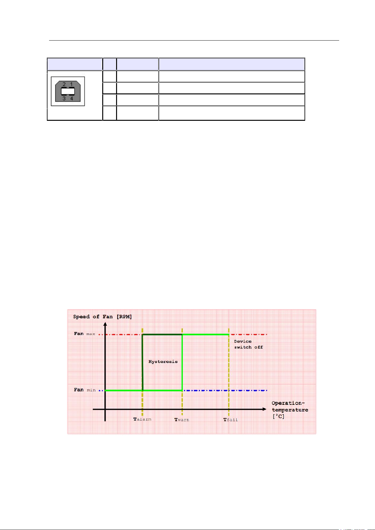
1.5.4 CML Temperature Sensor Inputs / Fan Control................................................................... 7
1.6 Ordering Information ................................................................................................................... 9
2 WIENER 475 Mini Chassis Operation............................................................................................... 10
2.1 Main operation modes and associated submenus....................................................................... 11
2.2 Front Panel LED’s...................................................................................................................... 13
3 Ethernet Remote Monitoring and Control.......................................................................................... 14
3.1 SNMP communication protocol................................................................................................. 14
3.2 SNMP Control Examples........................................................................................................... 20
3.3 Setting of IP Addresses via SNMP............................................................................................. 21
3.4 Change of Community Names / Setting of Passwords............................................................... 21
3.5 SNMP Version 3 20
3.6 WIENER SYScontrol Software ................................................................................................ 22
3.6.1 Installation SYScontrol ...................................................................................................... 28
3.6.2 Setting Preferences / IP Address and Crate Scan............................................................... 28
3.6.3 The SYScontrol Main Window.......................................................................................... 29
3.6.4 SYScontrol - Outputs ......................................................................................................... 30
3.6.5 SYScontrol –Fans.............................................................................................................. 31
3.6.6 SYScontrol –Temperature Sensors.................................................................................... 32
3.6.7 SYScontrol Networks tab................................................................................................... 32
3.7 MIB Browser.............................................................................................................................. 33
4 Technical Details VME / VME64x / cPCI Mini crate 475................................................................. 35
5 CML Firmware Update Instructions .................................................................................................. 36

User’s Manual
475 Mini Crate Series
W-Ie–Ne-R
Plein & Baus GmbH
12/11/2017 3
1 General Information
The WIENER 475 mini crate series represents a compact but modular designed 7 slot
VME/VME64x/cPCI chassis with hot-swappable, redundant power supplies. A front-side-plug high
performance DC fan is used for cooling with front to rear air flow.
The front side 6U x 1600 mm card cage is recessed . The 475 crate series is also outfitted with a rear
side 6U x 80mm transition card cage. All chassis parts are compliant to the IEEE 1101.10 standard
with enhanced EMC / ESD.
One or two redundant operating plug-in 250W cPCI power supplies provide sufficient power for all
applications. The CML shelf manager allows full remote monitoring and control of power supply, fan
and chassis.
The WIENER 475 mini crate can be used on the desk either as a desktop or up-right unit or be
installed in a 19” rack.
1.1 475 Mini Crate Series Features
MINI-Bin mechanics for 6Ux160mm modules, suitable either for 19" rack, as a tower- or a
desktop box
IEEE 1101.10 compliant mechanics with enhanced EMC / ESD
7 slot monolithic VME, VME64x (optional P0 connectors) or cPCI backplane
Free rear access for 6U transition modules, standard transition cage for 6U 80mm modules,
provisions for 160 and 120mm foreseen. Special depth on request
Alphanumeric high-visibility LED display for voltages, currents, fan speed, temperatures and
settings / programming, 1 status LED
WIENER CML Shelf Manager for local and remote monitoring and control, monitors and
controls power supply, fan, remote on/off, SYSRES, thermal monitoring, user I/O
programming, with Ethernet and USB interfaces, rear side plugged in
2 Side mounted, removable DC blowers, adjustable speed (1200 … 3200 RPM), temperature
controlled
Programmable under / over voltage and over current trip points, active DC output discharge
Outfitted with one or two 250W cPCI power supplies, plugged in from front, hot swappable,
redundant operation, CE-conformity, 300W power supplies on request
100V –240V world-wide auto-range AC input, with power factor correction, CE-conformity
Dimensions: 19” (482mm) x 5U (215mm) x 417mm [whd], weight: ca. 20 kg

User’s Manual
475 Mini Crate Series
W-Ie–Ne-R
Plein & Baus GmbH
12/11/2017 4
1.2 Front and Rear Side View
Fig. 1.2: Front side view of VME475x_2 chassis
Fig. 1.3: Rear side view of VME 475x_2 chassis
CML
(Ethernet,
USB ports
cPCI power supplies
AC input, IEC 13
with 2 fuses
Main air outlet
(side/rear)
Alphanumeric
display,
ON/OFF,
MODE
Status LED
Air inlet and
DC fan
7 slot VME64x
card cage,
6U x 160mm
Rear side
transition
card cage,
6U x 80mm

User’s Manual
475 Mini Crate Series
W-Ie–Ne-R
Plein & Baus GmbH
12/11/2017 5
1.3 Cooling
The 475 mini crate provides a side-to-side ( optional front-to-side or front-to-rear ) cooling air flow.
The fan tray is field removable.
Using a standard DC fan in push mode a high airflow and static back pressure is achieved. The
maximum fan speed is 3000rpm and can be reduced stepwise via front panel switch operation or
remote control to 1200rpm. The fan operation can be temperature controlled in case the 475 chassis is
outfitted with optional temperature probes. The fan speed is monitored and a fan fail circuit will shut
down power in case of failures.
1.4 Power Supply
The 475 mini crate is outfitted with either one or two cPCI-type 250W power supplies. Optionally
also 300W power supply versions are available. The power supplies are hot-swappable and can
operate in a redundant mode. No minimum load is required. The following table provides the output
current rating for the 250W power supply.
Voltage
Minimum
Typical
Max
Peak.
5V
0A
25A
33A
33A
3.3V
0A
18A
33A
33A
+12V
0A
5A
5.5A
6A
-12V
0A
0.5A
1A
1.5A
Notes: 1.Peak load less than 60sec. with duty cycle <10%.
2.Max. load is the continuous operating load of each rail. But the max. load of each rail can't
be drawn from all outputs at the same time.
Using a special internal power backplane additional filtering and current measurement is provided.
This internal board is also outfitted with crow bars for an active discharge on all DC lines in error
conditions and when powering down.
With the help of the CML Over Voltage (OV), Under Voltage (UV) and Over Current (OC) trip
points can be defined.
1.5 Display and CML00 Shelf Manager
For local and remote monitoring and control the 475 mini crate is outfitted with a CML00 shelf
manager and a high visibility alphanumeric display. In addition to the display of voltages / currents,
temperatures, fan speed and networking it is possible to program most of the chassis and power
supply settings using the front panel switches (see paragraph 2).
The CML00 allows full remote monitoring and control of power supply, fan and chassis parameters
via Ethernet (SNMP v2 and WWW) and offers the following features:
Remote or local switch ON/OFF

User’s Manual
475 Mini Crate Series
W-Ie–Ne-R
Plein & Baus GmbH
12/11/2017 6
Multicolored status LED
12 bit DC Voltage measurement: 4 channels for 3.3V, 5V, 12V and -12V
Temperature measurement: 1-wire-bus for digital temperature sensors
Fan Control: DC fan monitored, fan speed settable, temperature controllable
Fully controlled, programmable trip thresholds (min./max. Voltage & temperature)
Detection of VME RESET and SYSFAIL, generation of VME RESET and ACFAIL,
Detection of Derating or Failure signals from cPCI Power Supplies
Capable to switch cPCI Power Supplies (ON/OFF)
Ethernet connection IEEE 802.3 10BASE-T and IEEE 802.3u 100BASE-TX
WWW-Server integrated, full control via SNMP protocol v.2
PC-Control (connected to galvanic isolated USB) with free available software
IP address settable to a fix value or configurable via DHCP (default)
Firmware update possible via USB or Ethernet.
Automatic data logging on Windows/Linux computer possible
Digital Signal Processor (DSP) for real-time processing of all measured data
Powered by 5V bus voltage and independent power supply
Configuration permanently saved in EEPROM
1.5.1 CML DC ON/OFF Switch and Status LED
The CML is outfitted with a DC Power Switch which is used to switch the system power supply on
(push the switch to the “ON” position) or off (push the switch to the “OFF” position.
The multi-colored Status LED shows the global status of the system:
YELLOW Standby state (the system power supply is off)
GREEN System power is on, all measurement values are in limit
RED System switched off because of any failure
1.5.2 Ethernet Connector
RJ45 Socket
Pin
Signal
Comment
1
TX+
2
TX-
3
RX+
4
GND 1
5
GND 1
6
RX-
7
GND 2
8
GND 2
This is the standard NIC configuration. You need a 1:1-cable to connect a to a HUB, or a cross-over
cable to connect to another NIC (e.g. a computer). There is no automatic signal crossing like with
some routers.

User’s Manual
475 Mini Crate Series
W-Ie–Ne-R
Plein & Baus GmbH
12/11/2017 7
1.5.3 USB Connector
USB Socket
Pin
Signal
Comment
1
VCC
2
D-
3
D+
4
GND
This is the standard USB connector type B. The USB connection is galvanic isolated from the system
to prevent ground loops.
1.5.4 CML Temperature Sensor Inputs / Fan Control
The CML00 can be connected to 8 or more temperature sensors via a 1-wire bus. In the event of an
error, the status LED on the front panel will turned red.
The temperatures can be read with the SNMP network command (crate.sensor.sensorTemperature
OID).
Each temperature is compared with three threshold values (crate.sensor.sensorWarningThreshold,
crate.sensor.sensorAlarmThreshold and crate.sensor.sensorFailureThreshold OIDs).
Two different modes can be set. Please read more about the hysteresis control mode and the linear
control mode in the following paragraph.
To operate the device in the hysteresis control mode, it is necessary to swap the alarm with the
warning temperature value. The alarm temperature has to be less than the warning temperature. The
fan speed executes a hysteresis between the two temperature points of any connected sensor between
maximum speed and the nominal and minimal speed respectively .
If the sensorFailureThreshold of any connected sensor is reached, the main power supply of the
system is switched off.
The controlling result of fan speed is pictured in figure 1.6.
Figure 1.6: Hysteresis control mode

User’s Manual
475 Mini Crate Series
W-Ie–Ne-R
Plein & Baus GmbH
12/11/2017 8
The second mode is the linear control mode. If the temperature of any connected sensor is under the
warning threshold the fans will operate in their nominal and minimum speed respectively.
If the sensorWarningThreshold is reached, all fans will rotate in a calculated linear temperature-
sensitive speed. Overstepping the sensorAlarmThreshold they will switch to their maximum speed.
After exceeding the sensorFailureThrehold of any connected sensor, the main power supply of the
system is switched off.
The controlling result of fan speed is pictured in figure 1.7.
Figure 1.7: Linear control mode
When using the linear control mode it is important to know that there exists a sub mode called low
noise mode. When the nominal speed set by user is under the allowed minimal speed, the device will
switch off all fans. If is it not necessary to cool down the device the fans stand still. After reaching of
sensorwarningThreshold the behavior of fan control is equal to the linear control mode.
The controlling result of fan speed is pictured in figure 1.8.

User’s Manual
475 Mini Crate Series
W-Ie–Ne-R
Plein & Baus GmbH
12/11/2017 9
Figure 1.8: Low noise control mode
1.6 Ordering Information
VME / VME64 Crate Version
Backplane
+5V
+12V
-12V
VME 475_1
VME/VME64
33A
6A
1A
VME 475_2
VME/VME64
66A
12A
2A
VME64x Crate Version
Backplane
+5V
+3.3V
+12V
-12V
VME 475x_1
J1/J2 VME64x
33A
33A
6A
1A
VME 475x_2
J1/J2 VME64x
66A
66A
12A
2A
VME 475x_1_P0
J1/J0/J2 VME64x
33A
33A
6A
1A
VME 475x_2_P0
J1/J0/J2 VME64x
66A
66A
12A
2A
cPCI Crate Version
Backplane
+5V
+3.3V
+12V
-12V
PCI 475_1
6U cPCI
33A
33A
6A
1A
PCI 475_2
6U cPCI
66A
66A
12A
2A

User’s Manual
475 Mini Crate Series
W-Ie–Ne-R
Plein & Baus GmbH
12/11/2017 10
2 WIENER 475 Mini Chassis Operation
Switch on the AC Mains switch located at the power connector on the rear side.
To power the chassis on either the DC ON/OFF switch on the CML00 (rear side) or the “Power” on
the front display can be used on by pushing the switch up.
The main operation modes can be selected by pushing the “Mode Select” switch up or down.
Many main operation modes do have one or more submenus, which can be accessed by the following
special procedure.
You will use the following switches of the 475 mini chassis front panel:
Symbol
Description
Remarks
P▲
Push “Power” switch up (ON)
Main operation mode:
Switch the crate on.
Submenu:
OK button. Used to enter the selected
submenu, request to change a value,
accept the changes.
P▼
Push “Power” switch down
(OFF)
Main operation mode:
Switch the crate off.
Submenu:
CANCEL button. Used to leave a submenu,
discard the changes.
M▲
Push “Mode Select” switch up
Main operation mode:
Select the next operation mode.
Submenu:
Change the selected item to the next
possible state.
M▼
Push “Mode Select” switch
down
Main operation mode:
Select the previous operation mode.
Submenu:
Change the selected item to the previous
possible state.
The following example describes the detailed steps to change the IP gateway address of the fan tray.
Description
Switch
Display
( when 2 lines: display alternating
marked blue: flashing
switch the crate on
P▲
+5V 5.01V 1.2A

User’s Manual
475 Mini Crate Series
W-Ie–Ne-R
Plein & Baus GmbH
12/11/2017 11
select the requested main
operation mode
M▲ or M▼ (until right
mode is displayed)
TCPIP: no link
enter submenu
M▲(push and hold), P▲
Config: Wait
hold both switches up
Config: Wait...
after 4 seconds you can
Config: Ready !
release the switches
TCPIP Address
192.168.91.80
Select submenu “TCPIP
Gateway”
M▲ or M▼ (until right
menu is displayed)
TCPIP Gateway
192.168.91.94
Enter this menu
P▲
192.168.91.94
Change the value
M▲ or M▼
196.168.91.94
Accept change, to next
item
P▲
196.168.91.94
Accept change, to next
item
P▲
196.168.91.94
Accept change, to next
item
P▲
196.168.91.94
Ready, back to submenu
selection
P▲
TCPIP Gateway
196.168.91.94
Ready, leave submenu
M▼
TCPIP: no link
2.1 Main operation modes and associated submenus
Operation
Mode
Submenu
Display
Display voltage and current of the selected output channel
+5V0 5.01V 2.41A
Change of the over current switch-off threshold
+5V0 IOff 60.A
Change of the under voltage switch-off threshold
+5V0 Umin 4.50V
Change of the over voltage switch-off threshold
+5V0 Umax 5.50V
Display the total power at the load
Power 10W
Auto Power Setting (Yes / No)
Auto PowerOn: Yes
SwitchOff (Normal / Delay)
SwitchOff: Normal
ScreenSaver (On / Off)
ScreenSaver: Off

User’s Manual
475 Mini Crate Series
W-Ie–Ne-R
Plein & Baus GmbH
12/11/2017 12
Display the TCP/IP connection state
Possible values & symbols are:
no link (no cable connected)
10M (connected to 10M network)
100M (connected to 100M network)
HD (half duplex)
FD (full duplex)
↓, ↑, ↕ (Frame received, transmitted, both)
Ethernet 100M FD
Change the TCP/IP address (0.0.0.0.0 = DHCP)
TCPIP Address
0.0.0.0
Show Assigned IP address
Assigned IP Add.
192.168.91.80
Change the TCP/IP subnet mask
TCPIP SubnetMask
255.255.255.224
Change the TCP/IP gateway address
TCPIP Gateway
192.168.91.94
Change Boot Option
ALL/BOOTP/DHCP
Allow writes (e.g. switch on/off) via the web server
HTTP:read/write
Change TCP/IP negotiation settings
TCPIPnegotiation
AutoNegotiation
Display of the Ethernet hardware address (MAC).
This address is written at the type plate, too.
TCPIP MAC Addres
0050-C22D-C231
Change the TCP/IP port of the web server
HTTP Port 80
Change the TCP/IP port of the TELNET server
TELNET Port 23
Change the TCP/IP port of the SNMP server
SNMP Port 161
Restore the default SNMP settings (community
strings)
SNMP Default No
Display the fan rotation speed
FANS: 2400 RPM
Change the time for which the fans will continue
running after switching the power supply off.
60s (default)
Display the number of supervised fans
1
Display the fan operating time (hours)
FanTime: xxx.x h
Display Fan Operation Mode
FAN MOD linear
Display the BIN sensor temperature (1 to 8)
Bin TempX: xxºC

User’s Manual
475 Mini Crate Series
W-Ie–Ne-R
Plein & Baus GmbH
12/11/2017 13
Change the WARNIG threshold temperature (fans
will switch to full speed)
Change the ERROR threshold temperature (power
supply is switched off)
Change the FAIL threshold temperature (power
supply is switched off)
2.2 Front Panel LED’s
AC POWER
green large LED if POWER is on
STATUS
green LED if all voltages are within the limit
FAN FAIL
yellow LED if a fan failure is recognized
OVERHEAT
yellow LED if an overheat in the power supply occurs
SYS FAIL
red LED if VME-bus system generates the SYSFAIL
signal (system failure)
FAN SPEED
Red LED if fan speed below 100%

User’s Manual
475 Mini Crate Series
W-Ie–Ne-R
Plein & Baus GmbH
12/11/2017 14
3 Ethernet Remote Monitoring and Control
All WIENER crates with Ethernet ports allow simple monitoring and control via a web browser which
shows status as well as all supply voltages, fan speed and temperatures. It is possible to switch the
crate on or off, send a system Reset (VME: SYSRES) and change the fan speed within the web
browser window. All active controls as on/off and change fan speed will require a user name and
password. The user name is “private” and default password also “private” (can be changed via
SNMP).
The network configuration as IP address (0.0.0.0 default = DHCP), net mask and ports can be
changed via the front panel display and switches or via SNMP.
For full control of crate and power supply parameters or to implement the crate into a slow control
system WIENER is providing a SNMPv2c (Simple Network Management Protocol) compliant
protocol. We suggest NetSNMP as an open source SNMP program which will be used in the further
description. Please see http://net-snmp.sourceforge.net/ for more details.
3.1 SNMP communication protocol
Please download and install netSNMP (32-bit version!!! can be downloaded from file.wiener-d.com)
on the control computer. In order to perform SNMP calls from any WIENER product the WIENER-
CRATE-MIB.TXT file must be stored somewhere on the PC doing the calls, by default that location
should be /usr/share/snmp/mibs (Windows: C:\usr\share\snmp\mibs). The most commonly used
netsnmp calls are:
snmpwalk –returns groups of parameters / items
snmpget –returns a specific parameter (read)
snmpset –sets a specific parameter (write)

User’s Manual
475 Mini Crate Series
W-Ie–Ne-R
Plein & Baus GmbH
12/11/2017 15
Please see the Net-snmp description and help files for detailed instructions and options. All
parameters defined for the WIENER crates and other power supplies are contained within the
WIENER-CRATE-MIB.txt file.
A fast an easy way to begin using SNMP is to use command line arguments. The command line
arguments specified in this document are based on netSNMP. The command line syntax is the same
for both windows and Linux (and MAC OSX).
For all WIENER-CRATE-MIB library calls a quick help text can be shown by using
snmptranslate -On -Td WIENER-CRATE-MIB::xxxx
Example:
snmptranslate -On -Td WIENER-CRATE-MIB::outputName
.1.3.6.1.4.1.19947.1.3.2.1.2
outputName OBJECT-TYPE
-- FROM WIENER-CRATE-MIB
-- TEXTUAL CONVENTION DisplayString
SYNTAX OCTET STRING (1..4)
DISPLAY-HINT "255a"
MAX-ACCESS read-only
STATUS current
DESCRIPTION "A textual string containing a short name of the
output. If the crate is equipped with an alphanumeric
display, this string is shown to identify a output channel."
::= { iso(1) org(3) dod(6) internet(1) private(4) enterprises(1) wiener(19947) c
rate(1) output(3) outputTable(2) outputEntry(1) 2 }
A first communication with a WIENER chassis can be done using the snmpwalk to confirm the
existence of the unit at the given IP address.
snmpwalk -Cp -Oqv -v 2c -M $path -m +WIENER-CRATE-MIB -c public $ip
with:
snmpwalk: This command will retrieve a block of information.
-v 2c: This parameters specifies which version of the SNMP to use. WIENER devices use SNMP 2C.
-M $path: This parameter should be replaced with the path to the WIENER-CRATE-MIB.txt file. It
is not needed in case the default path is used.
-m +WIENER-CRATE-MIB: This parameter tells the command to look at the WIENER-CRATE-
MIB to resolve the OID name.
-c public: This specifies which community of values can be accessed.
$ip: This should be replaced with the IP address of the MPOD crate.
Example for crate with IP address 192.168.0.81:
C:\ >snmpwalk -v 2c -m +WIENER-CRATE-MIB -c public 192.168.92.198
SNMPv2-MIB::sysDescr.0 = STRING: WIENER Crate ( CML00 2.1.1930.0)
SNMPv2-MIB::sysObjectID.0 = OID: WIENER-CRATE-MIB::sysMainSwitch.0
DISMAN-EVENT-MIB::sysUpTimeInstance = Timeticks: (676068) 1:52:40.68
SNMPv2-MIB::sysContact.0 = STRING:
SNMPv2-MIB::sysName.0 = STRING:
SNMPv2-MIB::sysLocation.0 = STRING:

User’s Manual
475 Mini Crate Series
W-Ie–Ne-R
Plein & Baus GmbH
12/11/2017 16
SNMPv2-MIB::sysServices.0 = INTEGER: 79
A list of all available parameters or sub-parameters as for instance channels can be obtained using the
command snmpwalk with the parameter “crate”. To get all parameters use:
snmpwalk -Cp -Oqv -v 2c -M $path -m +WIENER-CRATE-MIB -c public $ip crate
example:
C:\ >snmpwalk -v 2c -m +WIENER-CRATE-MIB -c public 192.168.2.198 crate
Returns for the VME475x-2 crate:
WIENER-CRATE-MIB::sysMainSwitch.0 = INTEGER: on(1)
WIENER-CRATE-MIB::sysStatus.0 = BITS: 80 mainOn(0)
WIENER-CRATE-MIB::sysVmeSysReset.0 = INTEGER: 0
WIENER-CRATE-MIB::sysHardwareReset.0 = INTEGER: 0
WIENER-CRATE-MIB::sysOperatingTime.0 = INTEGER: 8392806 s
WIENER-CRATE-MIB::outputNumber.0 = INTEGER: 4
WIENER-CRATE-MIB::outputIndex.u0 = INTEGER: u0(1)
WIENER-CRATE-MIB::outputIndex.u1 = INTEGER: u1(2)
WIENER-CRATE-MIB::outputIndex.u2 = INTEGER: u2(3)
WIENER-CRATE-MIB::outputIndex.u3 = INTEGER: u3(4)
WIENER-CRATE-MIB::outputName.u0 = STRING: U0
WIENER-CRATE-MIB::outputName.u1 = STRING: U1
WIENER-CRATE-MIB::outputName.u2 = STRING: U2
WIENER-CRATE-MIB::outputName.u3 = STRING: U3
WIENER-CRATE-MIB::outputStatus.u0 = BITS: 80 outputOn(0)
WIENER-CRATE-MIB::outputStatus.u1 = BITS: 80 outputOn(0)
WIENER-CRATE-MIB::outputStatus.u2 = BITS: 80 outputOn(0)
WIENER-CRATE-MIB::outputStatus.u3 = BITS: 80 outputOn(0)
WIENER-CRATE-MIB::outputMeasurementSenseVoltage.u0 = Opaque: Float: 3.346126 V
WIENER-CRATE-MIB::outputMeasurementSenseVoltage.u1 = Opaque: Float: 5.035577 V
WIENER-CRATE-MIB::outputMeasurementSenseVoltage.u2 = Opaque: Float: 12.062679 V
WIENER-CRATE-MIB::outputMeasurementSenseVoltage.u3 = Opaque: Float: -12.168746 V
WIENER-CRATE-MIB::outputMeasurementCurrent.u0 = Opaque: Float: 0.024551 A
WIENER-CRATE-MIB::outputMeasurementCurrent.u1 = Opaque: Float: 1.511335 A
WIENER-CRATE-MIB::outputMeasurementCurrent.u2 = Opaque: Float: 0.120758 A
WIENER-CRATE-MIB::outputMeasurementCurrent.u3 = Opaque: Float: 0.177095 A
WIENER-CRATE-MIB::outputSupervisionBehavior.u0 = INTEGER: 975
WIENER-CRATE-MIB::outputSupervisionBehavior.u1 = INTEGER: 975
WIENER-CRATE-MIB::outputSupervisionBehavior.u2 = INTEGER: 975

User’s Manual
475 Mini Crate Series
W-Ie–Ne-R
Plein & Baus GmbH
12/11/2017 17
WIENER-CRATE-MIB::outputSupervisionBehavior.u3 = INTEGER: 975
WIENER-CRATE-MIB::outputSupervisionMinSenseVoltage.u0 = Opaque: Float: 3.130000 V
WIENER-CRATE-MIB::outputSupervisionMinSenseVoltage.u1 = Opaque: Float: 4.750000 V
WIENER-CRATE-MIB::outputSupervisionMinSenseVoltage.u2 = Opaque: Float: 11.400000 V
WIENER-CRATE-MIB::outputSupervisionMinSenseVoltage.u3 = Opaque: Float: 11.400000 V
WIENER-CRATE-MIB::outputSupervisionMaxSenseVoltage.u0 = Opaque: Float: 3.470000 V
WIENER-CRATE-MIB::outputSupervisionMaxSenseVoltage.u1 = Opaque: Float: 5.250000 V
WIENER-CRATE-MIB::outputSupervisionMaxSenseVoltage.u2 = Opaque: Float: 12.600000 V
WIENER-CRATE-MIB::outputSupervisionMaxSenseVoltage.u3 = Opaque: Float: 12.600000 V
WIENER-CRATE-MIB::outputSupervisionMaxCurrent.u0 = Opaque: Float: 33.000000 A
WIENER-CRATE-MIB::outputSupervisionMaxCurrent.u1 = Opaque: Float: 33.000000 A
WIENER-CRATE-MIB::outputSupervisionMaxCurrent.u2 = Opaque: Float: 6.000000 A
WIENER-CRATE-MIB::outputSupervisionMaxCurrent.u3 = Opaque: Float: 1.500000 A
WIENER-CRATE-MIB::outputConfigGainSenseVoltage.u0 = Opaque: Float: 0.677543
WIENER-CRATE-MIB::outputConfigGainSenseVoltage.u1 = Opaque: Float: 0.844009
WIENER-CRATE-MIB::outputConfigGainSenseVoltage.u2 = Opaque: Float: 0.991011
WIENER-CRATE-MIB::outputConfigGainSenseVoltage.u3 = Opaque: Float: 0.947903
WIENER-CRATE-MIB::outputConfigGainSenseVoltage.u4 = Opaque: Float: 0.000000
WIENER-CRATE-MIB::outputConfigGainSenseVoltage.u5 = Opaque: Float: 0.000000
WIENER-CRATE-MIB::outputConfigOffsetSenseVoltage.u0 = Opaque: Float: 0.000000 V
WIENER-CRATE-MIB::outputConfigOffsetSenseVoltage.u1 = Opaque: Float: 0.000000 V
WIENER-CRATE-MIB::outputConfigOffsetSenseVoltage.u2 = Opaque: Float: 0.000000 V
WIENER-CRATE-MIB::outputConfigOffsetSenseVoltage.u3 = Opaque: Float: 0.000000 V
WIENER-CRATE-MIB::outputConfigGainCurrent.u0 = Opaque: Float: 1.080353
WIENER-CRATE-MIB::outputConfigGainCurrent.u1 = Opaque: Float: 1.050847
WIENER-CRATE-MIB::outputConfigGainCurrent.u2 = Opaque: Float: 1.000945
WIENER-CRATE-MIB::outputConfigGainCurrent.u3 = Opaque: Float: 0.940019
WIENER-CRATE-MIB::outputConfigOffsetCurrent.u0 = Opaque: Float: -0.059070 V
WIENER-CRATE-MIB::outputConfigOffsetCurrent.u1 = Opaque: Float: -0.277017 V
WIENER-CRATE-MIB::outputConfigOffsetCurrent.u2 = Opaque: Float: -0.050435 V
WIENER-CRATE-MIB::outputConfigOffsetCurrent.u3 = Opaque: Float: -0.006680 V
WIENER-CRATE-MIB::sensorNumber.0 = INTEGER: 8
WIENER-CRATE-MIB::sensorTemperature.temp1 = INTEGER: -128 deg C
WIENER-CRATE-MIB::sensorTemperature.temp2 = INTEGER: -128 deg C
WIENER-CRATE-MIB::sensorTemperature.temp3 = INTEGER: -128 deg C
WIENER-CRATE-MIB::sensorTemperature.temp4 = INTEGER: -128 deg C
WIENER-CRATE-MIB::sensorTemperature.temp5 = INTEGER: -128 deg C
WIENER-CRATE-MIB::sensorTemperature.temp6 = INTEGER: 23 deg C
WIENER-CRATE-MIB::sensorTemperature.temp7 = INTEGER: 34 deg C
WIENER-CRATE-MIB::sensorTemperature.temp8 = INTEGER: 33 deg C
WIENER-CRATE-MIB::sensorWarningThreshold.temp1 = INTEGER: 40 deg C
WIENER-CRATE-MIB::sensorWarningThreshold.temp2 = INTEGER: 40 deg C
WIENER-CRATE-MIB::sensorWarningThreshold.temp3 = INTEGER: 35 deg C
WIENER-CRATE-MIB::sensorWarningThreshold.temp4 = INTEGER: 40 deg C
WIENER-CRATE-MIB::sensorWarningThreshold.temp5 = INTEGER: 40 deg C
WIENER-CRATE-MIB::sensorWarningThreshold.temp6 = INTEGER: 40 deg C
WIENER-CRATE-MIB::sensorWarningThreshold.temp7 = INTEGER: 40 deg C
WIENER-CRATE-MIB::sensorWarningThreshold.temp8 = INTEGER: 40 deg C
WIENER-CRATE-MIB::sensorFailureThreshold.temp1 = INTEGER: 80 deg C
WIENER-CRATE-MIB::sensorFailureThreshold.temp2 = INTEGER: 80 deg C
Table of contents
Other artisan Computer Hardware manuals
Popular Computer Hardware manuals by other brands

Renkforce
Renkforce RF-3521390 operating instructions

Linear Technology
Linear Technology LTC2172-12 manual

Modellbahn Digital Peter Stärz
Modellbahn Digital Peter Stärz BMMiba 3 v6-2010 quick start guide

Doremi
Doremi MB-4K user manual

TRENDnet
TRENDnet TIM-128 user manual

Intel
Intel SL3VS - Celeron 633 MHz Processor specification