Artison M-LCR-DM User manual

INSTALLATION GUIDE
Masterpiece LCR DualMono®
Portrait
LCR DualMono®
Sketch
LCR DualMono®
M-LCR-DM
P-LCR-DM
S-LCR-DM

CARTON CONTENTS:
•
2.
LCR
OM
Speakers
•
2.
Thin Universal Mounting Brackets
•
2.
LCR
OM
Brackets
•
4.
LCR
OM
Thumbscrews
•
4.
LCR
OM
Extension Plates
•
1.
Hardware Accessory Kit
o
1.
2meter,
16
gao
OualMono Jumper Speaker Wire
o
1.
3mm Allen Wrench
o
16.
Bracket
to
Bracket
(B
to
B)
Screws, #10-32 x 7
mm
o
4.
Machine Screw, M4 x
(13,
18
&25) mm
o
4.
Machine Screw,
M5
x(13,
18
&25)
mm
o
4.
Machine Screw, M6 x(13,18 &25)
mm
o
4.
Machine Screw, M8 x(13,
18
&25) mm
o
4.
Machine Screw, M10 x(13,18 &25) mm
o
12.
Flat Washer;
16
mm
00,10
mm
10
o
4.
Flat Washer; 25
mm
00,
10
mm
10
o
4.
Flat Washer; 25
mm
00,
5mm
10
o
4.
Collar Washer; 4.0mm
10,
10
mm
00,
6.5mm H
o
4.
Collar Washer; 5.0mm
10,
10 mm
00,
6.5mm H
o
4.
Collar Washer; 6.0mm
10,
10
mm
00,
6.5mm H
o
4.
Collar Washer; 8.0mm
10,
10
mm
aD,
6.5mm H
•
8.
Foam Dampeners
•
2.
White Gloves
•
1.
Installation Guide
•
1.
Warranty Card
If
you are
missing
any
of
these
parts
or
if
you
need assistance
during
the
installation
of
your
Artison
LCR OM's, please
contact
Artison's
Customer
Service
Department
during
normal
business
hours, Pacific Time at (775) 833-4344.
2

Thank you for choosing the Artison LCR DualMono® Speakers. We are pleased
that you have selected our high-performance audio products. The following
information will guide you through the installation of your Artison LCR DualMono
Speakers.
INTRODUCTION
Artison LCR OualMono (LCR
OM)
speakers are designed to attach directly to any Flat
Panel TV (FPTV) with the included Thin Universal Mounting Bracket (Thin UMB) and
come with custom made grilles specific to your FPTV. Artison's patented OualMono
Center Channel design uses
an
array
of
two Center Channels, one Left Channel, and one
Right Channel; all housed
in
two aluminum enclosures. All 4speakers have independent
air chambers and crossovers. The two enclosures are then covered with grilles specific to
the FPTV height. This creates one sleek home theater solution attached directly to athin
FPTV.
The Thin UMB attaches to any FPTV using the VESA mounting points on the rear surface.
Using the Thin UMB, the LCR
OM
speakers can
be
attached to any FPTV
in
atable top
application or awall-mount application
in
conjunction with any FPTV wall-mount bracket.
The LCR
OM
speakers can also be separately wall-mounted using the included LCR
OM
Bracket.
GLCR
OM
Grilles are available customized to the height and bezel color ofany Make and
Model FPTV. Artison maintains adatabase
of
popular FPTV's and can match the exact
height ofany set. Any Artison Dealer can order acustom made grille pair for your FPTV.
GLCR
OM
Grilles used with Portrait LCR
OM
or Sketch LCR
OM
speakers are
compatible with any FPTV that
is
25.4" inches tall or larger. GLCR
OM
Grilles used with
Masterpiece LCR
OM
speakers are compatible with any FPTV that
is
30.0" inches tall or
larger.
All LCR
OM
models are compatible with displays that are 7mm -
111
mm, (0.28" -4.4")
in
depth.
3

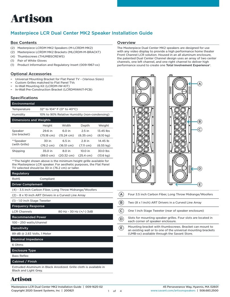
INSTALLATION OPTIONS
The Artison LCR
OM
Speakers were designed
to
have multiple installation options using
the included hardware and brackets.
•Attachment
to
any Flat Panel TV (FPTV)
in
aTablestand
or
Wall Mounted installation.
•On-Wall/Surface Mounting.
Please read the instructions below before attempting your installation.
INSTALLATION PROCEDURES
The Thin UMB was designed
in
compliance with the VESA Mounting Standards. When
using athird party FPTV wall-mount, the Thin UMB's are placed between the FPTV
chassis
and
the FPTV wall-mount.
In
cases where the display utilizes atable top stand,
the Thin UMBs can
be
attached directly
to
the FPTV's chassis.
1.
Components
Needed
for
Installation:
1.1. Wall
Mounted
FPTV and LCR OM: Thin UMBs, Mounting Screws with Collar
Washers and Third Party Wall-Mount Bracket.
1.2. Tabletop FPTV and LCR
OM:
Thin UMBs, and Mounting Screws with Collar
Washers.
REMOVAL OF FPTV CURRENTLY INSTALLED
2.
Ifyour FPTV
is
currently wall mounted, disconnect any wiring connections
and
remove
the FPTV from the wall mount. NOTE:
This
step
may
require
two
or
three people.
3.
Place FPTV
in
safe location, display side down
on
asoft non-abrasive surface.
4.
Remove any existing mounting brackets and screws from the VESA mounting points
on
the rear
of
the FPTV.
THIN UMB PLACEMENT
5.
Locate the Thin UMBs, loosen the 8mm (5/16") Clamp Bolts
on
each end.
6.
Extend the Slider Arms
so
that they are approximately the FPTV width.
Do
not tighten
the clamp bolts yet.
7.
Position one Thin UMB across the top mounting points, one Thin UMB across the
bottom set ofmounting points. Center the Thin UMBs horizontally
on
the display. This
will ensure equal extension ofthe Slider Arms
in
both directions. NOTE:
If
the
Slider
Arms
do
not
extend
far
enough
to
reach
both
sides
of
the FPTV
or
if
the
FPTV's
mounting
points
do
not
fit
within
Aluminum
Main
Bar's
slot
width,
then
your
installation
will
require aThin
Long
Main
Bar
(Thin LONG-MB).
4

SLIDER ARM POSITION BASED ON FPTV THICKNESS
8.
Depending
on
the FPTV depth the Slider Arm Position and use of LCR Extension
Plates will vary. Refer to the following;
TABLE
1and FIGURES 1-6, to see how best
to setup your Thin UMB.
9.
If
TABLE
1calls for the 'Backward' position. Remove the Slider Arm from the
Aluminum Main Bar, rotate 180 degrees, and reinsert into the Aluminum Main Bar.
FPTV
Thin
UMB
Screw
Extension
Minimum
Figure
Thickness
Slider
Arm
Position
Plate TV Wall
Mount
Position
Bracket
Depth
10.28"
-1.0"
Backward Back No 1.54"
21.0" -1.75" Backward Front No 0.82"
31.5" -2.25" Forward Back No 0.32"
42.0" -2.75" Forward Front No 0
52.9" -3.75" Forward Back Yes 0
63.4" -4.4" Forward Front Yes 0
TABLE
1
ALIGNMENT OF THE SLIDER ARMS
10. Align the outer edge ofeach Slider Arm should be flush with the outside edge of the
display's bezel. If you are using the Extension Plate align this surface with the
display bezel. Refer to FIGURES 1-6.
11. Tighten the clamp nuts
on
the UMB using the 8mm (5/16") wrench. This will align
the LCR correctly
so
the Grille will be flush to the side of the FPTV.
5

39.3mm
[1.54"]
20.9mm
[0.82"]
8.2mm
[0.32"]
7mm
[0.28"]
FIGURE 1
25.4mm
[1.00"]
FIGURE 2
38.1mm
[1
.50"]
FIGURE 3
6

50.8mm
~
[2.00"]
FIGURE 4
73.7mm
[2.90"]
~--------------~-------~~~~===~=====~~~~
_
~U
~-------------~-----~~~==-=-==~=~~7
v
~
=_=__
~:,V'
-~--c.r--
FIGURE 5
86.4mm
[3.40"]
FIGURE 6
7

FOAM DAMPENERS
12. The foam provides both damping for the mounting system and stabilizes the speaker.
The pads should
be
attached to the television surface behind the Slider Arm. The
foam
is
intended to
be
highly compressed to fit under the Slider Arm.
13. Expose the adhesive backing by folding asmall corner of the protective paper back
on
itself. Then unfold the paper and remove.
14. Place the
2"
x
2"
x
1"
Foam Dampeners to the TV chassis directly underneath the
Slider Arms close to the speaker. If there
is
alarge gap between the Slider Arm and
TV chassis two pads may be stacked
on
top
of
each other. Refer
to
FIGURES 7&
8.
~--
FIGURES 7 & 8
8

HARDWARE KIT
15. Mounting Screw Selection
15.1. Thread Pitch: M4, M5, M6, M8, or M10.
15.1.1. Match the threads
in
the FPTV chassis to one from the kit.
15.2. Screw Length: 13,
18
or 25 mm.
15.2.1. First, check the thread depth of the mounting points
on
the FPTV.
15.2.2. Select alength that will accommodate the Thin UMB (Depth =7mm), third
party wall-mount, and washers. Allow for 5 - 8 mm ofscrew threads into the FPTV
chassis.
Be
sure to account for the maximum thread depth into the TV.
NOTE:
For
tablestand
installations
without
additional
mounting
hardware,
select
the
smallest
length,
13
mm.
16. Collar Washers: M4, M5, M6 or M8.
16.1. The collar washer will fit snugly around your selected machine screw and fill
the excess area
in
the slot
of
the Thin UMB. NOTE:
Collar
washers
are NOT
needed
for
M10
screw.
17. Flat Washer: Select awasher that fits around the selected Mounting Screw.
18. Using the selected components from Steps
1.1
&1.2., refer to FIGURES 9&10
to
assemble the components to the FPTV chassis. NOTE:
Tighten
all
hardware
securely.
19. Attach the FPTV to the wall.
9

FIGURE 9
FIGURE 10
10
THIN UMB COLLAR WASHER
FLAT WASHER
MOUNTING SCREW
THIN UMB
COLLAR WASHER
WALL
MOUNT BRACKET
FLAT WASHER
MOUNTING SCREW

MOUNTING THE LCR
OM
BRACKET
TO THE THIN UMB
20. Remove the LCR
OM
Bracket from the speakers by loosening the 2thumbscrews
in
acounter-clockwise direction. Refer
to
FIGURE 11.
21. Carefully slip off the bracket. NOTE:
DO
NOT place
the
LCR
OM
face
down
as
this
may
permanently
damage
the
drivers.
22. Attach the LCR
OM
Brackets to the Slider Arms using the 3mm Allen Head Bracket
to Bracket (B/B) Screws. Refer to
TABLE
1for the correct screw location.
23. Loosely attach using the B/B Screws to hold the LCR
OM
Brackets
in
place. Only 2
screws per slider arm are required.
24. Using atape measure, vertically center the LCR
OM
Brackets by having equal
distances from the ends
of
the bracket to the top and bottom
of
the FPTV edge.
Then tighten the Bracket to Bracket Screws. Refer
to
FIGURE 12.
r
----.r
:
[.~---=---
FIGURE
11
11

FIGURE 12
12
x

MOUNTING THE LCR
OM
SPEAKER INTO LCR
OM
BRACKET
25. Carefully slide the LCR
OMs
into the vertical bracket that
is
now mounted
to
the
display. Place each speaker on their corresponding sides of the television. The
OualMono Center Channels should
be
located
on
the top half
ofthe
display. Refer
to
Figure 13.
26. Using the thumbscrews loosely re-attach the speakers. Adjust the front
to
back
speaker position using the slot until the front edge
is
approximately 1/4" behind the
front surface of the bezel.
27. Tighten the thumbscrews to hold the speaker
in
place. NOTE: It
is
best
to
perform
final
alignment
of
your
speaker
after
wiring
and
grilles
are installed.
DualMono Center Channels
----+~
I+-4
-Left Channel Right Channel
FIGURE 13
13

GRILLE INSTALLATION
28. Grilles are held to the speaker by Hook and Loop fasteners, commonly known as
Velcro®. All LCR
OM
Grilles have 2large hook pads. The woofer motors have the
Loop surface.
29. Align the grille with the top and bottom edges
of
the FPTV, directly over the face
of
the speaker baffle.
30. Press the grille firmly onto the woofer motor surfaces.
31. The grille can
be
removed easily by simply pulling on the grille to separate the Velcro
pads.
32. Perform final adjustment to the speaker's front /back alignment using the
thumbscrews. The grille edge should match the bezel height
of
the FPTV as shown
in
Figures 1-6.
14

ON-WALL INSTALLATION OF THE LCR
OM
1.
Remove the LCR
OM
Bracket from the speakers by loosening the 2thumbscrews
in
a
counter-clockwise direction.
2.
Carefully slip off the bracket. Refer
to
FIGURE 11. NOTE:
DO
NOT place
the
LCR
face
down
as
this
may
permanently
damage
the
drivers.
3.
The LCR
OM
Brackets have two slots cut through the rear of the part which will
function as asurface mount bracket. Refer
to
FIGURE 14.
4.
Make a hole directly behind the terminal posts
in
the center ofthe speaker bracket for
the speaker wire.
5.
Place each LCR
OM
on
their corresponding sides of the television. The OualMono
Center Channels should
be
located
on
the top half of the display. Refer
to
FIGURE
13.
FIGURE 14
15

WIRING THE LCRS
3CHANNEL METHOD (Left, DualMono Center and Right)
1. Operate the terminals by firmly pressing on them. An opening will be exposed in the side of
the terminal. Slip about 9mm (3/8") of bare speaker wire into this opening hole and release
the terminal. The spring loaded terminal will now securely hold the wire
in
place. 16 gauge
is
the minimum requirement. Depending upon total wire length alarger gauge may be used. 12
gauge is the maximum that will fit into the terminals.
2.
Left
and
Right
Channels
2.1. Connecttwo conductor speaker wire between each channel and the receiver or amplifier.
Mind the polarity of the wiring is consistent.
(+
to
+,
-to
-)
3.
DualMono
Center
Channels
3.1. Using the supplied 2meter speaker wire, connect both center channels together
in
parallel. This
is
done by connecting Red to Red and Black to Black, (+ to
+,
-to -).
3.2. Connect two conductor speaker wire between one
of
the DualMono Center Channels
and the receiver or amplifier. The wire from the amplifier and the wire from the opposite
center channel should be twisted together and placed
in
the terminals. Mind the polarity
of
the wiring is consistent.
(+
to
+,
-to
-)
4. Refer to FIGURE 15.
5.
NOTE:
This
can
be
achieved
by
using
2
runs
of
4
conductor
speaker
wire.
One
run
per
side
of
the
FPTV. Separate
the
4
conductors
into
2
pairs.
Connect
one
pair
to
each
channel.
The
parallel
connection
of
the
DualMono
Center
Channels
can
be
made
at
the
amplifier.
2CHANNEL METHOD (Left/Right Stereo)
1. Using asingle conductor of speaker wire, connect the negative terminal ofthe Left Channel to
the positive terminal
of
the DualMono Center Channel
in
the same cabinet. This puts the two
channels in series.
2. Similarly, connect asingle conductor from the negative terminal of the Right Channel to the
positive terminal
of
the DualMono Center Channel
in
the same cabinet.
3. Using two conductor speaker wire, connect the Left and Right channel outputs ofthe receiver
or amplifier to the pair of unused +and -terminals on each corresponding side.
4. Refer to FIGURE 16.
16

Right
Center
Stage
Tweeter
Right
Channel
Right
Center
Stage
Tweeter
Right
Channel
.""
Top
Rear
/
I~~
~~I
r'l
--
3
CHANNEL
METHOD
~
~
~
I~~
!)lII@§) I
/
""
11::
......
-+
"-
Center
Right
.o
()
Amplifier
o
O..e
.:t..
Left
~
~
-
FIGURE 15
""-
Top
Rear
/
I I
I~@~
e=@~
I
y
~
y
~
¥!
2
CHANNEL
METHOD
"
~
::::::.
~
.)1;;; I
I
,-
~l·
••
.2
..1-
-
I
1/
"-
"\,l
\1+
Right
Amplifier
I-0
0.h.
• Q nleft
~
FIGURE 16
17
Left
Center
Stage
Tweeter
Left
Channel
Left
Center
Stage
Tweeter
Left
Channel

FINE TUNING YOUR LCR-DM SPEAKERS
Satellite
/
Subwoofer
Crossover
Frequencies:
P-LCR-DM &S-LCR-DM:
•'SMALL' Speaker
on
AN
Receiver /Processor
•Crossover Frequency: 85 Hz
•Crossover Slope:
12
dB/octave
M-LCR-DM:
•'SMALL' Speaker
on
AN
Receiver /Processor
•Crossover Frequency: 80 Hz
•Crossover Slope:
12
dB/Octave
Stage Tweeter
ON
/OFF Switch:
This located
on
the front baffle of each speaker below the Left/Right Channel Woofer.
•
In
most applications, the Stage Tweeter should be ON. The Stage Tweeter widens the
Left &Right Channel separation
by
directing high frequency, 6kHz and up, against the
adjacent rear wall the flat panel is mounted onto.
•Turn the Stage Tweeter OFF for installations where the speakers and FPTV are flush
mounted into recessed cabinetry.
Adjustable Tweeters:
The P-LCR-DM
is
equipped with adjustable front firing
VifaXT25
Tweeters.
•DualMono Center Channel Tweeters should both be aimed towards the center of your
primary listening area.
•Left and Right Channel Tweeters should
be
aimed
to
the respective Left and Right sides of
your primary listening area.
18

19

SPECIFICATIONS &DIMENSIONS:
Masterpiece LCR DualMono
M-LCR-DM
Dimensions:
Driver Complement:
Cabinet IFinish:
Frequency Response:
Recommended Power:
Nominal Impedance:
Sensitivity:
Enclosure Type:
System Weight:
29.6" x6.3" x2.4", HWD Overall
30.0" x6.5" x2.6", HWD
wI
Minimum Grille
Mounting Depth 2.1"
:5
(TV +Thin UMB +Wall Mount)
For use with FPTV's 55" or larger: H
~
30.0", D0.28" -4.4"
2.
5%" Kevlar, Long Throw, Inverted Magnet, MidrangelWoofer
2.
8 x
1"
ART Drivers
in
Curved Line Array
1.
25mm Stage Tweeter
Extruded Aluminum IBlack Anodized;
Grille Cloth available
in
Black or Light Grey
80 Hz -30 kHz ± 3 dB
125 -250 Watts
60
86 dB @2.83 Volts,. 1Meter
Acoustic Suspension
28 Ibs. (13 kg.) inc!. Speakers, Mounting Hardware &Grilles
20
This manual suits for next models
6
Table of contents
Other Artison Speakers manuals

Artison
Artison LRS-W User manual

Artison
Artison LCR DualMono LCRDM-IW-KIT User manual

Artison
Artison SB-1 User manual

Artison
Artison MEZZ-8-SURR User manual

Artison
Artison 5B-1 User manual

Artison
Artison Sketch LCR DualMono MK 2 User manual

Artison
Artison ARCHT-6 User manual

Artison
Artison M-LCR/UMB User manual

Artison
Artison Sketch LCR DualMono MK 2 User manual

Artison
Artison LRS User manual