Artison M-LCR/UMB User manual

INSTALLATIO
GU
DE
Masterpiece
M-LCRJU
B
Portra-t P-LCRJUMB
Sketch
S-LCRJU
B
®

2

Thank you for choosing the Artison LCRs. We are pleased that you have selected
our high-performance audio products.
INTRODUCTION
The following information will guide you through the installation of your Artison LCRs.
The Artison LCRs are designed to attach directly to any flat panel display, whether placed
on
astand or mounted to the wall. G-LCR Grilles are available to match the height and
complement the color of all plasma or LCD displays 42 inches and above.
Your LCR box should contain the following:
• 1 Pair LCRs
• 1 Pair Universal Mounting Brackets (UMB)
• 1 Hardware Kit
oUMB Mounting Screws and washers (Assorted sizes and lengths)
oUMB Straps
o6mm Allen Wrench
o3mm Allen Wrench
o3mm Bracket to Bracket
(B
to
B)
Screws
If you are missing any of these parts or if you need assistance during the
installation of your Artison LCRs, please contact Artison's Customer Service
Department during normal business hours, Pacific Time at (775) 833-4344.
3

MOUNTING LCRS USING
THE UNIVERSAL MOUNTING BRACKET (UMB)
When the television
is
mounted
to
the wall, the UMB and it's components are designed
to
sandwich between the wall mount bracket and the display. When the television is utilized with a
table top stand, these components can
be
attached directly
to
the back of the plasma using the
wall bracket mounting points.
1. Remove the display from its box or where it
is
mounted and lay it display-side down
on
alarge,
flat, soft surface. NOTE:
This
step
may require TWO PEOPLE.
2. Find the correct size and quantity of screws and washers from the supplied hardware
selection located
in
the LCR Box.
3. Position the both UMBs
on
the rear of the display so that the slots line
up
with the wall-mount
points
on
the television. Center the UMBs horizontally
on
the back of the television, this will
allow for even adjustment of the Slider Arms.
3.1
In
aTable
Top
installation, continue to Step
4.
3.2
In
aWall-Mount installation the Wall-Mounting bracket should
be
placed
positioned at this time, SEE FIGURE 1.
4.
Using the selected screws and washers from Step 2sandwich the UMB the between and Wall
Mount Bracket and the TV by tightening the screws until they are snug.
5.
Loosen the clamps holding the Slider Arms and adjust them as shown
in
FIGURE
2.
When
finished the outer edge of each adjustable bracket should
be
flush with the outside edge ofthe
display. The ribbed portion of abracket can extend beyond the side surface of the display.
6.
You may now hang your Flat Panel Display
on
the wall, or place it
on
it's table stand.
4

FIGURE 1
FIGURE 2
5

SPECIAL MOUNTING INSTRUCTIONS FOR DISPLAYS
WITH UNEVEN OR RAISED AREAS ON THE BACK
Some Flat Panel Displays have an uneven
or
raised section on the back. This uneven area is
sometimes
in
line with the bottom wall mounting points.
Wall Mount
In this case, the lower UMB should be positioned as shown in FIGURE 3. Use the spacers
provided in the Hardware Kit to maintain the properdistance away from the set for the wall mount
brackets.
If the Wall Mount Bracket
in
your application will not work in this manner, use the supplied UMB
Clamp Bars to secure the lower UMB in place.
Table Top Stand
Use the supplied long flat bars (UMB Clamp Bars) to clamp the lower UMB. There is asupplied
washer that fits between the UMB Clamp Bars and the Table Top Stand Vertical Posts. SEE
FIGURE 4.
6

FIGURE 3
FIGURE 4
7

MOUNTING
THE
LCR
TO
THE
UMB
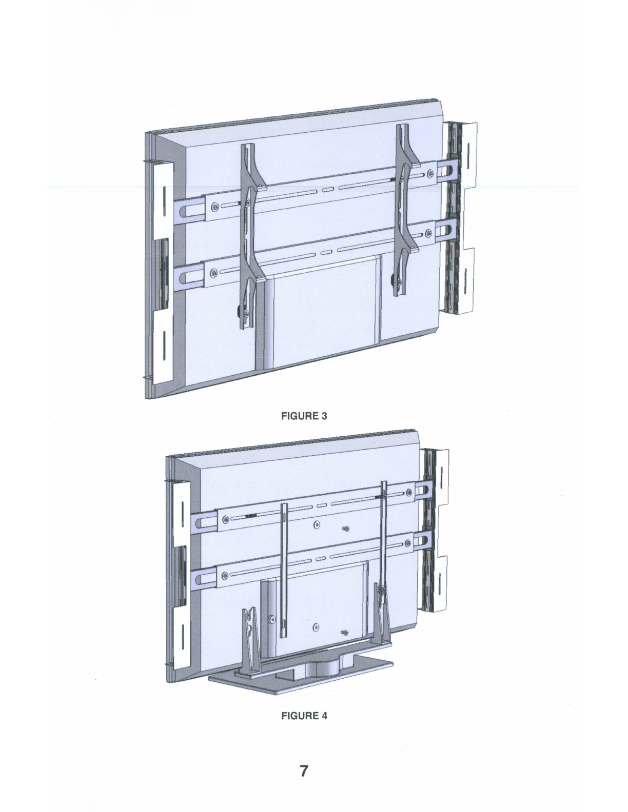
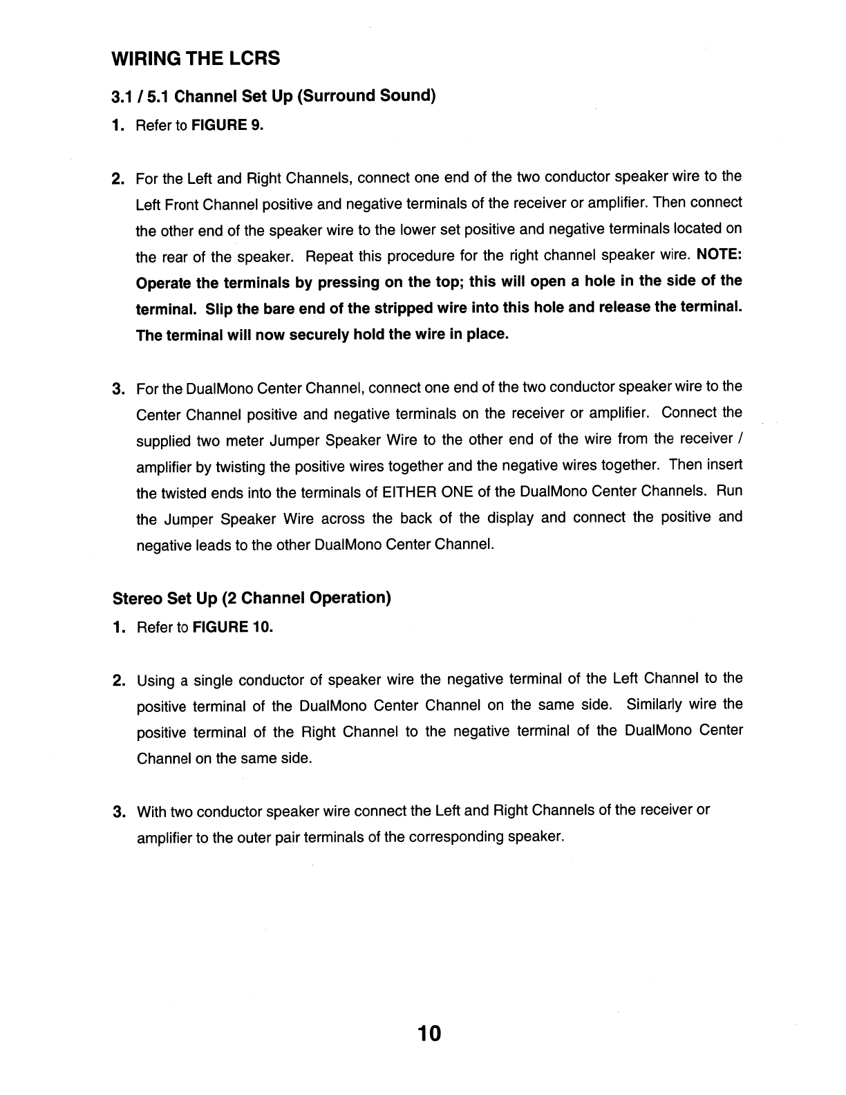
Every LCR comes with an attached Main Bracket, which is used to fasten the speakers to the
UMB. The Main Bracket may also used to mount the LCR speakers to the wall.
1.
Remove the Main Bracket by loosening the LCR Knobs
in
acounter-clockwise direction.
2.
Carefully slip the Main Bracket off of the LCA.
SEE
FIGURE
5.
WARNING:
DO
NOT place
the LCR on
it's
face as
this
may permanently damage the drivers.
3.
Locate the center of each side of the display and place ashort piece of masking tape there.
Using atape measure, determine the exact vertical center of the display and make amark on
the tape with apen or pencil. Double-check your measurements.
SEE
FIGURE 6.
4.
Place the LCR's Main Bracket against the UMB that is now attached to the display. Insertthe
Bracket to Bracket Screws (supplied in your Hardware Kit) to loosely hold the Main Bracket in
place, do not tighten them yet. Align the center mark on the Main Bracket with the center mark
on your display. Then tighten the Bracket to Bracket Screws. NOTE: Only 2screws per
side are needed
to
secure the Main Brackets (one at the
top
and one at the bottom).
The spare holes in the UMB are to accommodate different
flat
panel displays.
5. Carefully slide the LCR onto the Main Bracket that is now mounted to the display. NOTE:
Place each LCR on their corresponding sides
of
the
television. The
DualMono™
Center Channel should be located toward the
top
of
the display, with the drivers
pointing inward.
SEE
FIGURE
7.
6.
Use the knobs that you removed earlier to loosely re-attach the speakers. Slide the LCRs
back and forth until the front edge is approximately 1/8" behind the front surface
of
the display.
Tighten the knobs to hold the speaker
in
place.
SEE
FIGURE 8. NOTE: It may be easier
to
perform final alignment after
your
LCRs have been wired as described in the next
section
of
this
Guide.
8

FIGURE 5FIGURE 6
FGURE 7
FIGURE 8
9

WIRING THE LCRS
3.1
I
5.1
Channel
Set
Up
(Surround
Sound)
1. Refer to FIGURE
9.
2. For the Left and Right Channels, connect one end of the two conductor speaker wire to the
Left Front Channel positive and negative terminals of the receiver or amplifier. Then connect
the other end of the speaker wire to the lower set positive and negative terminals located
on
the rear of the speaker. Repeat this procedure for the right channel speaker wire. NOTE:
Operate the terminals by pressing on the top; this will open ahole in the side
of
the
terminal. Slip the bare end of the stripped wire into this hole and release the terminal.
The terminal will now securely hold the wire in place.
3. For the DualMono Center Channel, connect one end of the two conductor speaker wire to the
Center Channel positive and negative terminals
on
the receiver or amplifier. Connect the
supplied two meter Jumper Speaker Wire to the other end of the wire from the receiver /
amplifier by twisting the positive wires together and the negative wires together. Then insert
the twisted ends into the terminals of EITHER ONE of the DualMono Center Channels.
Run
the Jumper Speaker Wire across the back of the display and connect the positive
and
negative leads to the other DualMono Center Channel.
Stereo
Set
Up
(2
Channel
Operation)
1. Refer to FIGURE 10.
2. Using asingle conductor of speaker wire the negative terminal of the Left Channel to the
positive terminal of the DualMono Center Channel
on
the same side. Similarly wire the
positive terminal of the Right Channel to the negative terminal of the DualMono Center
Channel
on
the same side.
3. With two conductor speaker wire connect the Left and Right Channels of the receiver or
amplifier to the outer pair terminals of the corresponding speaker.
10

Right
Cente
Stage
Tweeter
Right
Channel
.~
/
-
Top
---.
I
Re
r
~@
~
c==:>
.,......
@~
'¥o'
"I
~
I::
~
3. /5. anne e
~
~
~
I
9d~
.-
c:::::::>
~
@
f:=D
~
......
(-)
(+)
(+)
(-)
(-)
(+
.........
--
~
/"
............
Right -•
Center
-e t
-•
-
Amplifier
•-
-
age
ee
er
ef
Cae
FIGURE 9
Right
Center
Top
Le
Ce
ear
er
@)
c:=::::>
Seeo e - p
Stage
Tweeter
Sagel
ee
e
~i
»c::=:>
Right
Channel
(+)
(-)
Le
Channe
mp
ifier
FIGURE 10
11

FINE TUNING YOUR LCRS
Crossover Setting:
The DOLBY HIGH PASS SETTING
in
most receivers
is
80Hz when set
in
the SMALL SPEAKER
position. We have optimized the S-LCR, P-LCR, and M-LCR speakers for this setting.
Adjusting the Settings on the
LCR
Speakers
Stage Tweeter
Settings:
The switch turns the tweeter on and off.
In
most installations, the Stage Tweeter should be left
on.
Turning on the Stage Tweeter widens the Left/Right Channels sound stage. Since it
is
difficult
to
see the markings when the system
is
installed, you can tell that the switch
is
in
the
ON
position by
feel. When the switch
is
set towards the outside of the system (away from the display) it is
in
the
ON
position.
Presence
Control
Settings:
The Presence Control changes the DualMono Center Channel tweeter level to compensate for
differing room acoustics. This can be adjusted with the three-position switch located
in
the Center
Channel terminal cups. NOTE: Presence
Control
switches
on
both
speakers
should
be
set
to
the
same
positions
for
proper
balance
of
the
center
image.
-
Normal
-The toggle
is
set towards the outside of the system, away from the display. Start with
the switches
in
this position first.
-Decreased -The toggle
is
in
the center position. This setting
is
for acoustically "hard", highly
reflective rooms.
-Increased
-The toggle is set towards the display. This setting
is
for acoustically "soft", highly
absorbent rooms.
Adjustable
Tweeters:
The M-LCR
is
equipped with adjustable front firing tweeters. Using the angle built into the woofers
as areference, fine tune your LCRs to fit your application. The DualMono Center Channels
should be focused to the center of your listening area. Conversely the Left and Right Channel
Tweeters should be aimed to the Left and Right sides of your listening area.
12

LIMITED WARRANTY
ALL
INTERNET SALES ARE STRICTLY PROHIBITED
This warranty remains
in
effect for five years from the date of purchase for speaker
products and one year for electronic products.
THIS WARRANTY PROTECTS THE ORIGINAL OWNER PROVIDING THAT THE
PRODUCT HAS BEEN PURCHASED FROM
AN
AUTHORIZED ARTISON DEALER
IN
THE UNITED STATES. THE ORIGINAL BILL OF SALE MUST
BE
PRESENTED
WHENEVER WARRANTY SERVICE
IS
REQUIRED. FOR WARRANTY SERVICE
OUTSIDE THE UNITED STATES, CONTACT THE AUTHORIZED ARTISON
DISTRIBUTOR
IN
THE COUNTRY WHERE THE PRODUCT WAS PURCHASED.
Except as specified below, this warranty covers all defects
in
material and workmanship.
The following are not covered: Damage caused by accident, misuse, abuse, product
modification or neglect, damage occurring during shipment, damage from failure to follow
instructions contained
in
the Owners Manual, damage resulting from the performance of
repairs by someone not authorized by Artison, or any claims based
on
misrepresentations by the seller. This warranty does not cover incidental or
consequential damages. It does not cover the cost of removing or reinstalling the unit.
THIS WARRANTY IS VOID IF THE SERIAL NUMBER HAS BEEN REMOVED
OR
DEFACED, OR IS PURCHASED
ON
THE INTERNET, WORLD WIDE WEB, MAIL
ORDER, 800, 888, 877 TELEPHONE NUMBERS
OR
THROUGH ACATALOG.
This warranty gives you specific legal rights. You may also have other rights, which vary
from state to state. Some states do not allow the exclusion or limitation of incidental or
consequential damages or limitations
on
how long
an
implied warranty lasts, so the above
may not apply to you.
Please make note of the following information and retain for your record.
Product Name Model Number _
Store Name Purchase Price _
HOW TO OBTAIN SERVICE
Please call us at (775) 833-4344, or write to: ARTISON (Attention: Customer Service
Department), 774 Mays Blvd., Suite 10-183, Incline Village, NV 89451.
We
will promptly advise you of what action
to
take.
We
may direct you to
an
authorized Artison
Service Center or ask you to sena your speaker to the factory for repair.
You
will need to present
the original bill of sale to establish the date of purchase. PLEASE
DO
NOT SHIP YOUR
ARTISON PRODUCT
TO
THE FACTORY
FOR
REPAIR WITHOUT PRIOR AUTHORIZATION.
PLEASE
DO
NOT RETURN PRODUCT TO THE ABOVE ADDRESS, IT IS NOT ASERVICE
LOCATION. You are responsible for transporting your product for repair and for payment of any
initial shipping charges. However, we will pay the return shipping charges if the repairs are
covered under warranty.
13


ARTISON®
Information
for
Fujitsu
Plasma Owners
Some Fujitsu plasma models have araised section on the rear of the sets that
house the input /output terminals. This area
is
in
line with the lower main
bracket of the UMB (Universal Mounting Bracket).
In
this case, the lower UMB
should
be
set
on
top of the raised area using the wall mount to clamp the main
bar against the television as shown below. Use the spacers provided
in
the UMB
Kit to maintain the proper distance away from the set for the wall mount brackets.
Wall Mount Installation

When attaching the UMB
in
astand mount installation, use the bars provided
with the Grille Kit
in
place of the wall mounts to clamp the lower UMB. Note that
there is asupplied washer that fits between the UMB Clamp Bars and the Fujitsu
Stand Vertical Posts.
Stand Mount Installation

Name
Company
Name
of
Dealer
Productlsl
Telephone
Number
Address
Email
Address
of
Dealer
Model
Numbers
Date/Price
Serial
Numbers
Please
rate
your
overall
experience
with
the
dealer.
0
Excellent
0
Good
0
Average
0
Poor
2
Where
did
you
first
learn
about
ARTISaN?
0
Magazine
0
Newspaper
0
Friend
0
Salesperson
0
Brochure
0
Other
_
3
What
other
brand
of
speakers/subwoofers
did
you
consider?
0
Polk
0
Bose
0
Sonance
0
Infinity
0
JBL
0
Boston
Acoustics
0
Mirage
o
Paradigm
0
Niles
0
KEF
0
Definitive
Technologies
0
Other
_
4
Please
check
the
most
important
factors
influencing
this
purchase?
o
Quality
of
sound
0
MagaZine
Review
0
Recommendation
of
salesperson
0
Appearance
0
Technical
Specifications
0
Ease
of
operation
o
Recommendation
of
friend/family
0
Value
for
price
0
ARTISON's
reputation
0
Previous
owner
of
ARTISaN's
products
o
Other
_
5
What
is
the
primary
use
for
this
purchase?
0
Music
playback
0
Front
main
speakers
0
First
speaker
purchase
0
Movie/Home
Theater
o
Rear
(surround
sounorspeakers
0
Replacing
speakers
0
Add
to
existing
system
0
Other
_
6.
Which
of
these
specialty
magazll1es
do
you
read?
0
Sound
&
Vision
0
Audio
Video
Interiors
0
Stereophile
0
Stereophile
Guide
to
Home
Theater
o
Absolute
Sound
0
Architectual
Digest
0
Consumer
Reports
0
Home
Theater
0
Other
_
70
Male
0
Female
8
Age
Group?
0
Under
18
0
18-24
025-34 035-44 045-54 055-64 0
Over
64
9
Family
income?
0
Under
$15.000
0
$15.000
-
24,999
0
$25.000
-
$49.000
0
$50.000
-
$74.999
0
$75,000
-
$100.000
0
Over
$100.000
10
Education
(Please
Check
which
category
applies)
0
High
School
0
Some
College
0
Completed
College
0
Graduate
School
11.
What
is
your
occupation?
0
Self
employed/Owner
0
Student
0
Professional
Technical
0
Homemaker
0
Upper
Management
o
Retired
0
Middle
Management
0
Sales/Marketing
0
Clerical/Service
Worker
0
Laborer/Tradesman
12
00
you
have
any
comments
about
your
new
ARTISaN
products?
_
o
Yes.
I
would
like
to
receive
ARTISaN
mailings
when
they
become
available.
0
No.
Please
do
not
send
me
ARTISaN
mailings
WE
WOULD
LIKE
TO
THANK
YOU
FOR
CHOOSING
ARTISON
At
Artison,
we
are
dedicated
to
the
art
and
technology
of
sound,
providing
you
with
high
quality
products
that
bring
you
closer
than
ever
to
the
live
performance
In
order
to
maintain
our
high
standards,
we
would
like
to
better
understand
your
needs.
please
fill
out
this
questionnaire
card
and
return
it
to
us
within
TEN
days
LIMITED
WARRANTY
This
warranty
remains
in
effect
for
five
years
from
the
date
of
purchase
for
speaker
products
and
one
year
for
electronic
products
THIS
WARRANTY
PROTECTS
THE
ORIGINAL
OWNER
PROVIDING
THAT
THE
PRODUCT
HAS
BEEN
PURCHASED
FROM
AN
AUTHORIZED
ARTISON
DEALER
IN
THE
UNITED
STATES
THE
ORIGINAL
BILL
OF
SALE
MUST
BE
PRESENTED
WHENEVER
WARRANTY
SERVICE
IS
REQUIRED
FOR
WARRANTY
SERVICE
OUTSIDE
THE
UNITED
STATES.
CONTACT
THE
AUTHORIZED
ARTISON
DISTRIBUTOR
IN
THE
COUNTRY
WHERE
THE
PRODUCT
WAS
PURCHASED
Except
as
specified
below,
this
warranty
covers
all
defects
in
material
and
workmanship
The
following
are
not
covered
Damage
caused
by
accident.
misuse,
abuse,
product
modification
or
neglect.
damage
occurring
during
shipment,
damage
from
failure
to
follow
instructions
contained
in
the
owners
manual,
damage
resulting
from
the
performance
of
repairs
by
someone
not
authorized
by
Artison,
or
any
claims
based
on
misrepresentations
by
the
seller.
This
warranty
does
not
cover
incidental
or
consequential
damages
It
does
not
cover
the
cost
of
removing
or
reinstalling
the
unit
This
warranty
is
void
if
the
serial
number
has
been
removed
or
defaced
You
are
responsible
for
transporting
your
product
for
repair.
However,
Artison
will
pay
return
freight
charges
if
the
repair
is
covered
under
warranty
This
warranty
gives
you
specific
legal
rights.
You
may
also
have
other
rights
which
vary
from
state
to
state
Some
states
do
not
allow
the
exclusion
or
limitation
of
incidental
or
consequential
damages
or
limitations
on
how
long
an
implied
warranty
lasts,
so
the
above
may
not
apply
to
you
Please
make
note
of
the
following
information
and
retain
for
your
record
Product
Name
Model/Serial
Number
_
Store
Name
_
Purchase
Price
_
HOW
TO
OBTAIN
SERVICE
Please
call
us
at
(7751
586-9574,
or
write
to
ARTISON
(Attention
Customer
Service
Department).
774
Mays
Blvd,
Suite
10-183.
Incline
Village,
NV
89451.
We
will
promptly
advise
you
of
what
action
to
take.
We
may
direct
you
to
an
authorized
Artison
Service
Center
or
ask
you
to
send
your
speaker
to
the
factory
for
repair.
You
will
need
to
present
the
original
bill
of
sale
to
establish
the
date
of
purchase
PLEASE
DO
NOT
SHIP
YOUR
ARTISaN
PRODUCT
FOR
REPAIR
WITHOUT
PRIOR
AUTHORIZATION.
PLEASE
DO
NOT
RETURN
PRODUCT
TO
THE
ABOVE
ADDRESS.
IT
IS
NOT
A
SERVICE
LOCATION
You
are
responsible
for
transporting
your
product
for
repair
and
for
payment
of
any
initial
shipping
charges.
However,
we
will
pay
the
return
shipping
charges
if
the
repairs
are
covered
under
warranty

ARTISON
Attention:
Customer
Service
Department
774
Mays
Blvd.,
Suite
10-183
Incline
Village,
NV
89451
Place
Stamp
Here
This manual suits for next models
2
Table of contents
Other Artison Speakers manuals

Artison
Artison Sound Surface 40 User manual

Artison
Artison SB-1 User manual

Artison
Artison LCR DualMono LCRDM-IW-KIT User manual

Artison
Artison LRS-W User manual

Artison
Artison STUDIO 55 SoundBar User manual

Artison
Artison 5B-1 User manual

Artison
Artison Sketch LCR DualMono MK 2 User manual

Artison
Artison Sketch LCR DualMono MK 2 User manual

Artison
Artison MEZZ-8-SURR User manual

Artison
Artison M-LCR-DM User manual