Artistic Licence Rail-Demux User manual

Artistic Licence
Rail-Demux User Guide
Rail-Demux
Version 3-0
User Guide

Page 2
Rail-Demux User Guide
Please read these instructions before using the product.
This product has been designed & manufactured for professional use only.
It should only be installed by a suitably qualied technician and in accordance with
electrical regulations in the country of use.
Unless directed in the instructions there are no user serviceable parts inside the
outer case of this product.
Always disconnect from the power supply when not in use.
Any specic IP rating, where appropriate, is given in the instructions. Unless
otherwise stated this product is designed for indoor use only. If used outdoors it
MUST be installed in an appropriate IP rated cabinet. Do not allow this product to be
exposed to rain or moisture. Do not allow liquid to penetrate the product.
Please recycle all packaging.
Copyright © Artistic Licence Engineering Ltd. All rights reserved.
Download the user guide by scanning the following QR code:

Page 3
Rail-Demux User Guide
Reference Type Description
1LED Data indicator
2LED Power indicator
3Connection DMX512 Input
4Connection DMX512 Loop &
Term**
5Power input Ground
6 Power input 24 VDC
7 - 8 Connection Analogue outputs
9Connection Ground (outputs)
Connections
Mounting Diagram
To use the surface mount option push the three bottom tabs out until they click into place. We
recommend using an M4 Pan head screw.
** A passive loop-through connection allows
onward connection to other DMX512 devices. If
this feature is not required then the signal must
be terminated. The product contains an internal
termination resistor. This is enabled by tting a
wire link between Ter m and DAT+.

Rail-Demux User Guide Page 4
DMX512 Wiring
XLR Pin
(Convention)
Function Colour
1Ground Black
2Data - Blue
3Data + Red
Internal Earth and Isolation
Circuit Description
DMX512 Input
(including Loop through)
Type: Non-isolated
Pin 1: Connects to Internal Logic
Ground
Analogue Output Ground referenced
Internal Logic Ground Connects to Ground Power Input
Overview
Rail-Demux is a DIN-rail or surace mounted device that converts DMX512 into 16 analogue
outputs. The standard that denes the output is ANSI E1.3 - 2001 (R2016).
DMX512 to analogue conversion has two key applications: upgrading older analogue dimmers
and driving uorescent ballasts tted with a 0-10V control facility.
The control interface uses DMX512 (all standards) and RDM or Remote Device Management.
The RDM interface allows the start address to be set by the controller over the DMX512 cable.
RDM also allows the product to receive rmware upgrades and run diagnostics tests.
DMX512 loop-through and termination options are provided. The product is powered via an
external DC power supply unit.

Rail-Demux User Guide Page 5
Connections
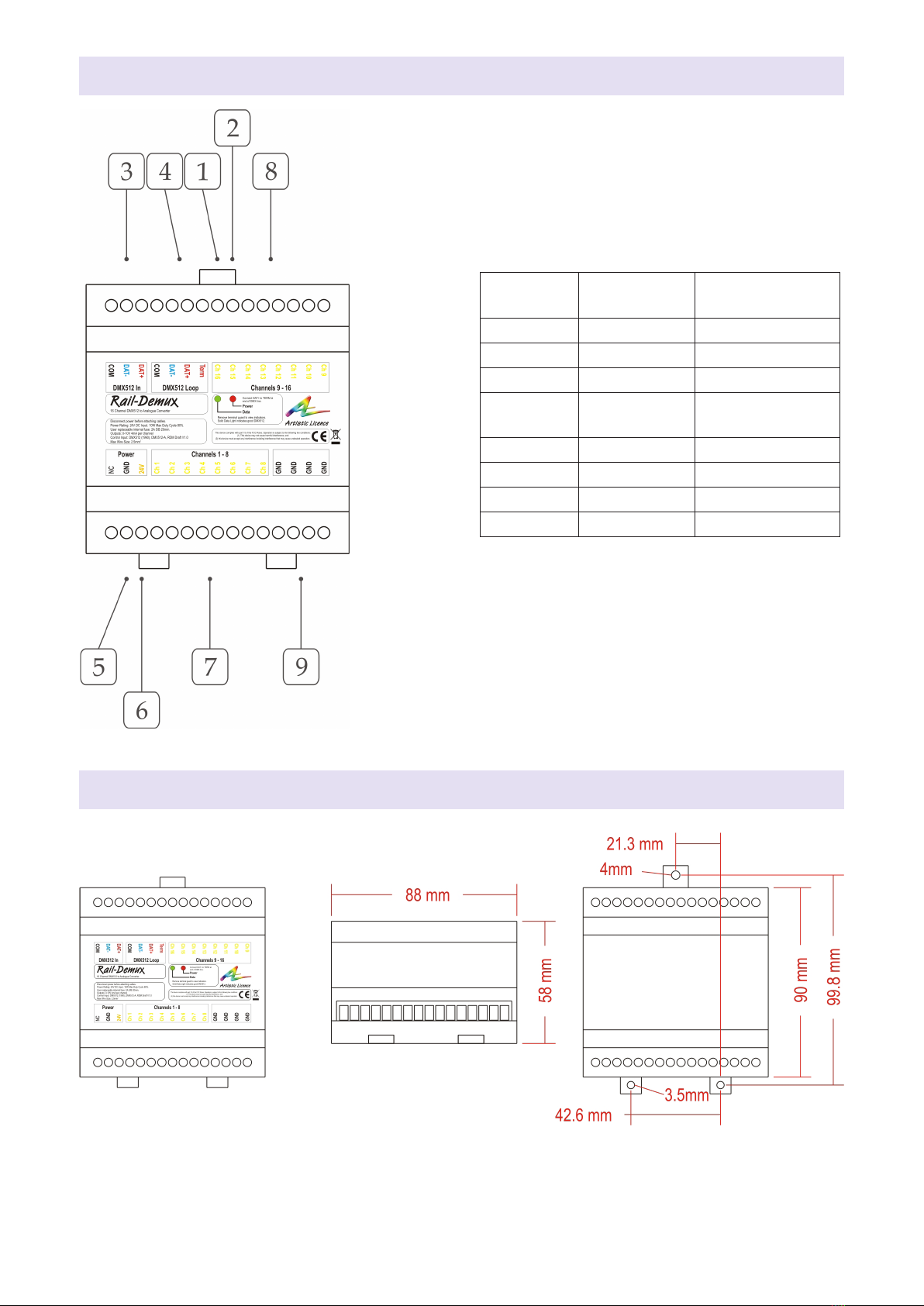
Please refer to the connections diagram.
DMX512 Input & Loop-Through
The DMX512 input is via a 3-pin screw
terminal.
A 4-pin screw terminal passive loop-through
connection allows onward connection to other
DMX512 devices. This enables two or more
Rail-Demux units to be connected in parallel
to increase the number of outputs.
If this feature is not required then the signal
must be terminated. The product contains an
internal termination resistor. This is enabled by
tting a wire link between the screw terminals
that will terminate the DMX line (Term and
DAT+).
Analogue Outputs
Two 8-pin screw terminals are used for the 16
analogue outputs. The standard that denes
the output is ANSI E1.3 - 2001 (R2016).
Output Ground
One 4- pin screw terminal is used for the ground
connection. Multiple control ground wires can
be connected to each of the terminals.
Summary of Key Features
y16 Analogue outputs ANSI E1.3 - 2001
(R2016)
y0 - 10 VDC output
yDMX512 Interface
yRDM V1.0 (E1.20 - 2010)
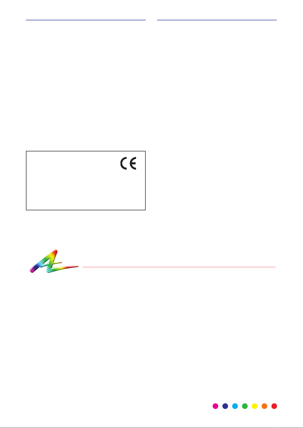
yDIN rail mount
ySurface mount
To adjust or calibrate the output of the Rail-
Demux, use the following procedure:
1. Disconnect the power supply.
2. Gently remove the lid of the DIN rail unit.
3. Locate the calibration resistor (RV1).
This will allow you to decrease or
increase the output voltage range.
4. Replace lid and reconnect to the power
supply.
Ensure that you are grounded before touching
any internal components. You can achieve
this by either wearing an anti-static wristband
or by touching an earthed metal surface at
regular intervals.
Operation
Power
Rail-Demux is be powered from an external
DC power supply (24 VDC). It is recommended
that a ferrite core be tted onto the DC power
lines as close as possible to the Rail-Demux.
This protects the unit from any electrical spikes
that appear on the DC line.
LED Indication
Rail-Demux has green and red LED indicators
under the terminal guard. The display is as
follows:
Data (left):
OFF = No data received
Solid green = Data received
Fla shing gr een = Te st m od e (se e ‘Con guration’
section)
Power (right):
Solid red = Power
Flashing red = Identify

Page 6
Rail-Demux User Guide
The diagram below shows how Rail-Demux could be utilised in a typical application. In this
example, it enables dimming of 16 uorescent ballasts by a DMX controller.
Application Diagram
Wiring Diagram
0 to 10V
Control Lines
0 to 10V
Fixtures
DMX Controller
Rail-Demux
DMX
PSU
... up to 16 outputs
DMX I/P
DMX Loop
Output
Output
Male XLR5 Link for
termination
if loop not in
use
Female XLR5
PSU-24-2-FER
x2

Rail-Demux User Guide Page 7Page 7
Rail-Demux User Guide
Conguration
Rail-Demux uses one channel to control each output, requiring 16 channels in total.
There are various conguration options (including start address programming). These are
accessed using RDM, which requires a suitable programming interface.
One option is Commissioner rdmx, a handheld RDM programming tool available from Artistic
Licence.
Alternatively, Rail-Demux can be connected to an Art-Net network using an interface product
such as artLynx or netLynx. Conguration is then achieved using DMX-Workshop, a PC software
application for managing Art-Net networks (available as a free-of-charge download from the
Artistic Licence website, www.artisticlicence.com).
DMX-Workshop
This windows-based application provides
a convenient means of accessing the Rail-
Demux conguration menus. DMX-Workshop
can also be used for product rmware uploads.
Start address programming
In the DMX-Workshop ‘Node List’ screen,
Rail-Demux appears as an RDM device,
with each output listed as a sub-device (see
screenshot opposite).
If the user wishes all 16 output channels to be
consecutively addressed, this is achieved by
setting the RDM device start address (right-
click on the RDM device entry). Alternatively, if
the user wishes to individually set the address
of each channel, this is achieved by setting
the start address of each sub-device (right-
click on the desired RDM sub-device).
Generally, right-clicking on any entry brings
up a menu of the available options.
RDM device
RDM
sub-devices
The priority of output is as follows (highest at
the top):
1. Test pattern
2. DMX512
Test mode Output priority
Rail-Demux oers two test patterns:
Test 1 = all outputs on
Test 2 = all outputs o
DMX-Workshop (or suitable RDM tool) can be
used to put the product in test mode, which
can be useful during show commissioning or
rehearsals.
To access the data test mode selections,
right-click the Rail-Demux RDM device, then
go to ‘Self test’.

Page 8
Rail-Demux User Guide
Rail-Demux Specication
Mechanical
yHousing: DIN Rail Case
yMaterial: Lexan plastic, UL94-V0 rated
yOverall dimensions: 90 mm (H) x 88 mm
(W) x 58 mm (D)
yWeight: 0.2 kg
yMounting: 35 mm DIN Rail or Surface
Mount
yCountry of manufacture: UK
Environmental
yOperating temperature: 0°C to 40°C
yStorage temperature: -10°C to +50°C
yOperating relative humidity (max): 80%
non-condensing
yIP rating: IP20 indoor use only
yCertication: CE, WEEE, RoHS
yWarranty: 2-year (return to base)
Power & Electrical
yInput voltage: 24 VDC
yInput power (max): 15 W
yInput connector: 2-pin screw terminal (1 no.)
yDuty cycle: 100% @ 25°C
yDC fuse: internal resettable fuse for
control electronics
DMX512 input
yProtocols: DMX512, DMX512(1990),
DMX512-A, RDM V1.0 (E1.20 - 2010)
yInput mode: non-isolated
yInput ESD protection: 12 kV
y3-pin Screw Terminal DMX Input (1 no.)
y4-pin Screw Terminal DMX Loop / Term
(1 no.)
Analogue Outputs
yVoltage: Adjustable 0 - 11 VDC
yCurrent (max): 4 mA
yANSI E1.3 - 2001 (R2016)
ySignal connector: 8-pin screw terminal (2
no.)
yGround connector: 4-pin screw terminal
(1 no.)
Conguration
yStart address (via RDM)
LED Indication
yPower / DMX input
Package Contents
yRail-Demux
Ordering Info
yProduct code: Rail-Demux
Accessories (not included)
yPSU-24-2-FER

Warranty
All products are covered from date of purchase
by a two-year return to base warranty.
By return to base, we mean that the customer
is responsible for all costs of transport to and
from Artistic Licence.
Returns will not be accepted without prior
authorisation. In order to discuss a request to
return goods, please email:
Sales@ArtisticLicence.com
CE Compliance
Rail-Demux is CE compliant when installed
in a shielded and earthed metal case
Compliance
All Products manufactured or sold by
Artistic Licence Engineering Ltd are fully
compliant with the appropriate CE and RoHS
regulations. Product specic information is
available on request.
Waste Electrical & Electronic Equipment
(WEEE)
Artistic Licence is a member of a WEEE
compliance scheme and will happily recycle
any of our products that you, at your expense,
return to us.
Due to our policy of continuing product improvement
specications are subject to change without notice
Artistic Licence
The Mould Making Workshop
Soby Mews
Bovey Tracey
TQ13 9JG
United Kingdom
Telephone +44 (0) 20 8863 4515
Email: Sales@ArtisticLicence.com
Web: www.ArtisticLicence.com
Support@ArtisticLicence.com
Table of contents
Other Artistic Licence Media Converter manuals