Artistic Licence DALItoDMX User manual

Artistic Licence
DALItoDMX User Guide
DALItoDMX
User Guide
Version 1-1

Page 2
DALItoDMX User Guide
Please read these instructions before using the product.
This product has been designed & manufactured for professional use only.
It should only be installed by a suitably qualied technician and in accordance with
electrical regulations in the country of use.
Unless directed in the instructions there are no user serviceable parts inside the
outer case of this product.
Always disconnect from the power supply when not in use.
Any specic IP rating, where appropriate, is given in the instructions. Unless other-
wise stated this product is designed for indoor use only. If used outdoors it MUST be
installed in an appropriate IP rated cabinet. Do not allow this product to be exposed
to rain or moisture. Do not allow liquid to penetrate the product.
Please recycle all packaging.
Copyright © Artistic Licence Engineering Ltd. All rights reserved.
Download the user guide by scanning the following QR code:

Page 3
DALItoDMX User Guide
Ref. Type Description
1LED
Solid: Receiving DALI
commands for active short
addresses
2LED
Solid: Product power &
DALI BUS power present
Flashing: Virtual DALI
devices not commissioned
O: Product power or bus
power or both not connected
3Connection Power input 9-24 VDC
4Connection DALI Input
5LED
Solid: DALI bus power pre-
sent
Flashing: DALI data
present
6DIP Switch See table below
Connections
Dip
Switch
Function
1Not Used
2Not Used
3 & 4 Sets number of virtual DALI devices
(see Table 1 on page 4)
5OFF (default): No dimming curve correction
ON: Exponential curve correction
6OFF (default): Device Mode
ON: Trigger Mode
Mounting Diagram

Page 4
DALItoDMX User Guide
Overview
DALItoDMX converts DALI (DT0 - intensity)into DMX512. It is designed for environments that
require integration between the two protocols. DT8 (colour) is not supported.
Device Mode (normal operation)
In Device Mode (ensure DIP switch 6 is set to OFF), DALItoDMX simulates virtual DALI devices,
each of which controls a single DMX channel. This is shown conceptually in Figure 1 below.
A virtual DALI device acts in the same manner as a normal DALI device and responds to DALI
commands (see Appendix 2 for detail).
All the standard DALI addressing modes (Broadcast, Group, Device and Scene) are supported.
In its normal mode of operation (Device Mode),
the product enables an existing DALI controller
to control DMX xtures.
DALItoDMX features a second mode of
operation (Trigger Mode), which can be useful
in some scenarios (see page 6).
DALItoDMX oers the user the option to
simulate 1, 4, 16 or 64 DALI devices. The
choice is made via setting DIP switches 3 and
4 as shown in Table 1. The DMX channels
that are not being used are set to zero.
We recommend that DALItoDMX is installed
on its own DALI circuit. However, if the
Selecting the number of devices DIP Switch
3
DIP Switch
4
Total no. of
Virtual Devices
O O 1
O On 4
On O 16
On On 64
Table 1
If you are new to DALI, please read
the DALI primer in Appendix 1. You
can also download our DALI guide.
Figure 1: Device Mode Data Flow
product is connected to a circuit on which physical DALI devices are already present, care must
be take to ensure that the total number of devices (physical plus virtual) does not exceed 64.

Page 5
DALItoDMX User Guide
Each of the virtual DALI devices controls
a consecutive DMX channel, as shown in
Table 2 below.
Mapping to DMX512
Commissioning the virtual devices
The virtual DALI devices can be
commissioned with a short address (this
requires a commissioning tool such as
Commissioner dali).
If no commissioning of the virtual DALI
devices is undertaken, only broadcast DALI
will work. This can be useful during the
installation phase prior to commissioning
to check for system response.
To access the other DALI addressing
modes (Group, Device and Scene),
commissioning MUST be undertaken.
Device Mode (continued)
Fade time conguration
This option applies when ‘Direct Arc Power’
commands and ‘Go To Scene’ commands
are used.
Fade times allow the virtual device to
perform a simulated fade when they receive
a command to adopt a new level.
DALItoDMX oers three fade times of 0
(instant), 1 or 4 seconds. Other input values
of fade times are treated as 0 (instant).
Fade times are selected on a ‘per
virtual device’ basis using a tool such as
Commissioner dali.
A one-second fade executes using a fade
ramp of approximately 30 steps, while
a four-second fade uses a fade ramp of
approximately 120 steps.
The majority of DMX devices operate using a
linear dimming curve with the level selected
by a decimal value between 0 and 255.
DALI works with a non-linear (exponential)
curve. As the graph shows, each method
produces a dierent output:
DALItoDMX oers the user the ability to
adjust the response curve of the DMX output
in order to mimic that of DALI devices.
The choice is set using DIP switch 5. OFF
means no curve correction, while ON will
apply the exponential curve correction.
The correction aects all addressing modes
(Broadcast, Group, Device and Scene). The
correction is, however, an approximation,
and due to the 8-bit encoding, some loss of
resolution will occur.
0
DMX
DALI
0255
100%
Device Power
Control Value
Dimming Curve
Table 2
Virtual DALI
Device number DMX Channel
01
1 2
2 3
34
45
63 64

Page 6
DALItoDMX User Guide
Trigger Mode
Trigger Mode (set when DIP Switch 6 is ON)
allows a DALI controller to trigger a DMX
device, such as a show recorder / playback
product (see Figure 2 below).
Trigger Mode uses virtual DALI devices but,
in contrast to Device Mode, they are not
proxies for actual xtures.
As such, the DALI addressing modes (Device,
Group, Scene) lose their literal meaning.
Instead, they should be viewed simply as
data streams that enable various triggering
options.
The virtual devices are pre-commissioned
to dene this triggering structure. The tables
in Appendix 3 detail the pre-programmed
relationship between the virtual devices and
the DMX output slots.
DALI DALI
Rail-PSU-D4
DALItoDMX
DALI
Controller
Show recorder/playback unit
DMX
Figure 2: Trigger Mode Data Flow
Virtual DALI device set-up
Selecting the number of devices
The number of virtual DALI devices can be
set to 1, 4, 16 or 64 using DIP switches 3 and
4 (see Table 1).
The Dimming Curve Translation (DIP Switch
5) is operative for Devices and Groups.
Dimming Curve

Page 7
DALItoDMX User Guide
LED Indicators
Failure Mode
DALI:
Illuminates when DALI Bus
Power is present.
Flashes to o when DALI data
is present.
Good Data:
Illuminates green when product
receives DALI commands for
active short addresses.
Power/Commission alert:
Illuminates green during
normal operation (product &
bus power connected)
Flashes to o if the virtual DALI
devices are not commissioned.
In the event that the DALI Bus power supply goes o, if it is not reinstated after 1 second then
all the relevant DMX outputs will snap to full intensity.

Troubleshooting
Page 8
DALItoDMX User Guide
No Power light yCheck that the DC power wires are connected to the correct
terminals and correct polarity.
yCheck product power is on AND bus power for DALI connected.
ySwitch o product and leave for 10 minutes (this allows the
thermal fuse to reset). Switch on. If power light illuminates,
it is likely that an external fault or wiring error is causing the
problem.
DALI controller is not
discovering DALItoDMX
yProduct not powered on.
yNo DALI bus PSU present.
DMX xtures can only
be controlled by DALI
broadcast commands
yThe DALItoDMX virtual DALI devices have not been
commissioned. Use a DALI tool such as Commissioner dali
to achieve this.
The DALI light on
DALItoDMX is not
illuminated
yProduct not powered on.
yNo DALI bus PSU present.
The Good Data light
on DALItoDMX is not
illuminated
yThe DALItoDMX virtual DALI devices have not been
commissioned. Try broadcasting to check.
Scene and Group
commands not working
yScenes and Groups have not yet been programmed.
DMX xtures behaving
erratically
yDMX cable not terminated at last xture.
yDMX cable is not suitable (must be data cable).
yMore than 32 DMX xtures on the cable.
When I cycle power
to my DALI device,
it powers up at an
unexpected intensity
yAll DALI devices have a setting called ‘Power On Level’ which
denes their intensity after power cycle. The device will stay
at that intensity until DALItoDMX next refreshes it. Dali-Scope
can be used to both read and programme the Power On Level.
When I cycle power
to my DALI bus power
supply, the devices
go to unexpected
intensities
yAll DALI devices have a setting called ‘System Failure Level’
which denes their intensity after a fault such as loss of DALI
bus power supply (see ‘Failure Mode’ on page 7). The DALI
device will stay at that intensity until DALItoDMX next refreshes
it. Dali-Scope can be used to read the device’s System Failure
Level.

Page 9
DALItoDMX User Guide
Appendix 1 - DALI Primer
Commissioning DALI devices
DALI bus power
Glossary
The DALI data packet comprises three parts:
On any given circuit, DALI device intensity or
colour can be controlled in four ways:
DALI requires that a current limited voltage
be applied to every circuit, called the DALI
bus power. Without this, the DALI devices will
enter fault mode and not respond.
Artistic Licence oers daliPSU quad a four-
bus PSU device designed to work alongside
DMXtoDALI quad, DALItoDMX, daliGate quad
and other DALI controllers.
Unlike DMX xtures, DALI devices do not
have a default start address. This is because
they need unique addresses (called a short-
address) so that only one device replies to the
controller at once.
DMX runs at a much higher speed than DALI
and so it easily out-runs DALI. If this is not
managed, a time lag appears and incoming
data will start to be ignored, resulting in a step
or ‘bump’ on the dimming curve.
Best results are therefore achieved by sending
the lowest number of commands. Eciency
decreases as one moves down the above
list, so individual channel control is the most
bandwidth-hungry.
Controlling individual channels can cause
problems if a large number of s are present
due to the high number of commands that
need to be sent. If this method is to be used,
careful consideration should be given to the
bandwidth management.
yAddress - device(s) being controlled.
yCommand - type of message being sent.
yData - the value associated with the
command.
yDALI device (also ballast) – one of the 64 DALI
luminaires.
yDALI short address – a number in the range 0 – 63
which uniquely identies a DALI device on a given
circuit.
yDALI circuit – a two wire interface of maximum
distance 300m that contains up to 64 DALI devices.
yDALI Bus power – a current limited DC supply which
must be provided in order for DALI to operate.
yDALI Device Type – Denes the capabilities of a
DALI device.
yDALI DT0 – Device Type 0 was originally dened
as uorescent but is now used to mean intensity
control.
yDALI DT8 – Device Type 8 is used for colour
control. There are four possible operating modes
of DT8.
yDALI RGBWAF – An operating mode of DT8
where Red, Green, Blue, White, Amber, Free (user
dened) and intensity are controlled.
yDALI Colour Temperature – An operating mode of
DT8 where colour temperature and intensity are
controlled.
yRDM – Remote Device Management. The
interface used for bidirectional communication
over DMX512.
yFootprint – the number of channels or slots used
by a DMX512 interface.
yRoot-device – The main entity of an RDM enabled
product. There is only one per RDM product.
ySub-device – Subsidiary entities of an RDM device.
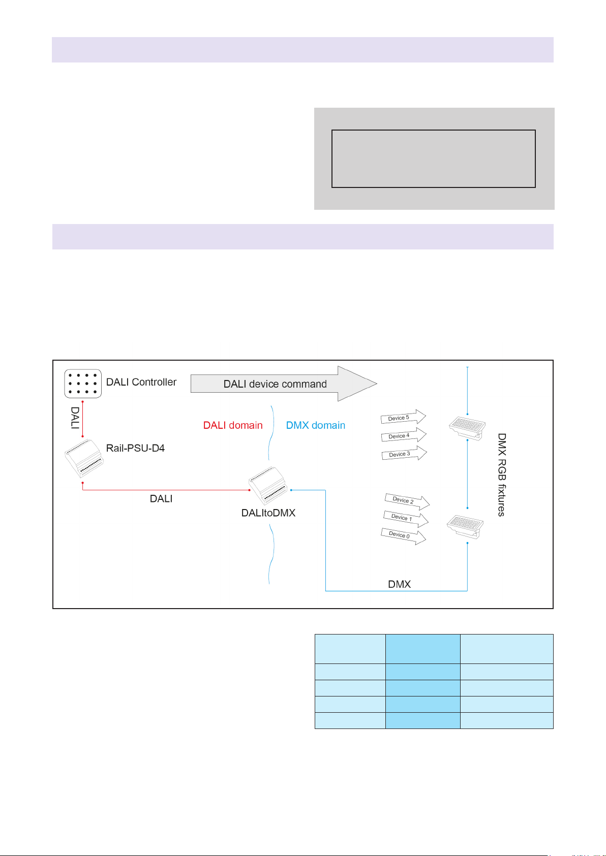
1. Scene - replay scenes stored in the
DALI devices.
2. Broadcast - all devices receive the same
command.
3. Group - each DALI device can be
assigned to any of 16 groups.
4. Device – each of the 64 possible devices
is controlled individually.
When new DALI devices are used they
must be commissioned. This requires a
DALI commissioning tool such as an Artistic
Licence Commissioner dali.

Page 10
DALItoDMX User Guide
‘B’, ‘D’ and ‘G’ refer to Broadcast, Device and Group respectively.
DALI
Command Type Details Supported in
Device Mode?
Supported in
Trigger Mode?
Good Data
LED?
999 Direct Arc Value Send direct level
values
Y
(B/D/G)
Y
(B/D/G) √
0O Send the o
command
Y
(B/D/G)
Y
(B/D/G) √
1Up Increase value by
1 until Max Level
Y
(B/D/G) N√
2Down Decrease value by 1
until Min Level
Y
(B/D/G) N√
3Step Up Increase value by
1 until Max Level
Y
(B/D/G) N√
4 Step Down Decrease value by
1 until Min Level
Y
(B/D/G) N√
5Recall Max
Level Output Max Value Y
(B/D/G) N√
6Recall Min Level Output Min Value Y
(B/D/G) N√
7Step Down and
O
Decrease value by 1/
Turn o
Y
(B/D/G) N√
8 On and Step Up Turn on /
Increase by 1
Y
(B/D/G) N√
16 - 31 Go to Scene x Go to Scene
Command
Y
(B/D/G)
Y
(see Appendix
3)
√
144 Query:
Status
Query:
Status
Part supported:
Replies: 4 hex
only when unit
power is ON
Part supported:
Replies: 4 hex
only when unit
power is ON
x
145 Query:
Device
Query:
Device Y Y x
147 Query:
Lamp Power On
Query:
Lamp Power On
Part supported:
Replies: FF hex
only when unit
power is ON
Part supported:
Replies: FF hex
only when unit
power is ON
x
151 Query:
Version Number
Replies:
Current Version Y Y x
153 Query:
Device Type
Replies:
Device Type N N x
160 Query:
Actual Level
Replies:
Current Value Y Y x
161 Query:
Max Level
Replies:
Max Value YNx
162 Query:
Min Level
Replies:
Min Value YNx
Appendix 2 - Supported DALI commands

Page 11
DALItoDMX User Guide
DALI
Command Type Details Supported in
Device Mode?
Supported in
Trigger Mode?
Good Data
LED?
163 Query:
Power On Level
Replies:
Power On Level YNx
164
Query:
System Failure
Level
Replies:
System Failure Level
Y
Replies: FE hex
Y
Replies: FE hex x
165 Query:
Fade Time
Replies:
Fade Time Y
Y
Replies “No
Fade”
x
165 Query:
Fade Rate Not implemented
Y
Replies “Not
applicable”
Y
Replies “Not
applicable”
x
176 - 191 Query:
Scene Levels
Replies:
Scene Levels YNx
192 Query:
Groups 0 to 7
Replies:
Group Assignment YNx
193 Query:
Groups 8 to 15
Replies:
Group Assignment YNx
Appendix 2 - Supported DALI commands (continued)

Page 12
DALItoDMX User Guide
Appendix 3 - Trigger Mode Mapping Tables
DALI I/P
Command
DMX
O/P
Slot
Device 1 1
Group
1 2
2 3
34
45
5 6
67
7 8
8 9
910
10 11
11 12
12 13
13 14
14 15
15 16
16 17
Scene All 18
DALI I/P
Command
DMX
O/P
Slot
Device
1 1
2 2
3 3
4 4
Group
1 5
2 6
37
4 8
59
610
711
812
913
10 14
11 15
12 16
13 17
14 18
15 19
16 20
Scene All 21
DALI I/P
Command
DMX
O/P
Slot
Device
1 1
2 2
3 3
4 4
5 5
16 16
Group
117
218
319
420
521
622
723
824
925
10 26
11 27
12 28
13 29
14 30
15 31
16 32
Scene All 33
DALI I/P
Command
DMX
O/P
Slot
Device
1 1
2 2
3 3
4 4
5 5
6 6
7 7
63 63
64 64
Group
165
266
367
468
569
670
771
872
973
10 74
11 75
12 76
13 77
14 78
15 79
16 80
Scene All 81
Table i: Mapping for
1 virtual device
Table ii: Mapping for
4 virtual devices
Table iii: Mapping for
16 virtual devices
Table iv: Mapping for
64 virtual devices
Tables (i-iv) detail the pre-programmed relationship between the virtual devices and the DMX
output slots in Trigger Mode. For all tables, the permitted DMX values for Devices and Groups
lie in the range 0-255.
DALI
Scene
DMX
Value
1 1
2 2
3 3
4 4
DALI
Scene
DMX
Value
5 5
6 6
7 7
8 8
DALI
Scene
DMX
Value
9 9
10 10
11 11
12 12
DALI
Scene
DMX
Value
13 13
14 14
15 15
16 16
Table v:
DMX values
corresponding
to individual
scene selection
Appendix 4 - Trigger Mode Scene Selection Table

DALItoDMX Specication
Mechanical
yHousing: DIN rail case
yMaterial: Polycarbonate plastic - UL94-V0
rated
yOverall dimensions: 90 mm (H) x 88 mm
(W) x 62 mm (D)
yWeight: 0.2 kg
yMounting: 35 mm DIN rail or surface
mount
yCountry of manufacture: UK
Environmental
yOperating temperature: 0°C to 40°C
yStorage temperature: -10°C to +50°C
yOperating relative humidity (max): 80%
non-condensing
yIP rating: IP20 indoor use only
yCertication: CE, WEEE, RoHS
yWarranty: 2-year (return to base)
Power & Electrical
yInput voltage: 9-24 VDC
yInput connector: (1) 2-pin screw terminal
yInput power (max): 10 W
yDC fuse: internal resettable fuse for
control electronics
DMX512 Ouput
yOutput mode: PSU referenced
yOutput ESD protection: 12 kV
yElectrocution protection: Output protected
against continuous connection to 425
VAC (self-healing)
Control
yInput Protocols: DALI (DT0)
yOutput Protocols: DMX512, DMX512
(1990), DMX512-A
Conguration
yDIP Switches - Device/Trigger mode,
virtual DALI device number (1/4/16/64),
dimming curve
Data Connections
y3-pin Screw Terminal DMX Output (1 no.)
y2-pin Screw Terminal DALI Input (1 no.)
LED Indication
yPower / Non-commission / Good data /
DALI & Bus power
Ordering Info
yProduct code: DALItoDMX
Accessories (not included)
yPSU-24-2-FER
ydaliPSU quad
yCommissioner dali
DALI Input
yInput mode: optically isolated
Page 13
DALItoDMX User Guide

Warranty
All products are covered from date of purchase
by a two-year return to base warranty.
By return to base, we mean that the customer
is responsible for all costs of transport to and
from Artistic Licence.
Returns will not be accepted without prior
authorisation. In order to discuss a request to
return goods, please email:
Sales@ArtisticLicence.com
Compliance
All Products manufactured or sold by
Artistic Licence Engineering Ltd are fully
compliant with the appropriate CE and RoHS
regulations. Product specic information is
available on request.
Waste Electrical & Electronic Equipment
(WEEE)
Artistic Licence is a member of a WEEE
compliance scheme and will happily recycle
any of our products that you, at your expense,
return to us.
CE Compliance
DALItoDMX is CE compliant when installed
in a shielded and earthed metal case
Due to our policy of continuing product improvement
specications are subject to change without notice
Artistic Licence
The Mould Making Workshop
Soby Mews
Bovey Tracey
TQ13 9JG
United Kingdom
Telephone +44 (0) 20 8863 4515
Email: Sales@ArtisticLicence.com
Web: www.ArtisticLicence.com
Support@ArtisticLicence.com
Table of contents
Other Artistic Licence Media Converter manuals
Popular Media Converter manuals by other brands

DVTEL
DVTEL EV Series Quick installation guide

Trycom Technology
Trycom Technology TRP-C39 user manual

Transition Networks
Transition Networks J/FE-CF-04 SMLC user guide

Linear Technology
Linear Technology DC2641A Demo Manual

StarTech.com
StarTech.com ET1000SM40LC installation guide

Palmer
Palmer PAN04A quick start guide