Beresford TC-7534 caiman MKIII SFW3 User manual

1
TC-7534
Caiman MKII SFW3 Instruction
Manual
Stereo Audio Digital-to-Analogue Converter
Overview
The TC-7534 Caiman MKII is a reference-quality digital-to-analogue audio
converter featuring the latest DAC Audio technology, Direct Coupled output
stage, and Class-AB headphone stage. The Caiman is designed for
maximum transparency and critical playback in professional audiophile
applications.
Burn in
Many users report that the sound output develops in quality after a few days
of use. The Caiman can be left powered on and playing a music stream with
the volume turned down for a few days to speed up the burn in process.
Fixed Output Level connection
The Caiman Fixed Output is designed to connect to the CD or AUX input of
an amplifier.
Variable Output Level connection
The Caiman Variable Output is designed to connect to the input of a power
amplifier or active speakers.
Front Panel
Digital Inputs
Four digital input connectors (1 x coaxial, 1 x USB, and 2 x optical).
Input Status Display
Five LED’s on the front panel indicate which digital input is selected and
when the Caiman is in AUTO or MANUAL mode.
Select Switch
The Select switch allows you to select between input signals.
Function Switch
The Function switch allows you to select between AUTO input signal detect,
Manual input channel selection, and LED sleep mode.
Stereo Headphone Socket
The stereo headphone socket mutes the fixed RCA/PHONO output when a
headphone plug is inserted
Headphone Amplifier
The Caiman headphone output is driven by a high-end headphone
amplifier. It is designed to drive loads between 12 to 600 Ohms.
Volume Control
The front-panel Volume Control sets the output level of the headphone.

2
.
Rear Panel
Digital Inputs
Four digital inputs, selected from the front-panel toggle switches.
The Caiman will not decode DSD, AC3, DTS, or ADAT signals.
176.4kHz sampling rate is not supported.
Input 1 – Optical
The optical input 1 is a TOSLINK connector.
Input up to 24Bit/192kHz
Input 2 – Optical
The optical input 2 is a TOSLINK connector..
Input up to 24Bit/192kHz
Input 3 - SPDIF
The coaxial input uses a RCA connector.
Input up to 24Bit/192kHz
Input 4 – USB
The USB input uses a USB B connector.
Input up to 24Bit/192kHz in shared mode
Input up to 24Bit/96kHz in exclusive mode
I2C input
The Caiman has an I2C input that is designed for future expansion. Further
information on this will be available on our website at www.beresford.me
Analogue Output
The Caiman has a Left and Right Fixed/Variable Line output, terminated
into a pair of RCA/PHONO sockets.
The output is disconnected when a headphone is plugged into the
headphone socket. In this condition the Caiman can be used as a
headphone amplifier.
DC power supply socket
The supplied external AC-DC power supply is 15Volts. The Caiman can
however work with regulated power supplies down to 12Volts. The Caiman
also supports the use of 12V rechargeable batteries or battery packs.
The centre pin is the Positive power supply terminal.
A country specific AC-DC power cord is included with each Caiman
converter shipped to most countries. Plug adapters for less well known
configurations are otherwise available locally.
The Caiman can operate from as little as 200mA, and withstand external DC
power drop out conditions for up to 2 seconds..
Ground Terminal
The Caiman has a ground terminal. This should be used for connection to
your amplifier if you are experiencing ground loop problems.
NOTICE:
The Caiman does not have a sound muting output relay.
So when using the Caiman as preamplifier, switch the Caiman ON before
your power amplifier, and switch your power amplifier OFF before the
Caiman. This is to prevent the switch off signal pulse from the Caiman
passing to your speakers.

3
Important Specification Notes
1. The audio output on the RCA/PHONO socket can be set to a fixed
or variable output via the Fixed/Variable switch on the front panel.
The variable output can be adjusted with the volume control.
2. The USB circuit is only able to play back signals up to 24 Bit/96kHz
bitrate.
3. Playback of 176.4kHz is not supported
4. The first 3mm of travel of the volume control is used to bias the
headphone amplifier circuit. So some differences in channel
balance might be noticeable within that space.
Installation
1. Connect the DC plug from the Caiman power supply to the DC
socket on the DAC.
2. Connect the power cord figure of 8 end to the Caiman power
supply.
3. Connect the DAC input sockets to your audio and video equipment
with suitable optical or digital coaxial cables. See our website for
our own list of suitable cables and conversion adapters.
4. Connect the RCA stereo output via RCA/PHONO cables to the CD
or AUX input of your amplifier via stereo RCA/PHONO cables of a
suitable length.
5. Plug the mains plug end of the Caiman power supply power cord
into a mains socket.
6. Press the Power button to switch ON the DAC.
AUTO/MANUALMode(experimental)
Press the FUNCTION button for about 1 second and let go of it as soon as
the RED STATUS LED light up. The DAC will scan each input one by one till
it finds a digital input signal. The STATUS LED and the operating input LED
will now both light up. When the input signal is removed, or the external
equipment plugged into that input is switched OFF, the DAC will start to
scan the inputs again till it finds a new valid input signal.
IMPORTANT:
The basic Auto function won’t operate with incoming digital signals that do
not switch OFF when no audio is present. Examples of this are some
satellite and cable boxes. In those cases you can try the Advanced AUTO
Mode.
MANUAL MODE
If the STATUS LED is lit and the DAC is either scanning for a new input
signal or playing music, you can switch to manual mode by pressing the
FUNCTION button once. The STATUS LED should now be OFF.
To select an input, press and release the SELECT button.
SOUND SIGNATURE MODE
The Caiman MKII with the SFW3 firmware is capable of four different modes
of audio data processing. To change between sound signatures and modes,
press and hold down the SELECT button for about two seconds. Release
the SELECT button as soon as the RED STATUS LED lights up. The
firmware will now automatically switch to the next data processing option.
One LED blink = Mode-1 = standard XTAL data retrieval and processing
Two LED blinks = Mode-2 = optimized XTAL processing
Three LED blinks = Mode-3 = DATA recovered clock processing mode
Four LED blinks = Mode-4 = PLL clock processing mode
NOTE: In mode 3 & 4 the clock might not be able to find the exact beginning
of an audio track when you first switch on the DAC or change to playing files

4
of a different sampling rate. You can correct that by temporarily selecting
mode 1 or 2 so that the clock gets back its bearings.
SLEEPMODE
Make sure that the STATUS LED is OFF when setting the SLEEP mode
function. If the STATUS LED is not OFF, press and release the FUNCTION
button once to switch the STATUS LED OFF.
Press and hold down the FUNCTION button until the STATUS LED blinks.
This will activate the SLEEP MODE function. To cancel the SLEEP mode,
repeat the same procedure.
In SLEEP MODE each LED will be off when a valid audio stream is
detected. The selected input LED will light up again if no audio is detected.
ProgramBackup
When you switch the DAC OFF your settings will be saved. So next time you
switch the DAC back ON your DAC will start using your saved settings.
RESET MODE
The DAC’s operating system might get confused on occasions and refuse to
operate correctly when the buttons are pressed. If that happens you need to
reboot the MCU (Micro Control Unit) to restore the DAC to the factory
default mode.
1. Switch the DAC OFF via the Power button.
2. Wait at least twenty seconds.
3. Switch the DAC back ON via the Power button.
4. Whilst the LEDs are each lighting up one by one, press and hold
down the SELECT button.
5. When all the LEDs are lit up, let go of the SELECT button.
Fuse Holder
The fuse holder is inside the case close to the DC power connector socket.
The fuse rating is 2 Amps.
Safety Information
The factory supplied AC/DC adapter is suitable for 90 to 270 Volts AC
operation.
Repairs
Do not service or repair this product unless properly qualified.
Fuses
For continued fire hazard protection always replace the internal fuse with
the correct size and type.
Modifications
Do not substitute parts or make any modifications that may create safety
hazards and void the warranty.
Notes on Warranty Repairs
An RN (Returns Number) is required when sending products back. Goods
for repair must be shipped to Beresford ME prepaid and preferably in their
original shipping carton with the RN clearly visible on the exterior of the
packaging. A note should be included giving detailed reasons for the return.
This manual suits for next models
1
Table of contents
Other Beresford Media Converter manuals

Beresford
Beresford ASYNCH-1 User manual

Beresford
Beresford TC-7510 MK6 User manual
Beresford
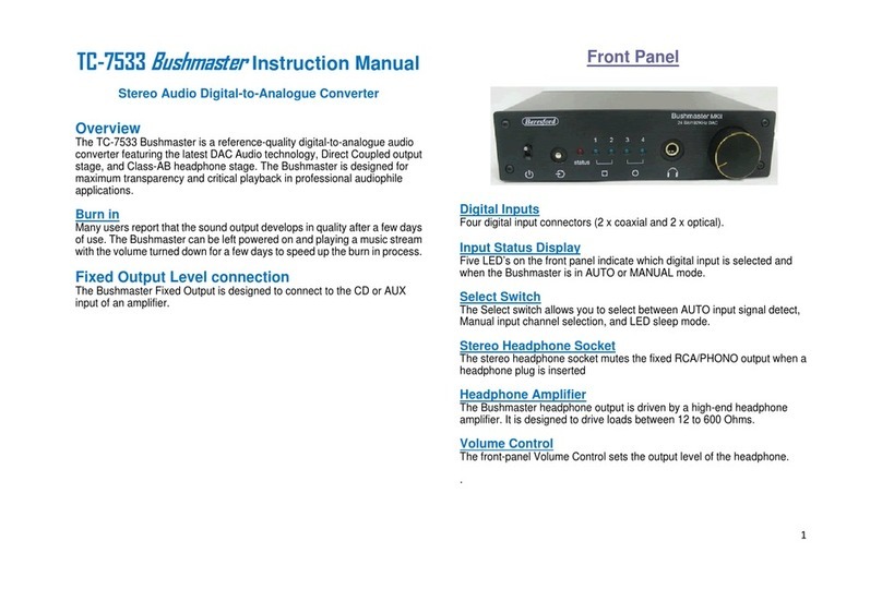
Beresford TC-7533 Bushmaster User manual

Beresford
Beresford Bushmaster MKI User manual

Beresford
Beresford Caiman SEG-22 User manual
Beresford
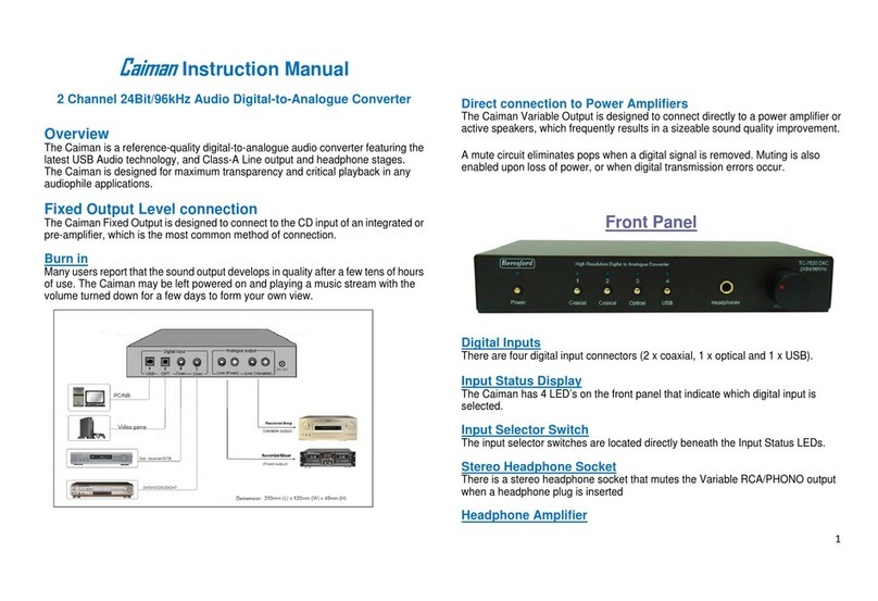
Beresford 2 Channel 24Bit/96kHz Audio Digital-to-Analogue... User manual

Beresford
Beresford TC-7535 Caiman SEG User manual
Popular Media Converter manuals by other brands
Absolute Process Instruments
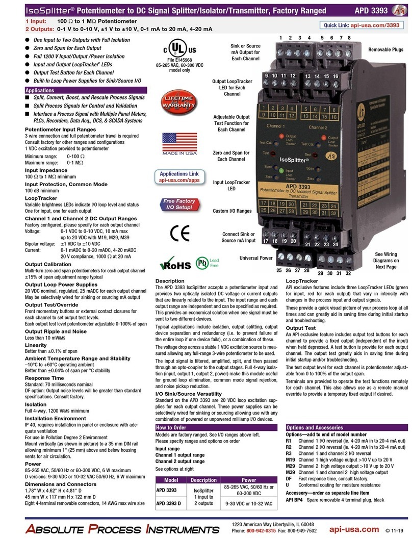
Absolute Process Instruments IsoSplitter APD 3393 quick start guide
Encoder
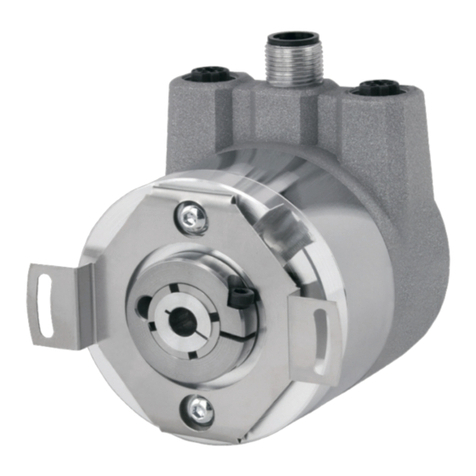
Encoder A58HE Technical reference manual
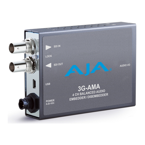
AJA
AJA 3G-AMA Installation and operation guide
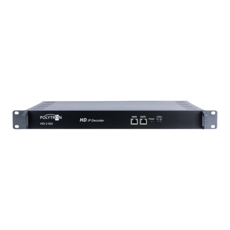
Polytron
Polytron HDI 2 SDI user manual
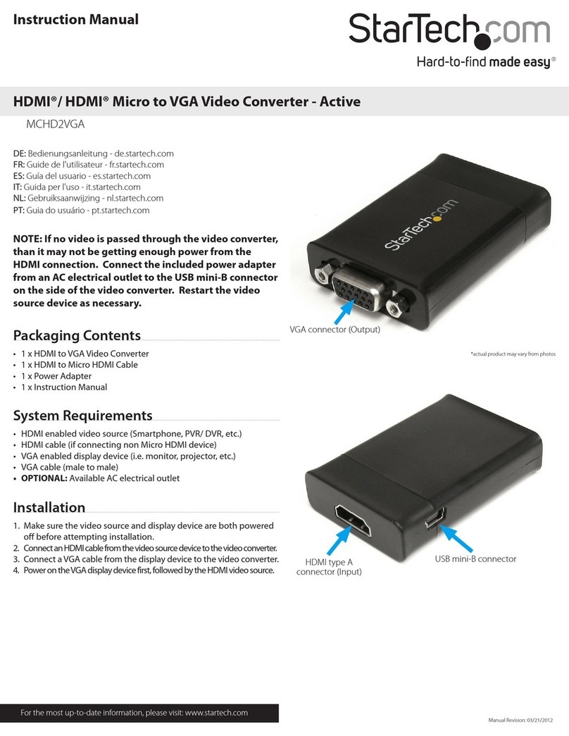
StarTech.com
StarTech.com MCHD2VGA instruction manual

Ascent
Ascent IRD1560 user manual
