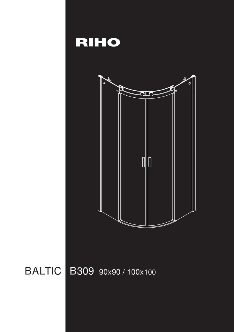
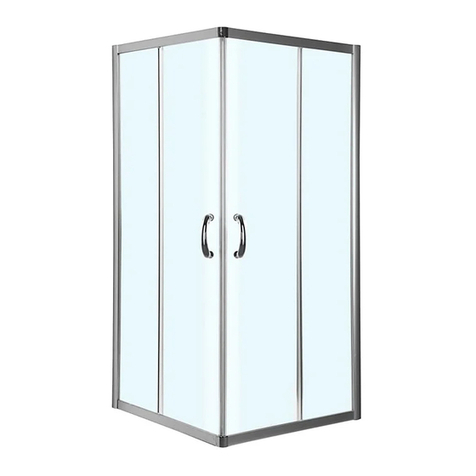
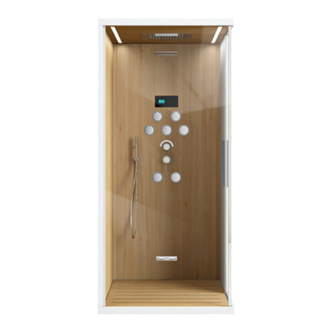
Artize QUADRO Safety guide

Manual for Installation
Steam Shower Cabin
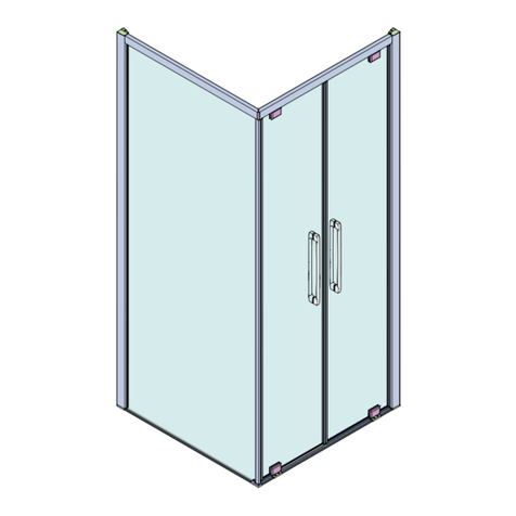
QUADRO - 120 X 100

* Images shown are for illustration purpose only.
Actual product may vary due to product enhancements.

• Safety Instruction & Precaution 01 & 02
• Tools 03
• Overall Dimensions 04
• Site Preparation & Installation Requirement 05
• Part Identification Reference 06
• The Cabin Base / Shower Tray Setting on Finished Floor Step 1 07
• Shower Wall Fixing on Base Tray Step 2 08
• Fixing the Drain Connection 09
•
Side Wall Fixing Step 3 10
•
Side Wall Fixing Step 4 11
•
Roof Panel Fixing Step 5 12
• Installing Glass Walls & Fixing Cabin Door Step 6 13
•
Electric & Plumbing Connections 14
•
Main Power Connections 15
• Faucet Mixer Features & Maintenance 16
• Steam Keypad 17
• Keyboard 18
• Settings 18
•
Steam Bath 19 & 20
• Choromotherapy 20
• Music Function 21
• Bluetooth 21
• Functions 22
• Alarm 22
• Aroma 22
• Boiler Maintenance 23
• Warranty 24
• Standard Packing Information 25
• Notes 26 & 27
Content

01
Caution
Product must be installed by the qualified person. The manufacturer declines all liability for events arising
from incorrect installation or operation of the tub. The product is designed for indoor use in bathrooms, and
must not be installed in the open. Always power off the product (Omnipolar switch in the OFF position)
when maintenance is to be performed on electrical components.
Electric safety
Product must be fixed securely and connected sturdily to the mains and the earthing and unipotential systems.
The manufacturer accepts no liability if the hydraulic and electrical circuits are not in compliance with
EN safety standards. The building’s electrical circuit must be in compliance with EN safety standards and
protected by a standards-approved differential switch (safety cut-out) with a differential value of 30mA.
The connection to the electrical mains must be permanent and made with a cable that is not lighter than type
of 3x2.5mm2. It must be intercepted by an Omnipolar switch with an opening of contacts of at least 230V
and a current of 16A. It should if possible be located outside the room and distant from locations where it
might come into contact with water.
Connecting the equipotential circuit
Provide equipotential connection of the metallic masses extraneous to the shower booth by using the earth
equipotential contact. Arrange the cable outlet near the electrical power supply.
Safety rules for bathroom
Sockets, lights, switches, and other electric devices must be installed outside the danger zones as laidout
by the laws and international standards for bathrooms. It is strictly prohibited to touch, handle, or switch on
electric appliances while using the shower booth.
Electrical appliances positioned in the zones surrounding the shower box must be securely fixed in position
to prevent them from falling into the shower box.
Safety Instruction & Precaution

02
225 cm
60 cm
60 cm
240 cm
240 cm
3
2
1
02
3
Precautions
The material used for the construction of the shower booth is extremely tough and durable, which is
demonstrated by the widespread use of this material in many industries.
However, this material may be damaged by certain chemical substances such as acetones and
solvents in general and stained by alcohol-based liquids if these are not removed immediately.
For this reason, it is advisable to protect the product surface with paper or cardboard (the packing
cartons may also be used) during installation, in order to ensure that no abrasive substances or paint
come into the surface. It is also advisable to avoid placing tools on the surface of the shower plate.
Immediately on delivery, check that the appliance is in perfect condition and that the packaging is
not damaged in any way.
Safety distances
Shower areas, saunas, bathrooms, swimming pools, and the surrounding areas are classified by EN safety
standards as special zones since the humidity and dampness associated with these areas can make them
extremely dangerous.
The standards specify four clearly defined areas: zone 0,1,2 and 3. The Omnipolar switch with an opening
of contacts of at least 3.5mm must be located outside of these zones, distant from possible contact with water.
The limits of the various danger zones may be modified by the presence of walls, protective panels, and
fixed insulating walls which limit access to the tub or to the shower plate. In this case, the area is delimited
by taking a piece of string whose length is that of the area and winding it around the wall to the opposite
side. The path taken by the end of the string marks the danger zone. The zone that is external to the four
danger areas is considered to be normal.
Important
Consult the technical data sheet of the shower cabin to be installed. We suggest the installation of a 100-micron
feed water filter and a water softener. Before positioning the shower box, it is the duty of whoever assembles
the product to check that all the connections are watertight.
Safety Instruction & Precaution
* Recommendation : Two person & standard tool kit required for product installation.
Tools
Ø6
Ø3
03

120
100
222
Overall Dimensions
Technical specification for 120 x 100
Gross weight 240 KG
Electrical & plumbing requirements
Required socket dimensions for drainage flex pipe (inner dia) ø50mm
Required length for flex pipe for drainage 400-800mm
Socket dimensions for water inlet (hot / cold) 1 / 2”
Inlet water pressure 2.5Bar-3.5Bar (300kpa)
Input voltage 220-240V
Frequency 50HZ
Power load 4.6KW
Product features
Steamer 4.5KW
Multi function head shower Rain + Mist
Cascade waterfall 1 pcs
Number of body jets (fixed) 6 pcs
Handshower 1 pcs
Chromotherapy RGB-LED
Bluetooth
Music / Speaker 2 pcs
Digital touch control 1
04

Site Preparation & Installation Requirement
* All dimensions in mm.
C.P : Electrical connection points (1.5mtr open wire).
C1 / F1 : Hot / cold water connection.
O1 : Drain point connection.
200
2000
950
90
100
100
100
500
Front wall
150
50
Entry / Door
05

1. Part Identification Reference
Over head
shower
Display /
Keypad
Body jets
Glass door
Diverter mixer
Shower tray
Drain waste
Steam dispenser
Wall outlet with
hand shower
Roof
Sitting bench
D’Scale
06

07
82mm
2. The Cabin Base / Shower Tray Setting
on Finished Floor Step 1

3. Shower Wall Fixing on Base Tray Step 2
* Use L clamp & screws to fix the cabin walls.
08

* The drain connection pipe is not a part of product kit.
Ø50
09
4. Fixing the Drain Connection

* Front wall installation & fixing.
5. Side Wall Fixing Step 3
10

* Fix adjoining side walls using nut & bolt.
6. Side Wall Fixing Step 4
11

* Fix the shower roof using metal L clamps.
7. Roof Panel Fixing Step 5
* Two persons are required to install cabin/door roof.
12

8. Installing Glass Walls &
Fixing Cabin Door Step 6
* Cover the shower tray from front / side using ACP slit cover.
13
I J K L
x2 x2 x2x4

Electric & Plumbing Connections
* Make a proper earth connection for body grounding,
is an efficient way of protecting the appliances from electrical hazard.
Audio
LED
AUX
Display
Water
14

* Check water the water supply before plumbing connection
& water supply should be clean / debris free.
Ø1/2”
Ø1/2”
OK
230Vac
50Hz
230Vac
50Hz
L
N
Main Power Connections
15

Functions :
• When the knob points to the ‘OFF’ position, there is
no water supply from outlets
• When the knob points to position “I”, the Outlet line-I
release water supply
• When the knob points to position “II”, the Outlet line-II
release water supply. As well as in knob position "III",
"IV" and position "V"
• When the knob points in between positions “I” & “II”,
the Outlet lines-I & II release water supply
• When the knob points in between positions “II” & “III”,
the Outlet lines-II & III release water supply
• When the knob points in between positions “III” & “IV”,
the Outlet lines-III & IV release water supply
Maintenance & troubleshooting
Following the below guidelines may be helpful in preserving the look of your newly acquired faucet
1. Chrome surfaces may get damaged by acids, detergents, disinfectants, and metallic cleaning pads.
2. For lime scale or stain removal usage of ‘GLITZ’ cleaning solution is beneficial.
Safety lock
Thermostatic valve
(Handle)
Diverter handle
Wall flange
38°
I
II III
IV
off
Faucet Mixer Features & Maintenance
Water temperature regulation
Thermatik mixer controls the temperature of the outlet irrespective of the temperature of the water
coming in the hot inlet from boilers / geyser.
For Example: If the temperature of hot inlet varies from 40°C to 60°C or vice-versa the temperature
of the outlet water will still remain the same as set by the end user.
Anti-Scald Function
Under the condition of the cold water supply getting cut off and only the hot water supply is available.
The thermatik mixer saves the person from burning by blocking the hot water supply.
Child / Safety Lock
The safety lock on the handle ensures the person does not get burned even due to an accident,
since to attain a temperature greater than 38°C, the safety lock has to be pressed and the handle
turned anti-clockwise simultaneously.
16

Steam Keypad
Features :
The keypad feature “Touch screen” technology to control 6 functions :
• ON / OFF • Alarm • Steam bath
• Chromotherapy • Stereo FM radio • Bluetooth
N.B.
In the “TOP” version, the function (with the related symbol)
is replaced by the “Whirlpool shower” function.
Illuminated ring :
Increases and decreases the “Values” of the functions. Simply slide
a finger inside and move it clockwise or anti-clockwise.
RGB
OK
On / Off
Alarm
Display
Radio
Bluetooth
Chromotherapy
Steam bath
Illuminated
ring increase
and decrease Confirmation
17
Table of contents