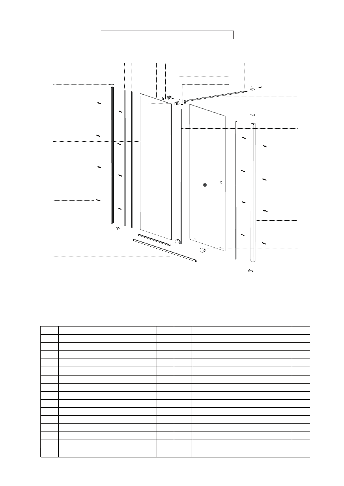
Aquadart Rolla 8 User manual

Note: This instruction shows the installation process for all of our Rolla 8 configurations, please check below
which pages are relevant to your configuration before commencing work:
INSTALLATION INSTRUCTIONS www.aquadart.co.uk
Drill 6mm Masonry Drill
2.75mm HSS Drill
Spirit Level
Sealant Gun
Tape Measure
PH2 TYPE
Screwdriver
Pencil
Hex Wrench
Tools Required
Please note hand tools NOT supplied
This product should be installed by a suitably qualified and proficient person. The fitting instructions should be
followed carefully to ensure a proper and safe installation. Failure to follow these instructions could result in future
injury.
These instructions and list of parts assume that installation is done against solid/tiled walls.
Please check this product for damage prior to starting the installation. No claims can be made after the product has
been fitted.
PLEASE NOTE :The minimum and maximum adjustment sizes noted on the product brochures are based on
perfectly plumb walls and trays.
SLIDING WETROOM, ENCLOSURE & DOOR
1
Sliding Wetroom refer to pages 1-8 • Sliding Door Recess refer to pages 9-15 and page 25
Sliding Door Enclosure refer to pages 16-24 and page 26 • Aftercare refer to page 27

Box Contents
COMPONENTS AND BOX CONTENTS
1
2
3
4
56
7
9
8
10
11
13
12
14
15
16
17
22
21
20
19
18
27
26
25
242331 30 29 28
33
32
No. Description Qty No. Description Qty
1 Wall Profile Top Cap 2 18 Bottom Rail End Fixing Screw Cap 1
2 Wall Profile 1 19 Roller Set 2
3 Fixed Panel 1 20 Handle 1
4 Door Panel 1 21 Support Arm Wall Fixing 1
5 Closing Bubble Seal 1 22 ST Screw 4x30 1
6 Fixed Panel Fixing Seal 1 23 Allen Grub Screw M5x6 1
7 Vertical Seal(Optional) 1 24 Wall Plug 1
8 Wall Plug 4 25 Glass Clamp 1
9 ST Screw 4x30 4 26 Grub Screw M5x6 1
10 Bottom Rail End Cap (L/R) 2 27 Grub Screw M10 x 6 1
11 Bottom Strip 1 28 Soft Head 1
12 Bottom Rail 1 29 Grub Screw M10 x6 1
13 Bottom Strip End Cap 1 30 Stopper Screw Cover 1
14 Bottom Rail End Fixing Soft Head 1 31 Roller Stopper(L/R) 2
15 Wall Plug 1 32 Support Arm Tube 1
16 Bottom Rail End Fixing(L/R) 2 33 Glass Clamp Screw Cap 1
17 ST Screw 4x40 1
SLIDING WETROOM INSTRUCTION
2

IMPORTANT - Missing Components
Please check this product for missing components prior to installation.
For spare parts visit www.aquadart.co.uk
IMPORTANT - Installation site
1. Ensure the top surface of the shower tray on which the enclosure will be installed is level in every direction.
2. The tiles or other wall finishing should be effectively sealed at tray edges.
3. Tiles should extend at least to the corner of the tray and a minimum of 2.0 meters from the top of the tray.
FIXING KIT COMPONENTS, SITE CONDITIONS
SLIDING WETROOM
FIXING KIT
Wall Profile Top Cap
x1
Bottom Strip End Cap
L/R x1
Handle
x1
Wall Plug
x6
Screw ST 4X30
x5
Cover Cap
x1
Support Arm x1
Roller
x2
Bottom Strip End
Fixing x1
Bar x1
Support arm glass clamp x1
Wall Fixing x1
Allen Screw M5 x1
Allen Screw M10 x1
Fixed panel Fixing
Seal x1
Roller Stopper
Cover Cap
x1
Glass Clamp Cover Cap x1
Roller Stopper L/R
x1
Soft head
x1
Closing Bubble Seal
x1
Screw ST 4X40
x1
3

1.1
Step 1.1 Fit the Bottom Rail End Cap L/R (Part 10) on the wall profile (Part 2) from the bottom. Place the Wall Profile onto
the tray, roughly 10mm away from the front edge of the end cap. Level the Wall Profile using a spirit level then
mark the profile through the pre-drill holes on the Wall Profile. (Diagram 1.1).
Note: Ensure the channel with the pre-drill holes is facing outwards when placing the Wall Profile onto the tray.
Step 1.2 Remove the wall profile and drill the marked points using a 6mm masonry drill bit.(Diagram 1.2)
Step 1.3 Insert wall plugs(Part 8) then secure the wall profile onto the wall using ST4X30 screws x4 (Part 9)(Diagram 1.3)
10mm
1.2 1.3
Note:
The product can be constructed either way up, for left or right hand opening.This instruction is showing a Left
hand opening
dnaHtfeL
dnaHthgiR
4

Step 2.1 Carefully lift the fixed panel (Part 3) and insert into the wall Profile groove,it allows 0-20mm for the adjustment.
Once the fixed panel is in required adjustment, place the bottom strip(Part 11) onto the tray and mark a line
onto the profile. Cut the profile through the marked line to get required length.(Diagram 2.1)
Fixed Panel/Face Inside
0-20mm adjustment
2.1
Step 2.2 Remove the fixed panel then replace the bottom strip (Part 11) onto the tray, ensure the bottom strip groove is
level to the wall profile groove on the inside face (Diagram 2.2A). Mark the line on the tray for the bottom strip
position once you have ensured it is straight. (Diagram 2.2B)
Level
Straight
2.2B
Step 2.3 Drop the silicone sealant onto the bottom side of the bottom strip,take the 3M adhesive tape back away then
carefully place it onto the tray against the marked line.(Diagram 2.3)
2.3
Step 2.4 Drop the silicone sealant into the groove of the bottom strip(Diagram 2.4) then carefully lift the fixed panel
and insert it into the bottom strip then push it onto the wall profile.After the fixed panel has been placed at the
required position insert the fixing seal from top to bottom to secure the fixed panel onto the wall profile.
(Diagram 2.5)
INSIDE
Outside
Inside
2.4
2.5
2.2A
5

Step 3.2 Ensure the bottom rail is level and straight then secure it onto the tray using the bottom rail end fixing(Part 16)
and screw ST4x40(part 17).Then insert the black soft head into the hole on the bottom rail end fixing(Diagram 3.2)
Step 3.3 Assemble the bottom rollers onto the door panel.Ensure the gasket has been used on both faces of the glass.
3.1
3.2
Step 3.4 Carefully lift the door panel and assemble onto the bottom rail, fit the glass clamp(Part 25) to hold the fixed
panel and door panel in place.
IMPORTANT:TURN THE ROLLER BODY TO ENSURE THE EDGE OF THE CUT ON THE ROLLER BOTTOM DOES
NOT TOUCH BOTTOM RAIL TOP SURFACE BEFORE SLIDING THE DOOR PANEL
3.3
3.4
Step 3.5 Adjust the roller to raise or lower the door panel to ensure it does not touch the ground or tray(Diagram 3.5),
also ensure that the overlap of the fixed panel and door panel is equal at the top and the bottom.Slide the door
panel to ensure it’s running smoothly.
Tips:If the door panel does not run smoothly please check that the bottom rail is 100% straight,and check that the
wall profile is 100% level.
3.5
IMPORTANT
Step 3.1 Insert the bottom rail (Part 12) into the end cap (Part 10) (Diagram 3.1).
6

10mm
Door panel
Fixed panel
3.6
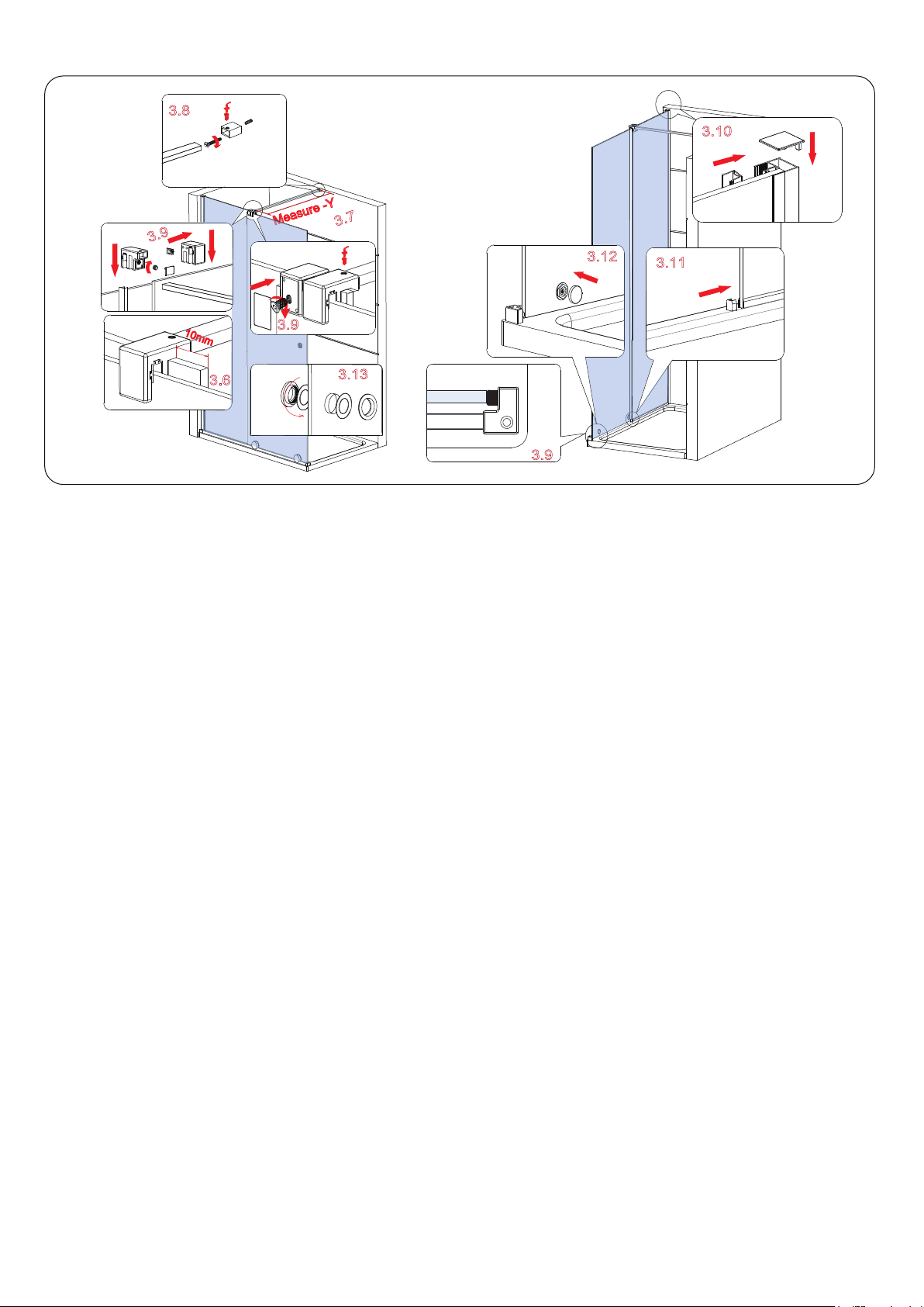
Step 3.6 Ensure the glass clamp is in about 10mm away from the fixed panel edge(Diagram 3.6) then attach it onto the
fixed panel using M10 x6 grub screw(Part 27)
Step 3.7 Fit the support arm wall fixing onto the support arm bar and place it onto the wall in required position.Measure
the dimension from the glass clamp to the wall fixing to get dimension Y.Cut the support arm to the required length
X according to the formula X=(L-Y)+25mm(L is the original length of the support arm bar,1057mm)
3.7
Step 3.8 Fit the support arm wall fixing onto the support arm bar before inserting the support arm bar onto the glass clamp,
move the wall fixing to the wall and level the support arm bar, mark the postion of the wall fixing onto the wall.Drill
through the marked position on the wall using a 6mm masonry drill bit and insert the wall plug(part 24).Fix the
wall fixing onto the wall using screw ST 4X30(Diagram 3.8).
Insert the support arm bar to the wall fixing,pull the bar out from the wall fixing to insert into the glass clamp, then
secure the support arm bar together with the glass clamp and wall fixing using M5 x6 grub screws.
3.8
Step 3.9
3.9
3.9
3.9
Step 3.10 Press the closing bubble seal (Part 5) into the wall profile channel, then fit the wall profile top cap(part 1) onto the
wall profile(part 2)
Fit a soft head (part 28) onto the roller stopper (part 31),then slide the door panel to ensure it touches the soft
head on the bottom rail end fixing (Diagram 3.9), fit the roller stopper onto the door panel, ensure the soft head
on the roller stopper touches the glass clamp then secure the roller stopper onto the door panel using M10x6
grub screw (Diagram 3.9).
Door panel
3.10
3.11
3.12
3.13
Step 3.11 Fit the bottom strip end cap(part 13) onto the bottom strip.(Diagram 3.11)
Step 3.12 Press the roller screw cap to cover the screws (Diagram 3.12).
Step 3.13 Fit the ring handle(part 20) onto the door panel. (Diagram 3.13).
Step 3.14 Fit the cover cap onto the roller stopper and glass clamp.
7

Step 3.15
24 HRS
DO NOT USE THE
ENCLOSURE FOR
24 HOURS AFTER
SEALING
Applying Silicone Sealant
Sealing Inside
Seal from the top of the wall profile to the bottom on the INSIDE
between the wall profile and the wall.
IMPORTANT: Do not apply sealant on inside of the tray.
Sealing Outside
Seal from the top of the wall profile to the bottom between the
wall profile and tiles on both sides. Also seal along the bottom
where the frame meets the tray. Seal the joints between the
bottom profile and any upright profiles.
We do not recommend fitting the vertical seal (Part 7 ) onto the fixed panel as the overlap between the fixed panel
and door panel will be sufficient to avoid any leaks.If you do decide to fit vertical seal please ensure you cut it as
detailed in diagram 3.15. to avoid any obstruction to the handle or rollers.
Step 3.16 Fit the wall profile top cap( Part 1) onto the wall profile.
Step 3.15-Cut the seal
8

Box Contents
COMPONENTS AND BOX CONTENTS
1
2
3
4
56
7
8
9
10
11
13
12
17
16
15
14
22
21
20
191826 25 24 23
28
27
No. Description Qty No. Description Qty
1 Wall Profile Top Cap 2
1
2 Fixed Panel Wall Profile 2
Roller Set
1
3 Fixed Panel 1
Handle
1
4 Door Panel 1
Support Arm Wall Fixing
1
5Closing
Seal 2
ST Screw 4x30
1
6Fixed Panel Fixing Seal 1
Allen Grub Screw M5x6
1
7Vertical Seal(Optional) 1
Wall Plug
1
8Wall Plug 8
Glass Clamp
1
9ST Screw 4x30 8
Grub Screw M5x6
1
10 Bottom Rail End Cap (L/R) 2
Grub Screw M10 x 6
1
11 Bottom Strip 1
Soft Head
1
12Bottom Rail 1
Grub Screw M10 x6
1
13 Bottom Strip End Cap 1
Stopper Screw Cover
1
14 2
Roller Stopper(L/R)
Support Arm Tube
Glass Clamp Screw Cap
18
19
20
21
22
23
24
25
26
27
28
15
16
17
29
29 Closing wall profile 1
1
SLIDING DOOR INSTRUCTION
9

IMPORTANT - Missing Components
Please check this product for missing components prior to installation.
For spare parts visit www.aquadart.co.uk
IMPORTANT - Installation site
1. Ensure the top surface of the shower tray on which the enclosure will be installed is level in every direction.
2. The tiles or other wall finishing should be effectively sealed at tray edges.
3. Tiles should extend at least to the corner of the tray and a minimum of 2.0 meters from the top of the tray.
FIXING KIT COMPONENTS, SITE CONDITIONS
SLIDING DOOR
FIXING KIT
Wall Profile Top Cap
x1
Bottom Strip End Cap
L/R x2
Handle
x1
Wall Plug
x7
Screw ST 4X30
x9
Support Arm x1
Roller
x2
Bar x1
Support arm glass clamp x1
Wall Fixing x1
Allen Screw M5 x1
Allen Screw M10 x1
Fixed panel Fixing Seal
x1
Roller Stopper
Cover Cap
x1
Glass Clamp Cover Cap x1
Roller Stopper L/R
x1
Soft head
x1
Closing Bubble Seal
x2
10

Note:
The product can be constructed either way up, for left or right hand opening.This instruction is showing a Left
hand opening.IMPORTANT:if you are fitting the optional closing seal please refer to the steps on page 25.
dnaHtfeL
dnaHthgiR
10mm
Step 1.1 Fit the Bottom Rail End Cap L/R (Part 10) on the fixed panel wall profile (Part 2) and closing wall profile(Part 29)
from the bottom. Place the wall profiles onto they tray,rough 10mm away from the front edge of the end cap.
Level the wall profiles using a spirit level then mark the profile through the pre-drill holes on the wall profiles.
(Diagram 1.1)
Step 1.2 Remove the wall profiles and drill the marked points using a 6mm masonry drill bit.(Diagram 1.2)
Step 1.3 Insert wall plugs(Part 8) then secure the fixed panel wall profile onto the wall using ST4X30 screws x4
(Part 9)(Diagram 1.3)
1.1 1.2 1.3
Note: Ensure the channel with the pre-drill holes is facing outwards when placing the Wall Profile onto the tray.
11

Step 2.2 Press the bottom strip end cap R(part 10) onto the closing profile (part 29),then sit the closing wall profile
onto the bottom rail against the holes drilled on the wall.Secure the closing wall profile onto the wall using
ST 4x30 screws x4(Part 9).
2.1
Step 2.1 Insert the bottom rail into the end cap L(Part 10) fitted on the fixed panel wall profile
(Diagram 2.1)
Inside
2.2
Level
Straight
2.4B
2.5
INSIDE
2.6A
2.6B
2.4A
Step 2.4 Remove the fixed panel then replace the bottom strip (Part 11) onto the tray, ensure the bottom strip groove is
level to the wall profile groove on the inside face (Diagram 2.4A). Mark the line on the tray for the bottom strip
position once you have ensured it is straight. (Diagram 2.4B)
Step 2.5 Drop the silicone sealant onto the bottom side of the bottom strip,take the 3M adhesive tape back away then
carefully place it onto the tray against the marked line.(Diagram 2.5)
Step 2.6 Drop the silicone sealant into the groove of the bottom strip(Diagram 2.6A) then carefully lift the fixed panel
and insert it into the bottom strip then push it onto the fixed panel wall profile.After the fixed panel has been
placed at the required position insert the fixing seal from top to bottom to secure the fixed panel onto the
wall profile (Diagram 2.6B).
2.3
0-20mm adjustment
Outside
Step 2.3 Carefully lift the fixed panel (Part 3) and insert into the wall Profile groove,it allows 0-20mm for the adjustment.
Once the fixed panel is in required adjustment, place the bottom strip(Part 11) onto the tray and mark a line
onto the profile. Cut the profile through the marked line to get required length.(Diagram 2.3)
2.3
INSIDE
12

Step 3.1 Assemble the bottom rollers onto the door panel.Ensure the gasket
has been used on both faces of the glass.
Step 3.2 Carefully lift the door panel and assemble onto the bottom rail, fit
the glass clamp((part 20) to hold the fixed panel and door panel in
place.
IMPORTANT:TURN THE ROLLER BODY TO ENSURE THE EDGE
OF THE CUT ON THE ROLLER BOTTOM DOES NOT TOUCH BOTTOM
RAIL TOP SURFACE BEFORE SLIDING THE DOOR PANEL.
3.1
3.2
Step 3.3 Adjust the roller to raise or lower the door panel to ensure it does not touch the ground or tray(Diagram 3.3),
also ensure that the overlap of the fixed panel and door panel is equal at the top and the bottom.Slide the door
panel to ensure it’s running smoothly.
Tips:If the door panel does not run smoothly please check that the bottom rail is 100% straight,and check that the
wall profile is 100% level.
3.3
IMPORTANT
13

10mm
Door panel
Fixed panel
Step 3.4 Ensure the glass clamp is in about 10mm away from the fixed panel edge(Diagram 3.4) then attach it onto the
fixed panel using M10 x6 grub screw(Part 24)
Step 3.5 Fit the support arm wall fixing onto the support arm bar and place it onto the wall in required position.Measure
the dimension from the glass clamp to the wall fixing to get dimension Y.Cut the support arm to the required length
X according to the formula X=(L-Y)+25mm(L is the original length of the support arm bar,1057mm)
Step 3.6 Fit the support arm wall fixing onto the support arm bar before inserting the support arm bar onto the glass clamp,
move the wall fixing to the wall and level the support arm bar, mark the postion of the wall fixing onto the wall.Drill
through the marked position on the wall using a 6mm masonry drill bit and insert the wall plug(part 19).Fix the
wall fixing onto the wall using screw ST 4X30(Diagram 3.6).
Insert the support arm bar to the wall fixing,pull the bar out from the wall fixing to insert into the glass clamp, then
secure the support arm bar together with the glass clamp and wall fixing using M5 x6 grub screws.
Step 3.7
Step 3.8 Press the closing seal (Part 5) into the fixed panel wall profile and closing wall profile,then fit the wall profile top caps
(Diagram 3.8)
Fit a soft head (part 23) onto the roller stopper (part 26),then slide the door panel to ensure it runs into the closing
wall profile fully,fit the roller stopper onto the door panel, ensure the soft head on the roller stopper touches the
glass clamp then secure the roller stopper onto the door panel using M10x6 grub screw(Diagram 3.7)
Step 3.9 Fit the bottom strip end cap(part 13) onto the bottom strip.(Diagram 3.9)
Step 3.10 Press the roller screw cap to cover the screws (Diagram 3.10).
Step 3.11 Fit the ring handle(part 15) onto the door panel. (Diagram 3.11).
Step 3.12 Fit the cover cap onto the roller stopper and glass clamp.
3.5
3.4
3.6
3.7
3.7
3.8
3.9
3.10
3.11
14

Step 3.13
24 HRS
DO NOT USE THE
ENCLOSURE FOR
24 HOURS AFTER
SEALING
Applying Silicone Sealant
Sealing Inside
Seal from the top of the wall profile to the bottom on the INSIDE
between the wall profile and the wall.
IMPORTANT: Do not apply sealant on inside of the tray.
Sealing Outside
Seal from the top of the wall profile to the bottom between the
wall profile and tiles on both sides. Also seal along the bottom
where the frame meets the tray. Seal the joints between the
bottom profile and any upright profiles.
We do not recommend fitting the vertical seal (Part 7 ) onto the fixed panel as the overlap between the fixed panel
and door panel will be sufficient to avoid any leaks.If you do decide to fit vertical seal please ensure you cut it as
detailed in diagram 3.15. to avoid any obstruction to the handle or rollers.
Step 3.13-Cut the seal
15

Box Contents
COMPONENTS AND BOX CONTENTS
2
3
5
6
9
8
10
11
13
12
20
19
18
27
16
25 24 23 22
No. Description Qty No. Description Qty
1 Wall Profile Top Cap 2
18 1
2 Wall Profile 2
19 1
3 Fixed Panel 1
20
Handle
1
4 Door Panel 1
21
Support Arm Wall Fixing
1
5Closing
Seal 1
22
1
6Fixed Panel Fixing Seal 1
23
Allen Grub Screw M5x6
1
7 Vertical Seal(Optional) 1
24
1
8 Wall Plug 10
25
Glass Clamp
1
9 ST Screw 4x30 10
26
Grub Screw M5x6
1
10 Bottom Rail End Cap (L/R) 2
27
Grub Screw M10 x 6
1
11 Bottom Strip 1
28
Soft Head
1
12 Bottom Rail 1
29
Grub Screw M10 x6
1
13 Bottom Strip End Cap 1
30
Stopper Screw Cover
1
14 2
31
Roller Stopper(L/R)
2
15 1
32
Support Arm Tube
1
16 1
33
Glass Clamp Screw Cap
1
17 1
21
1
4
7
Roller Set
17
26
28
30
29
31
32
33
34
15
14
35
36
37
1
1
34
35
36
37
Side Panel Glass
Side Panel Bottom Fixing
Side Panel Wall Profile
T Piece
Support Arm Tube
Glass Clamp(Side Panel)
Bubble Seal
Allen Grub Screw M5x6
Grub Screw M10 x6
Glass Clamp (Side Panel) Screw Cap
Round Cover Cap 1
1
SLIDING ENCLOSURE INSTRUCTION
16

IMPORTANT - Missing Components
Please check this product for missing components prior to installation.
For spare parts visit www.aquadart.co.uk
IMPORTANT - Installation site
1. Ensure the top surface of the shower tray on which the enclosure will be installed is level in every direction.
2. The tiles or other wall finishing should be effectively sealed at tray edges.
3. Tiles should extend at least to the corner of the tray and a minimum of 2.0 meters from the top of the tray.
FIXING KIT COMPONENTS, SITE CONDITION
SLIDING ENCLOSURE
FIXING KIT-SLIDING WETROOM
Support Arm x1
Bar x1
Support arm glass clamp x1
Wall Fixing x1
Allen Screw M5 x1
Allen Screw M10 x1
Glass Clamp Cover Cap x1
FIXING KIT-SIDE PANEL
Wall Profile Top Cap
x1
Bubble Seal
x1
Wall Plug
x5
Screw ST 4X30
x5
Cover Cap
x1
Support Arm x1
Bottom Fixing L/R
x2
Allen Screw M5 x3
Allen Screw M10 x1
Single Seal
x1
Glass Clamp
Support Bar Connector
Support Bar
Glass Clamp Cover Cap x1
Wall Profile Top Cap
x1
Bottom Strip End Cap
L/R x1
Handle
x1
Wall Plug
x6
Screw ST 4X30
x5
Cover Cap
x1
Roller
x2
Bottom Strip End
Fixing x1
Fixed panel Fixing
Seal x1
Roller Stopper
Cover Cap
x1
Roller Stopper L/R
x1
Soft head
x1
Closing Bubble Seal
x1
Screw ST 4X40
x1
17

1.1
Step 1.1 Fit the Bottom Rail End Cap L/R (Part 10) on the wall profile (Part 2) from the bottom. Place the Wall Profile onto
the tray, roughly 10mm away from the front edge of the end cap. Level the Wall Profile using a spirit level then
mark the profile through the pre-drill holes on the Wall Profile. (Diagram 1.1).
Note: Ensure the channel with the pre-drill holes is facing outwards when placing the Wall Profile onto the tray.
Step 1.2 Remove the wall profile and drill the marked points using a 6mm masonry drill bit.(Diagram 1.2)
Step 1.3 Insert wall plugs(Part 8) then secure the wall profile onto the wall using ST4X30 screws x4 (Part 9)(Diagram 1.3)
10mm
1.2 1.3
Note:
The product can be constructed either way up, for left or right hand opening.This instruction is showing a Left
hand opening.IMPORTANT:if you are fitting your Sliding Enclosure with our optional corner post please refer to the
steps on page 26.
dnaHtfeL
dnaHthgiR
18

Step 2.1 Carefully lift the fixed panel (Part 3) and insert into the wall Profile groove,it allows 0-20mm for the adjustment.
Once the fixed panel is in required adjustment, place the bottom strip(Part 11) onto the tray and mark a line
onto the profile. Cut the profile through the marked line to get required length.(Diagram 2.1)
Fixed Panel/Face Inside
0-20mm adjustment
2.1
Step 2.2 Remove the fixed panel then replace the bottom strip (Part 11) onto the tray, ensure the bottom strip groove is
level to the wall profile groove on the inside face (Diagram 2.2A). Mark the line on the tray for the bottom strip
position once you have ensured it is straight. (Diagram 2.2B)
Level
Straight
2.2B
Step 2.3 Drop the silicone sealant onto the bottom side of the bottom strip,take the 3M adhesive tape back away then
carefully place it onto the tray against the marked line.(Diagram 2.3)
2.3
Step 2.4 Drop the silicone sealant into the groove of the bottom strip(Diagram 2.4) then carefully lift the fixed panel
and insert it into the bottom strip then push it onto the wall profile.After the fixed panel has been placed at the
required position insert the fixing seal from top to bottom to secure the fixed panel onto the wall profile.
(Diagram 2.5)
INSIDE
Outside
Inside
2.4
2.5
2.2A
19

Step 3.3
Step 3.2 Remove the wall profile and drill the marked points using a 6mm masonry drill bit, once this is done insert the wall
plugs.(Diagram 3.2)
.
Step 3.1 Place the side panel Wall Profile (part 33) onto the tray,roughly 10mm away from the front edge of the end cap.
Level the wall profile using a spirit level then mark the profile through the pre-drill holes on the wall profile
(Diagram 3.1)
10mm
Secure the wall profile onto the wall using ST4X30 screw x4.(Diagram 3.3)
3.1 3.2 3.3
inside
Step 4.1
Step 4.2
Step 4.3
Carefully lift the Side Panel Glass (Part 34) onto the tray,insert it into the wall profile channel. It allows 20mm for
the adjustment.(Diagram 4.1)
Cut the bottom rail(part 12) 25mm away then insert it into the end cap L(Part 10) fitted on the fixed panel wall profile.
Drop a little bit silicone sealant into the groove of the side panel bottom fixing (part 35), then fit it onto the side panel glass
and bottom rail,drill the hole on the tray/floor then insert the wall plug,attached it onto the tray/floor using screw ST 4X30.
(Diagram 4.2)
4.1 4.2
Insert the fixing seal from top to bottom to fix the side panel glass onto the wall profile from inside of the enclosure.
20
Other manuals for Rolla 8
1
Table of contents
Other Aquadart Shower Cabin manuals