Artos PT-5 User manual

Machine Model PT-5 Pull tester Owner’s Manual
P/N 6-119929 Rev. 1.1 2 Oct 2015
Artos Engineering Company
21605 Gateway Court
Brookfield, WI 53045
Phone 262-252-4545 Fax 262-252-4544
www.artosnet.com

1
TableofContents
Specifications ....................................................................................................................2
Operation .........................................................................................................................2
Loadingtheterminal...................................................................................................................3
Performingthepulltest..............................................................................................................4
Settingthepullspeed.........................................................................................................6
1 GUAGE OVERVIEW..................................................................................................7
2 GAUGE POWER........................................................................................................8
3 GUAGE SETUP .........................................................................................................9
4 HOME SCREEN AND CONTROLS.........................................................................10
5 DIGITAL FILTERS....................................................................................................12
6 SET POINTS............................................................................................................13
7 BREAK DETECTION ...............................................................................................14
8 OPERATING MODES..............................................................................................16
9 DATA MEMORY AND STATISTICS ........................................................................24
10 FOOTSWITCH.......................................................................................................26
11 COEFFICIENT OF FRICTION................................................................................27
12 CUSTOM UNIT ......................................................................................................27
13 COMMUNICATIONS AND OUTPUTS...................................................................28
14 CALIBRATION .........................................................................................................34
15 PASSWORDS........................................................................................................38
16 OTHER SETTINGS................................................................................................39
17 GAUGE SPECIFICATIONS ...................................................................................41

2
Specifications
Maximum pull force 200 lbs.(889 N)
Accuracy ±0.1% of full scale
Pull speed For units older than 10/1/2015 100mm/Minute (3.9 inches/Minute)
Pull speed For units newer than 10/1/2015
Speed in mm/Minute Speed in inches/Minute
25 1.0
50 2.0
63 2.5
100 3.9
125 4.9
150 5.9
175 6.9
200 7.9
225 8.9
250 9.8
Operation
To operate the PT5, first turn on the power. This is done with the power switch on the back.
The pull meter will boot up and the Cycle button will light.
Select the unit of measure you want to use, LbF (Pounds of force) or N (Newton of force) by pressing the
“UNITS” key (See section 4.1 for details)
Press “ZERO” to clear any residual readings. Unit will reset 5 seconds after last reading
Note: Your settings will repeat your last chose when power is applied.
Power Switch Cycle Button

3
Loadingtheterminal
When loading the terminal to be tested select a position that will restrict the terminal end but not the
crimped area from moving.
If the terminal does not give you profile of the where the crimped area is large than the end it may be
nesscary to hold the terminal with a needle nose pliers or like instrument. See below.
Units Key
Zero Key
Correct
p
osition Incorrect
position
Mode Ke
y

4
Caution: Pull testing against the crimp can give an errant reading due to
compression or expansion of the crimp by the pulling action itself.
Performingthepulltest
To perform the test, load the terminal in the ring as described above.
Pull lightly on the wire and engage it in the pulling clamp below. A slight pressure on the clamp eccentric
will insure engagement of the wire in the clamp as the pull test starts.
To start the test, press the green Cycle button, this will start the process. The clamp will start to move
down pulling the wire away from the terminal.
Clamp
Eccentric

5
During the test, two things can happen.
The wire will seperate from the terminal.
Or
The wire conductor will break. (The insulation may not beak and just stretch, however the results
will not increase.) In either case the number displayed is your test results.
At this point the clamp will continue to move down the full stroke and then return to the top. However if
you press the Cycle button again after you have a resulting value, the clamp will change direction and
return to the top position.
Note; For the value to hold on the screen you need to be in the ‘PT’ mode.
(See section 4.1 for details)
Peak
Tension

6
Settingthepullspeed
For pull testers manufactured after 10/1/2015 a pull speed setting is avaiable. For older units this feature
can be added at the factory, contact Artos for details. The pull speed can be internally set for the
following ranges.
Speed in mm/Second Speed in inches/Second
25 1.0
50 2.0
63 2.5
100 3.9
125 4.9
150 5.9
175 6.9
200 7.9
225 8.9
250 9.8
To set the speed open the upper back cover and rotate the dial to the desired speed.

1GUAGEOVERVIEW
1.1 List of included items
1.2 Safety / Proper Usage
Caution!
Note the force gauge’s capacity before use and ensure that the capacity is not exceeded.
Producing a force greater than 150% of the gauge’s capacity can damage the internal load cell. An
overload can occur whether the gauge is powered on or off.
Typical materials suitable for testing include many manufactured items, such as springs, electronic
components, fasteners, caps, films, mechanical assemblies, and many others. Items that should not be
used with the gauge include potentially flammable substances or products, items that can shatter in an
unsafe manner, and any other components that can present an exceedingly hazardous situation when
acted upon by a force.
The following safety checks and procedures should be performed before and during operation:
1. Never operate the gauge if there is any visible damage to the AC adapter or the gauge itself.
2. Ensure that the gauge is kept away from water or any other electrically conductive liquids at all
times.
3. The gauge should be serviced by a trained technician only. AC power must be disconnected and
the gauge must be powered off before the housing is opened.
4. Always consider the characteristics of the sample being tested before initiating a test. A risk
assessment should be carried out beforehand to ensure that all safety measures have been
addressed and implemented.
Qty.
Part No. Description
M7-012 –
M7-20 M7-50 –
M7-100 M7-200 –
M7-500
1 12-1049 12-1049 12-1049 Carrying Case
1 08-1022 08-1022 08-1022 AC adapter body with US, EU, or UK prong
1 08-1026 08-1026 08-1026 Battery (inside the gauge)
1 G1024 G1024 G1031 Extension rod
1 G1026 G1026 G1033 Cone
1 G1025 G1025 G1032 Chisel
1 G1027 G1027 G1034 V-groove
1 G1029 G1029 G1036 Flat
1 G1028 G1038 G1035 Hook
1 - G1039 G1037 Coupling
1 - - - Thread adapter
1 - Certificate of calibration
1 09-1165 USB cable
1 - Resource CD (USB driver, user’s guides,
MESURTM Lite software, MESURTMgauge DEMO
software, User’s Guide)

8
5. Wear eye and face protection when testing, especially when testing brittle samples that have the
potential to shatter under force. Be aware of the dangers posed by potential energy that can
accumulate in the sample during testing. Extra bodily protection should be worn if a destructive
failure of a test sample is possible.
6. In certain applications, such as the testing of brittle samples that can shatter, or other applications
that could lead to a hazardous situation, it is strongly recommended that a machine guarding
system be employed to protect the operator and others in the vicinity from shards or debris.
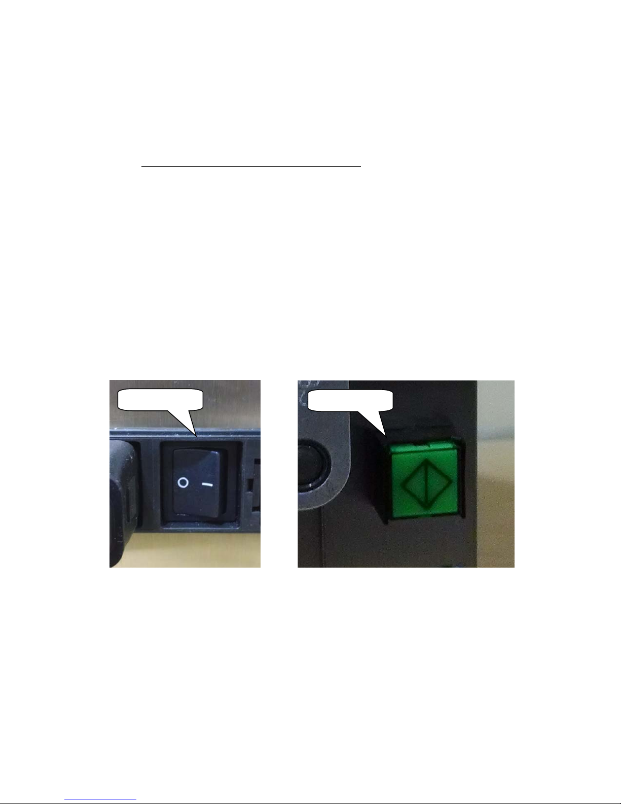
7. When the gauge is not in use, ensure that the power is turned off.
2GAUGEPOWER
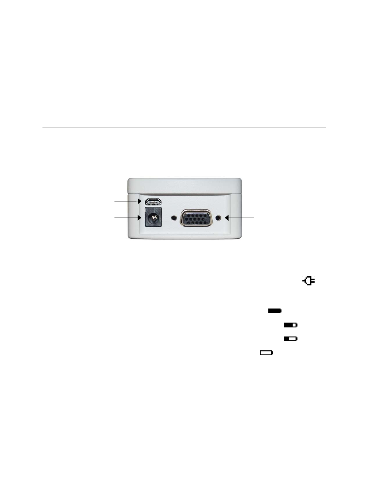
The gauge is powered either by an 8.4V NiMH rechargeable battery or by an AC adapter. Since the
batteries are subject to self discharge, it may be necessary to recharge the unit after a prolonged period
of storage. Plug the accompanying charger into the AC outlet and insert the charger plug into the
receptacle on the gauge (refer to the illustration below). The battery will fully charge in approximately 8
hours.
Caution!
Do not use chargers or batteries other than supplied or instrument damage may occur.
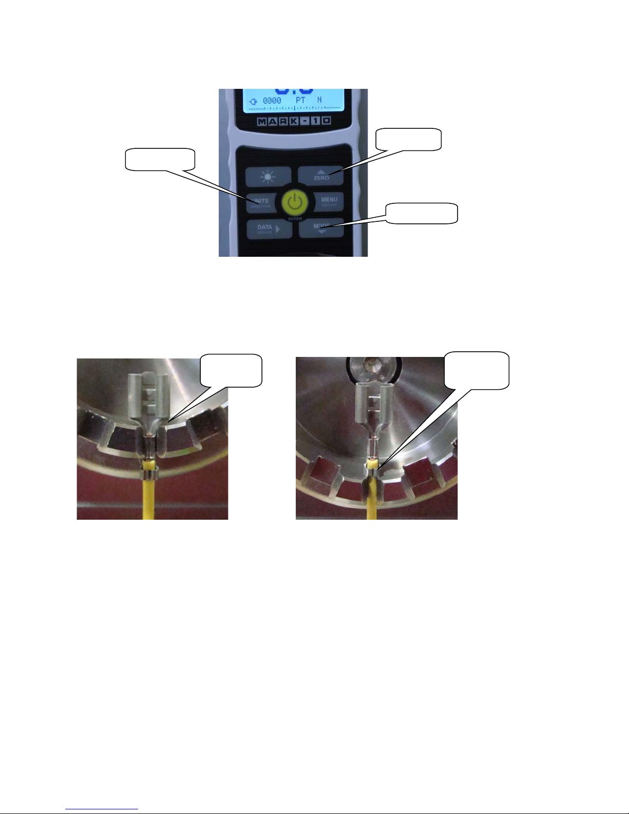
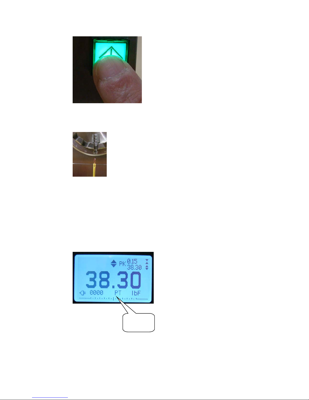
If the AC adapter is plugged in, an icon appears in the lower left corner of the display, as follows:
If the AC adapter is not plugged in, battery power drainage is denoted in a five-step process:
1. When battery life is greater than 75%, the following indicator is present:
2. When battery life is between 50% and 75%, the following indicator is present:
3. When battery life is between 25% and 50%, the following indicator is present:
4. When battery life is less than 25%, the following indicator is present:
5. When battery life drops to approximately 2%, the indicator from step 4 will be flashing.
Several minutes after (timing depends on usage and whether the backlight is turned on or
off), a message appears, “BATTERY VOLTAGE TOO LOW. POWERING OFF”. An audio
tone will sound and the gauge will power off.
The gauge can be configured to automatically power off following a period of inactivity. Refer to the Other
Settings section for details.
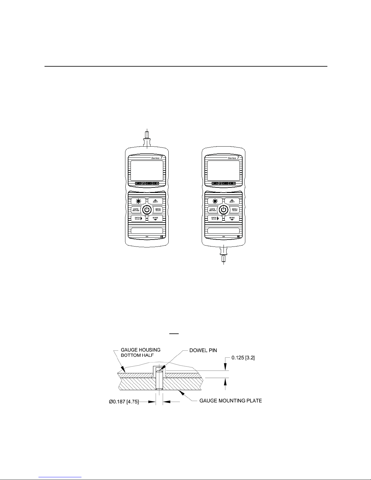
If battery replacement is necessary, it can be accessed by separating the two halves of the gauge. Refer
to the Setup section for details.
Serial connector
USB connector
Power input jack

9
3GUAGESETUP
3.1 Mechanical Setup
3.1.1 Loading shaft orientation
In order to accommodate a variety of testing requirements, the orientation of the loading shaft may be set
up in either of the two positions shown below. In order to change the loading shaft orientation, loosen two
captive screws on the back side of the housing, separate the two housing halves, rotate one half 180
degrees, and reassemble. Contact between the two halves is made by spring pins and contact pads on
the printed circuit boards.
Load cell shaft up Load cell shaft down
3.1.2 Mounting to a plate
Proper mounting is important if attached to a fixture or test stand. The round steel insert with a hole in the
back of the housing is provided to withstand the load during a test. A mating dowel pin should be used
(see illustration below). Mounting plates on Mark-10 test stands include a dowel pin and clearance holes
for the four threaded holes located near the corners of the housing. These holes are designed to
accommodate screws in order to hold the gauge in place (Mark-10 test stands include a set of thumb
screws for gauge mounting). The screws must not be used for load bearing purposes. Failure to use a
dowel pin properly can result in a hazardous situation.
3.1.3 Mounting attachments to the gauge
The force gauge’s threaded loading shaft is designed to accommodate common grips and attachments
with female mounting holes. To mount a grip, gently thread it onto the shaft. Other mounting adapters are

10
also available to prevent rotation. Ensure that the grip or fixture is positioned to ensure axial load with
respect to the loading shaft of the force gauge. When using a grip, ensure that it secures the sample in
such a way that it is prevented from slipping out during a test, preventing a potential safety risk to the
operator and others in the vicinity. If using a grip or fixture from a supplier other than Mark-10, ensure that
it is constructed of suitably rugged materials and components.
Do not use jam nuts or tools to tighten grips or attachments onto the shaft. Finger-tighten only.
3.2 Installing the USB driver
If communicating via USB, install the USB driver provided on the Resource CD. Installation instructions
may also be found on the CD or may be downloaded from www.mark-10.com.
Caution!
Install the USB driver before physically connecting the gauge to a PC with the USB cable.
Further instructions for configuring and using the gauge’s outputs are provided in the Communications
and Outputs section.
4HOMESCREENANDCONTROLS
4.1 Home Screen
No. Name Description
1 Tension /
compression
indicator
- indicates a compression (push) direction
- indicates a tension (pull) direction
These indicators are used throughout the display and menu.
2 Compression The measured compression peak reading. This reading may be reset by
1
2
4
5
678
10
11
12
13 3
9

11
Peak pressing ZERO or by powering the gauge off and on.
3 Tension Peak /
Static COF
The measured tension peak. If the COF unit is selected, this represents the
static coefficient of friction. May be reset by pressing ZERO or by powering
the gauge off and on.
4 Primary reading
/ Kinetic COF
The current displayed force reading. When the COF unit is selected, this
reading represents the kinetic coefficient of friction upon completion of an
Averaging sequence. See Operating Modes section for details.
5 Load bar
Analog indicator to help identify when an overload condition is imminent. The
bar increases either to the right or to the left from the midpoint of the graph.
Increasing to the right indicates compression load, increasing to the left
indicates tension load. If set points are enabled, triangular markers are
displayed for visual convenience. This indicator reflects the actual load, which
may not correspond to the primary reading (depends on operating mode).
The ZERO key does not reset the load bar. See Operating Modes section for
details.
6 Units
The current unit of measurement. Abbreviations are as follows:
lbF – Pound-force
ozF – Ounce-force
kgF – Kilogram-force
gF – Gram-force
N – Newton
kN – Kilonewton
mN – Millinewton
COF – Coefficient of friction
XXXXX – User-defined unit (up to 5 characters)
Note: not all gauge capacities measure in all the above units. Refer to the
capacity / resolution table in the Specifications section for details. COF and
user-defined units must be enabled before they can be selected.
7 Break Detection
On/Off The letter “B” appears if the Break Detection function is enabled. Refer to the
Break Detection section for details.
8 Mode
The current measurement mode. Abbreviations are as follows:
RT – Real Time
PC – Peak Compression
PT – Peak Tension (corresponds to static COF)
A – Average (corresponds to kinetic COF)
ET – External Trigger
CAPT – Data Capture
2PK – 1st/2nd Peak
See Operating Modes section for details.
9 Number of
stored data
points
The number of stored data points in memory, up to 5,000. Displayed only if
Memory Storage or Data Capture functions are used.
10 Battery / AC
adapter
indicator
Either the AC adapter icon or battery power icon will be shown, depending on
power conditions. Refer to the Power section for details.
11 Automatic data
output indicator
If Auto Output has been enabled under Serial / USB Settings, this indicator
is displayed. When automatic data output is occurring, the icon becomes
animated. See Communications and Outputs section for details.
12 High / low limit
indicators
Correspond to the programmed set points. Indicator definitions are as follows:
– the displayed value is greater than the upper force limit
– the displayed value is between the limits
– the displayed value is less than the lower force limit
13 Set points The programmed force limits. Typically used for pass/fail type testing. 1, 2, or
no indicators may be present, depending on the configuration shown in the
Set Points menu item.

12
4.2 Controls
43
Primary Function
Secondary
Label Secondary Function
Powers the gauge on and off. Press
briefly to power on, press and hold
to power off. Active only when the
home screen is displayed.
ENTER Various uses, as described in the
following sections.
ZERO Zeroes the primary reading and
peaks.
(UP) Navigates up through the menu and
sub-menus.
MENU Enters the main menu. ESCAPE Reverts one step backwards through
the menu hierarchy.
MODE Toggles between measurement
modes.
(DOWN) Navigates down through the menu
and sub-menus.
DATA Stores a value to memory, transmits
the current reading to an external
device, and/or initiates automatic
data output, depending on setup.
DELETE
Enables and disables Delete mode
while viewing stored data / shifts
cursor to the right for certain
functions.
UNITS Toggles between measurement
units. DIRECTION Reverses the display during
calibration, and toggles between
tension and compression directions
while configuring set points and other
menu items.
Turns the LCD backlight on and off. N/A N/A
4.3 Menu navigation basics
Most of the gauge’s various functions and parameters are configured through the main menu. To access
the menu press MENU. Use the and keys to scroll through the items. The current selection is
denoted with clear text over a dark background. Press ENTER to select a menu item, then use and
again to scroll through the sub-menus. Press ENTER again to select the sub-menu item.
For parameters that may be either selected or deselected, press ENTER to toggle between selecting and
deselecting. An asterisk (*) to the left of the parameter label is used to indicate when the parameter has
been selected.
For parameters requiring the input of a numerical value, use the and keys to increment or
decrement the value. Press and hold either key to auto-increment at a gradually increasing rate. When
the desired value has been reached, press ENTER to save the change and revert back to the sub-menu
item, or press ESCAPE to revert back to the sub-menu item without saving. Press ESCAPE to revert one
step back in the menu hierarchy until back into normal operating mode.
Refer to the following sections for details about setting up particular functions and parameters.
5DIGITALFILTERS
Digital filters are provided to help smooth out the readings in situations where there is mechanical
interference in the work area or test sample. These filters utilize the moving average technique in which
consecutive readings are pushed through a buffer and the displayed reading is the average of the buffer
contents. By varying the length of the buffer, a variable smoothing effect can be achieved. The selection
of 1 will disable the filter since the average of a single value is the value itself.

13
To access digital filter settings, select Filters from the menu. The display appears as follows:
Two filters are available:
Current Reading – Applies to the peak capture rate of the instrument.
Displayed Reading – Applies to the primary reading on the display.
Available settings: 1,2,4,8,16,32,64,128,256,512,1024,2048,4096,8192. It is recommended to keep the
current reading filter at its lowest value for best performance, and the displayed reading filter at its highest
value for best visual stability.
6SETPOINTS
6.1 General Information
Set points are useful for tolerance checking (pass/fail), triggering an external device such as a motorized
test stand, or alarm indication in process control applications. Two limits, high and low, are specified and
stored in the non-volatile memory of the instrument and the primary reading is compared to these limits.
The results of the comparisons are indicated through the three outputs provided on the 15-pin connector,
thus providing “under”, “in range”, and “over” signaling. These outputs can be connected to indicators,
buzzers, or relays as required for the application.
6.2 Configuration
To configure set points, select Set Points from the menu. The screen appears as follows:
One, two, or none of the set points may be enabled. To toggle between the tension and compression
directions, press the DIRECTION key.
If two set points have been enabled, they are displayed in the upper left corner of the display. If only one
set point has been enabled, the word “OFF” appears in place of the value. If no set points have been
enabled, the upper left corner of the display will be blank.
When set points are enabled, the following indicators are shown to the left of the primary reading:
SET POINTS
Upper Disabled
* Upper Enabled
5.000 lbF
Lower Disabled
* Lower Enabled
3.500 lbF
DIGITAL FILTERS
(1 = Fastest)
Current Reading
1
Displayed Reading
1

14
– the displayed value is greater than the upper
force limit (NO GO HIGH)
– the displayed value is between the limits (GO)
– the displayed value is less than the lower force
limit (NO GO LOW)
Note: Set point indicators and outputs reference the displayed reading, not necessarily the current live load.
6.2.1 Set Point Outputs Schematic Diagram
6.3 Using Set Points to Control a Mark-10 ESM301 Motorized Test Stand
When using set points to stop/cycle crosshead motion on an ESM301 stand, the upper set point must
always be a value in the tension direction, and the lower set point must always be a value in the
compression direction. Both set points must be set, even if the intended application is to stop/cycle at
only one of the set points. The opposite set point should be a value sufficiently large that it does not get
triggered during the course of the test.
For certain other Mark-10 test stands, the tension and compression directions are reversed.
7BREAKDETECTION
The break detection function identifies when a sample has broken, clicked, slipped, or otherwise reached
a peak force and then fell by a specified percentage drop. Upon detection of the break, the gauge can
perform several automatic functions, depending on the mode in which break detection is enabled, as
follows:
1. Transmit the peak reading (Auto Output).
2. Save the peak value to memory (Auto Storage).

15
3. Zero the primary and peak readings (Auto Zero).
4. Toggle a pin (for example, to stop crosshead movement on a Mark-10 motorized test stand).
Break detection functions and settings are configured from a central location, and apply to any mode in
which it is enabled. Refer to the Operating Modes section for details on configuring each mode.
7.1 Configuration
To enable Break Detection and configure the automatic functions, select Break Detection from the main
menu. The display appears as follows:
Select “+ More” for additional options:
Any combination of the above functions may be selected.
If tones are enabled, a tone will sound when the output, storage, and zero functions have occurred.
7.2 Break Settings
Select Break Settings from the Break Detection menu to configure the settings. The display appears as
follows:
Function Description
Enabled-End Test
Arms the break detection function. When enabled, the letter “B” will appear on
the home screen, between the Mode and Unit indicators. Refer to the Home
Screen and Controls section for details. Applies to modes in which a Break
Detect Stop Condition is specified.
Enabled-Abort Same as above, except applies to situations in which a premature break occurs
before the specified Stop Condition is reached.
Break Settings Refer to the following sub-sections for details.
Auto Output
Auto Storage Automatically stores the peak reading to memory.
Auto Zero Automatically zeroes the display following data transmission and/or storage.
BREAK DETECTION 2
* Auto Storage
* Auto Zero
Auto Zero Delay
3 sec.
BREAK DETECTION
* Disabled
Enabled-End Test
Enabled-Abort
+ Break Settings
+ Auto Output
+ More

16
7.3 Auto Output Settings
Scroll to Auto Settings in the Break Detection menu and press ENTER to configure the auto output
settings. Any combination may be selected. The display appears as follows:
Parameter Description
RS232/USB Output Automatically output the peak when the break (% Drop) is detected.
Mitutoyo Output Automatically output the peak when the break (% Drop) is detected.
Output Pin
Automatically toggle the SP1, SP2, or SP3 pins (active low). If not required, select
“NONE”. To stop a Mark-10 ESM301 test stand when a break occurs, specify
SP2 if the break is in the tension (upwards) direction, or SP1 for the compression
(downwards) direction.
Note: Because the same pins are also used for set points, the stand will stop at
whichever condition occurs first.
8OPERATINGMODES
Caution!
In any operating mode, if the capacity of the instrument has been exceeded by more than 110%,
the display will show “OVER” to indicate an overload. A continuous audible tone will be sounded
until the MENU key has been pressed or the load has been reduced to a safe level.
Threshold Sets the percentage of full scale at which the break detection function becomes
active. This threshold is provided to ignore peaks that can occur during sample
loading and unloading.
Available settings: 5–90%, in 5% increments.
% Drop Sets the percentage drop from the peak reading at which the break is detected.
Available settings: 5%–90% in 5% increments.
Auto Zero
Delay Sets the time delay before the primary and peak readings are zeroed. Auto zero
can be disabled if required. Refer to the Auto Output Settings sub-section for
details. Available settings: 1–10 sec. in 1 sec. increments, and 10–60 sec. in 5 sec.
increments.
BREAK DETECTION
SETTINGS
Threshold: 5 %
% Drop: 50 %
AUTO OUTPUT
SETTINGS
RS232/USB Output
Mitutoyo Output
Output Pin: NONE

17
Several operating modes are possible with Series 7 gauges, as follows:
- Real Time (RT)
- Peak Compression (PC)
- Peak Tension / Static Coefficient of Friction (PT)
- Average Mode / Kinetic Coefficient of Friction (AVG)
- External Trigger (ET)
- Data Capture (CAPT)
- 1st/2nd Peak (2PK)
To cycle between the modes, press MODE while in the home screen. Refer to the following sections for
details for each mode:
8.1 Real Time (RT)
The primary reading corresponds to the live measured reading.
8.2 Peak Compression (PC)
The primary reading corresponds to the peak compression reading observed. If the actual force
decreases from the peak value, the peak will still be retained in the primary reading area of the display.
Pressing ZERO will reset the value.
8.3 Peak Tension / Static Coefficient of Friction (PT)
This is the same as Peak Compression, but for tension readings. If the COF unit is selected, the reading
in this mode represents the static coefficient of friction.
Note: The static COF is always displayed as the peak tension value in the upper right corner of the
display.
8.4 Average Mode / Kinetic Coefficient of Friction (AVG)
Average mode is used to obtain an average
force reading over a specified period of time.
This reading also represents the kinetic
coefficient of friction, if the COF unit is selected.
Applications include measurement of peel force,
COF, muscle strength, frictional force, and other
tests requiring time-averaged readings.
Before the parameters of Average Mode can be
configured, it must be enabled. To do so, select
Average Mode from the menu, scroll to
Enabled and press ENTER. The display
appears as follows:
Then, scroll to Settings and press ENTER to configure the parameters. The parameters are as follows:
AVERAGE MODE
Disabled
* Enabled
+ Settings
+ Auto Settings
Out
p
ut Pin: NONE

18
Parameter Description
Initial Delay The time delay, in seconds, before the averaging sequence commences.
Averaging Time The time duration, in seconds, of the averaging sequence.
Trigger Force
The minimum force required to start the averaging sequence. Toggle between
compression and tension directions by pressing the DIRECTION key. Initial delay
follows the trigger force.
Upon completion of an averaging sequence, several functions can occur, as configured in the
Auto Settings section:
Parameter Description
RS232/USB
Output Automatically output the average via RS-232 or USB at the completion of the
averaging sequence.
Mitutoyo Output Automatically output the average via Mitutoyo (Digimatic) at the completion of the
averaging sequence.
Memory Storage Automatically store the average at the completion of the averaging sequence.
Auto Zero Automatically zero the reading at the completion of the averaging sequence. This
re-arms the gauge for a new averaging sequence as if ZERO has been pressed.
Auto Zero Delay
The amount of time before the auto-zero occurs, in seconds:
Available settings: 1-10 sec., in 1 sec. increments, and 10-60 sec., in 5 sec.
increments.
Output Pin Automatically toggle the SP1, SP2, or SP3 pins (active low). If not required, select
“NONE”. To stop a Mark-10 ESM301 test stand when averaging is completed,
specify SP2 if moving in the tension (upwards) direction, or SP1 for the
compression (downwards) direction.
Note: Because the same pins are also used for set points, the stand will stop at
whichever condition occurs first.
After the parameters have been configured and the menu has been exited, press MODE until AVG is
displayed. Then press ZERO. Average mode is now armed, and the averaging sequence will commence
when the trigger force has occurred. The current status of the averaging sequence is displayed below the
primary reading, as follows:
AUTO SETTINGS
* RS232/USB Output
* Mitutoyo Output
* Memory Storage
* Auto Zero
Auto Zero Delay
5 sec.
AVERAGE MODE
SETTINGS
Initial Delay
0.0
Averaging Time
5.5
Trigger Force

19
Step Status Description
1 TRIG WAIT The trigger force has not yet occurred.
2 INIT DLY The initial delay is currently taking place.
3 AVERAGING The gauge is collecting readings. The status will be flashing until averaging has
been completed.
4 AVRG DONE Averaging has been completed. The average force is displayed in the primary
reading.
At the completion of the averaging sequence, the peak values are retained until ZERO is pressed.
Another averaging sequence may be started after ZERO has been pressed (or auto-zeroed). To exit
Average mode, press MODE and select the desired measuring mode.
8.5 External Trigger (ET)
This mode of operation is useful for measuring electrical contact activation force as well as
synchronization of multiple instruments for a “snapshot” view of applied forces. It is possible to capture
the reading with a normally open contact (high to low transition of the trigger signal) or a normally closed
contact (low to high transition). A Mark-10 ESM301/ESM301L test stand may be automatically stopped
when an external trigger has occurred.
Before the parameters of External Trigger Mode can be configured, it must be enabled. To do so, access
the main menu, select External Trigger, scroll to one of the four available options and press ENTER.
The options are as follows:
Select “+ More” for additional options:
Option Description
Momentary High Low The display will freeze the captured reading until ZERO is pressed. Applies
to a high to low transition of the trigger signal.
Momentary Low High The display will freeze the captured reading until ZERO is pressed. Applies
to a low to high transition of the trigger signal.
Maintained High The display will show the captured reading only for as long as a high signal
is maintained.
Maintained Low The display will show the captured reading only for as long as a low signal
is maintained.
Auto Settings Functions exactly as described in Section 5.4. These parameter values are
EXTERNAL TRIGGER 2
+ Auto Settings
Output Pin: NONE
EXTERNAL TRIGGER
* Disabled
Momentary Hi->Lo
Momentary Lo->Hi
Maintained High
Maintained Low
+ More
Table of contents