取扱説明書
User’s Manual
AVNVM
3
Warning
Follow all product specification and warnings when using these products.
Our company does not guarantee every application, although we are constantly making every
effort to improve the quality and reliability of these products. The products used in equipment could
cause serious physical damage or property damage, if appropriate and safe design procedures are
not followed. We take no responsibility for these products if there was no written agreement
regarding the compatibility of the product with the application.
Please carry it out understanding instructions written in this book or a technical documentation if
you need assistance on product specification, installation/plumbing, operation and maintenance.
Cautions for design of piping and product selection
Warning
1. Please choose from the products within the specification range of the working conditions such as
medium, working temperature/pressure and so on.
2. Confirm the fluid compatibility with the wetted part of the products in the "Suitability List on Medium"
in the latest Dymatrix general catalogue (AV-V-029-EJ). (Parts may be damaged by a kind of a
medium.) Consult us on any medium, which is not listed in "Suitability List on Medium".Moreover, if
you intend to use it with compressed air or gas (such as air, nitrogen, ozone, or other gas), we do
not assume product liability of the Product.
3. If there are foreign substances in a fluid, please install a filter.
(It would make the valve unable to seal.)
4. Please contact us, when use for the fluid containing the crystalline substance.
(It would make the valve unable to seal.)
5. Use the products within the range of working pressure shown in this user's manual.
6. Use the products within the range of working temperature shown in this user's manual.
7. Use the products within the range of atmospheric temperature shown in this user's manual. Please
use the products upon confirmation of compatibility with material and atmosphere. Do not adhere
any fluid to the external surface of product.
8. Please refers to the latest instruction manual issued by each fitting maker, and attach the fitting as
instructed.
9. When preparing the bypath piping, avoid making the circuit a sealed loop, which would cause
breakage of the piping material.
10. Secure the maintenance space.
Cautions for installation and plumbing
Warning
1. Read in this user's manual (IOM-Manual) carefully prior to installation/plumbing.
2. Flush the piping completely and make sure that there is no foreign substances in the piping prior to
installation/plumbing of our product into it.
3. Confirm the leak inspection is carried out correctly after the installation/plumbing.
4. Make sure that the valves are free of tensile/compression/bending stresses.
5. Do not apply excessive load on valve.
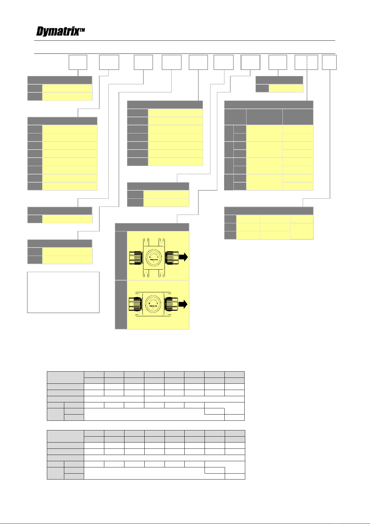
6. Confirm the flow direction of the valve matches the flow direction indication on the body.
7. Keep the valve away from excessive heat or fire. (It can be deformed or destroyed.)
8. Do not use the products in a place where they may become submerged in water.
Caution
1. Do not give any impact or drop the products.
2. Avoid scratching the products with any sharp object.