AsahiAV 14 User manual

Installation, Operation and Maintenance Manual
【H-V028-E-20】Diaphragm Valves Type 14 (True Union Diaphragm Valves Type14)
Serial No. H-V028-E-20
Contents
(1) Be sure to read the following warranty
clauses of our product 1
(2) General operating instructions 2
(3) General instructions for transportation,
unpacking and storage 2
(4) Name of parts 3
Nom. Size 15-50mm (1/2”-2”) 3
Nom. Size 15-50mm (1/2”-2”) with limit switch 4
Nom. Size 65-100mm(2 1/2”-4”) 5
Nom. Size 65-100mm(2 1/2”-4”) with limit switch 6
(5) Working pressure vs. temperature 7
(6) Specification of limit switch 8
(7) Installation procedure 8
Flanged end (PVC, C-PVC, PP, PVDF) 9
Threaded end (PVC, C-PVC, PP, PVDF) 10
Socket end (PVC, C-PVC) 11
Socket end & Spigot end (PP, PVDF) 12
(8) Connection of limit switch procedure 13
(9) Operating procedure 14
(10) Operating procedure of locking device 15
(11)Adjustment procedure for stopper 16
Nom. Size 15-50mm (1/2”-2”) 17
Nom. Size 65-100mm(2 1/2”-4”) 18
(12) Diaphragm replacement procedure 19
(13) Mounting an inserted metal and a base (panel) 20
(14) Inspection items 21
(15)Troubleshooting 21
(16) Handling of residual and waste materials 21
User’s Manual
Diaphragm Valves Type 14
True Union Diaphragm Valves Type 14

Installation, Operation and Maintenance Manual
【H-V028-E-20】Diaphragm Valves Type 14 (True Union Diaphragm Valves Type14) 1
This user’s guide contains very important information for the proper installation, maintenance and safe use of an
ASAHI AV Product. Please store this manual in an easily accessible location.
<Warning & Caution Signs>
This symbol reminds the userto take cautiondue to the potential forserious injury or death.
This symbol reminds the user to take caution due to the potential for damage to the valve if used in such a
manner.
<Prohibited & MandatoryAction Signs>
Prohibited: When operating the valve, this symbol indicates an action that should notbe taken.
Mandatory action:When operating the valve, this symbolindicates mandatory actions that must be adhered to.
(1) Be sure to read the following warranty clauses of our product
-Always observe the specifications of and theprecautions and instructions on using ourproduct.
- We always strive to improve productquality and reliability, but cannot guarantee perfection.
Therefore, should you intend to use this product with any equipment or machinery that may pose the risk of serious or
even fatal injury, or property damage, ensure an appropriate safety design or take other measures with sufficient
consideration given to possible problems. We shall assume no responsibility for any inconvenience stemming from any
action on your part without our written consent in the form of specifications or other documented approval.
- The related technical documents, operation manuals, and other documentation prescribe precautions on selecting,
constructing, installing, operating, maintaining, and servicing our products. For details, consult with our nearest
distributor or agent.
- Our product warranty extends for one and a half years after the product is shipped from our factory or one year after the
product is installed, whichever comes first. Any product abnormality that occurs during the warranty period or which
is reported to us will be investigated immediately to identify its cause. Should our product be deemed defective, we
shall assume the responsibilityto repair or replace it free of charge.
-Any repair or replacement needed after the warranty period ends shall be charged to thecustomer.
- Thewarranty does not cover the following cases:
(1) Using our product under any condition notcovered by our defined scope of warranty.
(2) Failure to observe our defined precautions or instructions regarding the construction, installation, handling,
maintenance, or servicing of our product.
(3)Any inconvenience caused by any product other than ours.
(4) Remodeling or otherwise modifying ourproduct by anyone other than us.
(5) Using any part ofour product for anything other than the intended use of the product.
(6) Any abnormality that occurs due to a natural disaster, accident, or other incident not stemming from something
inside our product.
Caution
W
arning

Installation, Operation and Maintenance Manual
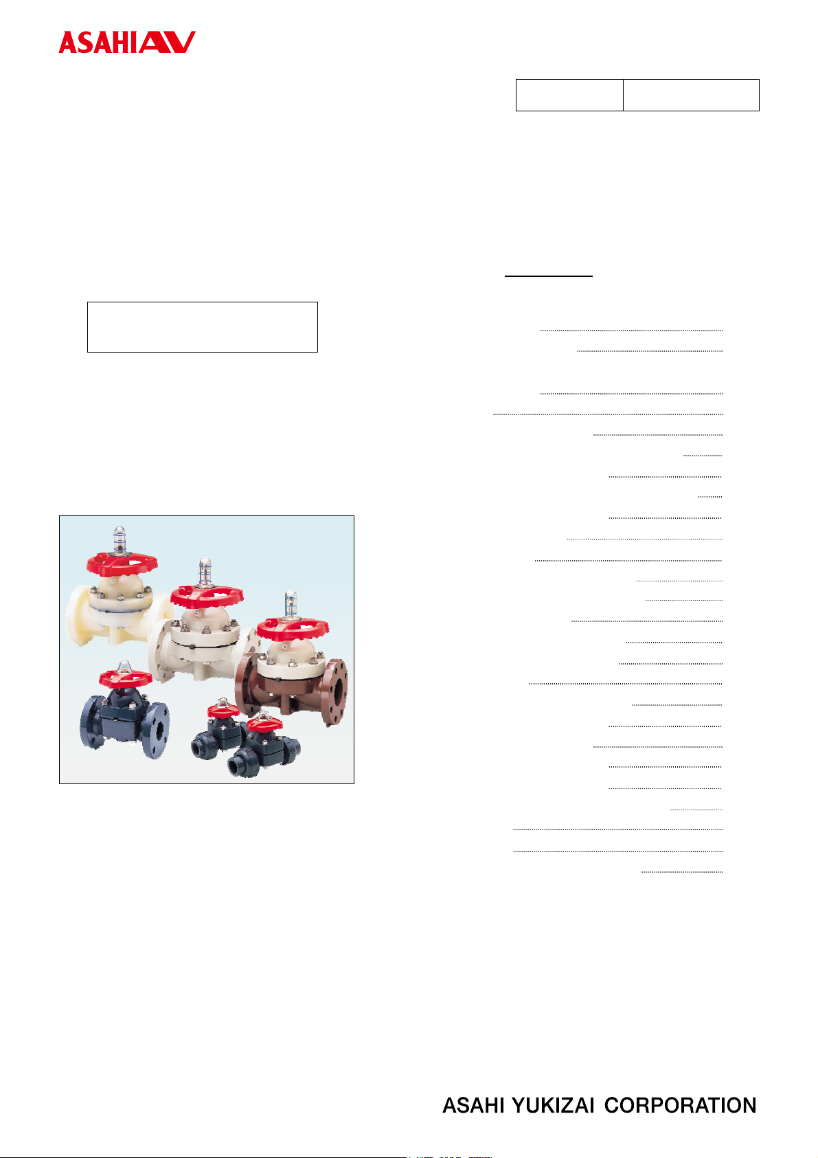
【H-V028-E-20】Diaphragm Valves Type 14 (True Union Diaphragm Valves Type14) 2
(2) General operating instructions
- Using a positive-pressure gas with our plastic piping may pose a dangerous condition due to the repellent force
particular to compressible fluids even when the gas is under similar pressures used for liquids. Therefore, be
sure to take the necessary safety precautions such as covering the piping with protective material. For
inquiries, please contact us. For conducting a leak test on newly installed piping, be sure to check for leaks
under water pressure. If absolutely necessary to use a gas in testing, please consult your nearest service
station beforehand.
- Do not step on or apply excessive weight on valve. (It can be damaged.)
- Do not use the valvein conditions where the fluid may have crystallized.
(The valve will not operate properly.)
- Keep the valve away from excessive heat orfire. (It can be damaged, or destroyed.)
-Always operate the valve within the pressure vs. temperature range.
(The valve can be damaged ordeformed by operating beyond the allowable range.)
-Allow sufficient space for maintenance and inspection.
- Select a valve material that is compatible with the media. For chemical resistance information, refer to
“CHEMICALRESISTANCE ONASAHIAV VALVE”.
(Some chemicals may damage incompatible valve materials.)
- Keep the valve out ofdirect sunlight, water and dust. Use cover to shield the valve.
(The valve will not operate properly.)
- Perform periodic maintenance. (Leakage may develop due to temperature changes or periods of prolonged
storage, rest, or operation.)
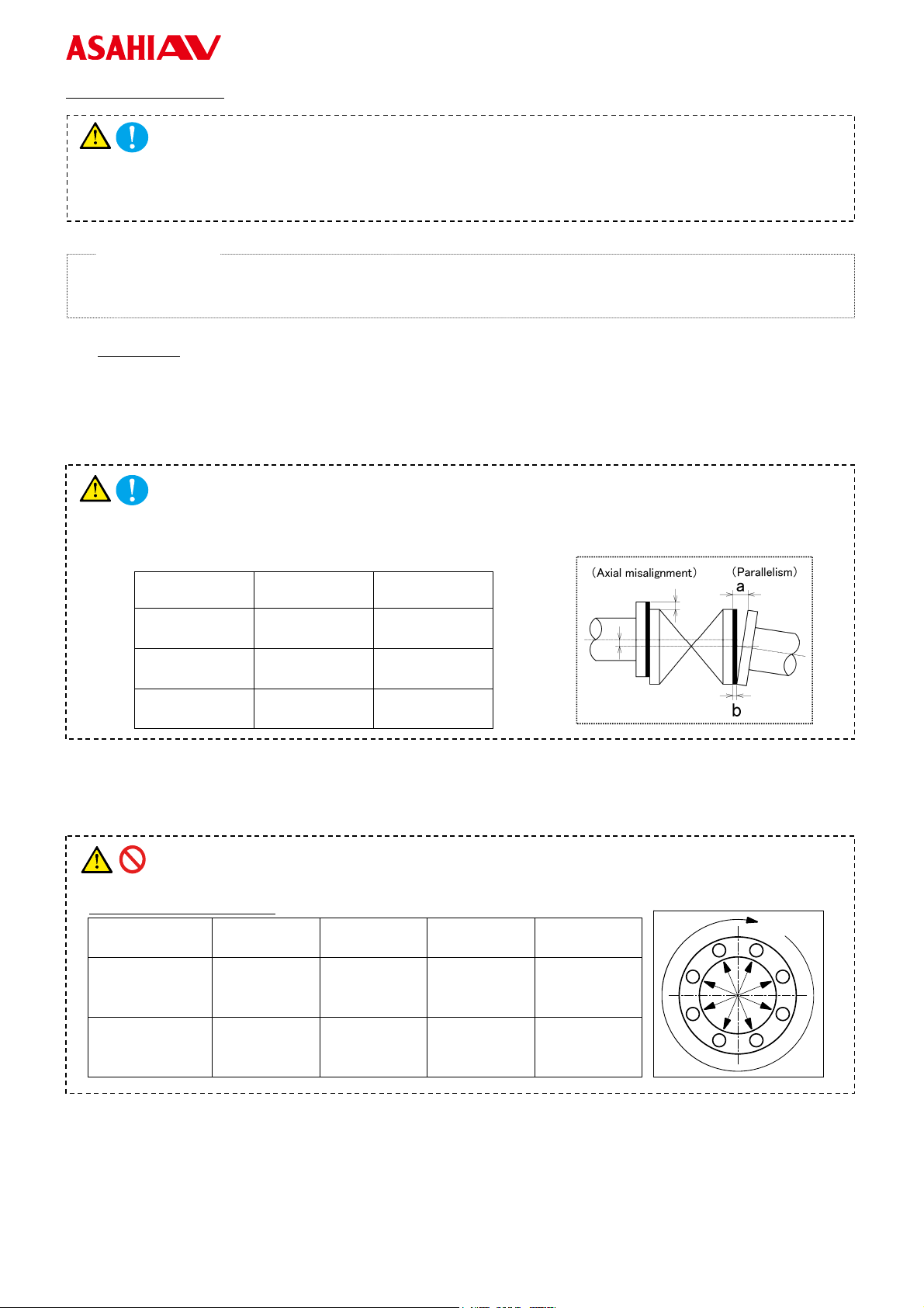
- Thetravel stop may have to be adjusted if media leakage is detected between the upstream & downstream
sides of the valve.
- Bonnet bolt torque should be checked before installation, as they may become loose after long-term storage.
-Aperiodic check ofthe valve condition as well as bonnet & flange bolt torque shouldbe made part of
preventative maintenance program properly re-tightening the bolts as necessary.
It is especially important to re-tighten all bolts during the first shutdown.
(3) General instructions for transportation, unpacking and storage
- When suspending and supporting a valve, takecare and do not stand under a suspended valve.
- This valve is not designed to handle impacts of any kind. Avoid throwing or dropping the valve.
-Avoid scratching the valve with any sharp object.
- Do not over-stack cardboard shipping boxes. Excessively stacked packages may collapse.
-Avoid contact with any coal tar creosote, insecticides, vermicides or paint.
(These chemicals may cause damage to the valve.)
- Store products in their corrugated cardboard boxes. Avoid exposing products to direct sunlight, and store
them indoors (at room temperature). Also avoid storing products in areas with excessive temperatures.
(Corrugated cardboard packages become weaker as they become wet with water or other liquid. Take care
in storage and handling.)
-After unpacking the products, check that they are defect-free and meet the specifications.
W
arning
Caution
W
arning
Caution

Installation, Operation and Maintenance Manual
【H-V028-E-20】Diaphragm Valves Type 14 (True Union Diaphragm Valves Type14) 3
(4) Name of parts
Nominal size: 15 - 50mm (1/2” - 2”)
* Cushion [4] is available only when diaphragm [3] is PTFE.
No. DESCRIPTION No. DESCRIPTION No. DESCRIPTION
[1] Body [11] Gauge Cover [22] Body Liner
[2] Bonnet [12] Name Plate [23] Liner
[2a] Bonnet(Handle lock) [13] Retaining Ring C-Type [24] Metal Insert (Ensat)
[3] Diaphragm [14] O-ring (A) [25b] End Connector (Socket End)
[3a] Inserted Metalof Diaphragm [15] O-ring (B) [25c] End Connector (Threaded End)
[4] Cushion [16] Thrust Ring (A) [25e] End Connector(Spigot End)
[5] Cushion Cover [17] Thrust Ring (B) [26] Union Nut
[6] Compressor [18] Bolt, Nut [27] O-ring (C)
[7] Joint [18a] Washer [186] Locking Lever
[8] Stem [19] Conical SpringWasher [187] Locking Plate
[9] Sleeve [20] Stopper(A) [188] Tapping Screw
[10] HandWheel [21] Screw
Rubber Diaphragm
PTFE Diaphragm
Option
PTFE Diaphragm
with Cushion Cover
Option
Option
Option
Option
Option
Option
Option
Option
Option

Installation, Operation and Maintenance Manual
【H-V028-E-20】Diaphragm Valves Type 14 (True Union Diaphragm Valves Type14) 4
Nominal side: 15 - 50mm (1/2” - 2”) with Limit Switch (Option)
No. DESCRIPTION No. DESCRIPTION
[62] Limit Switch [75] Nut (C)
[64] Limit Switch Pushing Plate [77] Thrust Ring (C)
[69] Bracket (A)

Installation, Operation and Maintenance Manual
【H-V028-E-20】Diaphragm Valves Type 14 (True Union Diaphragm Valves Type14) 5
Nominal size: 65 - 100mm (2 1/2- 4”)
* Cushion [4] is available only when diaphragm [3] is PTFE.
No. DESCRIPTION No. DESCRIPTION No. DESCRIPTION
[1] Body [11] Gauge Cover [20] Stopper
[2] Bonnet [12] NamePlate [22] BodyLiner
[3] Diaphragm [13] Retaining Ring C-Type [89] Compressor Pin
[3a] Inserted metal of Diaphragm [14] O-ring (A) [90] Stud Bolt・Nut
[4] Cushion [15] O-ring (B) [91] Upper Bonnet Liner
[5] Cushion Cover [16] Thrust Ring (A) [93] U-Bolt・Nut
[6] Compressor [17] Thrust Ring (B) [94] Metal of Compressor
[8] Stem [18] Bolt, Nut [98] Spring Washer
[9] Sleeve [18a] Washer (A) [99] Valve Sheet
[10] HandWheel [19] ConicalSpringWasher(A)
PTFE Diaphragm
with Cushion Cover
Option
P
T
F
E
D
i
a
p
h
r
a
g
m
Option
R
u
b
b
e
r
D
i
a
p
h
r
a
g
m
Option
Option
Option
Option

Installation, Operation and Maintenance Manual
【H-V028-E-20】Diaphragm Valves Type 14 (True Union Diaphragm Valves Type14) 6
Nominal size: 65 - 100mm (2 1/2” - 4”) with Limit Switch (Option)
No. DESCRIPTION No. DESCRIPTION
[62] Limit Switch [75] Nut (C)
[64] Limit Switch Pushing Plate [77] Thrust Ring (C)
[69] Bracket (A)

Installation, Operation and Maintenance Manual
【H-V028-E-20】Diaphragm Valves Type 14 (True Union Diaphragm Valves Type14) 7
(5) Working pressure vs. temperature

Installation, Operation and Maintenance Manual
【H-V028-E-20】Diaphragm Valves Type 14 (True Union Diaphragm Valves Type14) 8
(6) Specification of Limit Switch (Option)
Nominal Size Type Code Protection Grade
15 - 100mm
(1/2 - 4”) SL1-A IP67
Limit Switch Rating Connection Diagram
Rate Voltage (V) Resistive Load (A) Inductive Load (A)
AC125 5 3
AC250 5 3
DC8 5 3
DC14 5 3
DC30 5 3
DC115 0.5 0.1
DC230 0.25 0.05
(7) Installation procedure
- When suspending and supporting a valve, takecare and do not stand under a suspended valve.
- Be sure to conduct a safety check on all hand andpower tools to be used before beginningwork.
- Wear protective gloves and safety goggles as fluid remain in the valve even if the pipeline is empty. (You may
be injured.)
- When installing a pipe support by means of a U-band or something similar, take care not to over-tighten.
(Excessive force may damage the pipe.)
- When installing pipes and valves, ensure that they are not subjected to tension, compression, bending, impact,
or other excessive stress.
- When installing, disassembling, or reassembling the piping, fix the End Connector.
- Before a water test, be sure that the Union Nut is tightly fastened.
- Fasten the Union Nut while avoiding the parallelismand axial misalignment of the flange surface.
- When connecting anASAHIAV Valve to metal piping, take care not to let the pipe stress on theASAHIAV
Valve.
- Take care not to over-tighten the Union Nut. (The valve can be damaged.)
- Do not use the pipewrench. (The valve can be damaged.)
Conduit Hol
e
Rolle
r
W
arning
Caution

Installation, Operation and Maintenance Manual
【H-V028-E-20】Diaphragm Valves Type 14 (True Union Diaphragm Valves Type14)
9
Flanged end
(End connector materials: PVC, C-PVC, PP, PVDF)
- Use flat faced flanges for connection toAVValves.
- Ensure that the mating flanges are of the same standards.
- Be sure to use sealing gaskets (AV Gasket), bolts, nuts, and washers and tighten them to specified torques.
(When a non-AV gasket is used, a different tightening torque specification should be followed.)
●Torque wrench ●Spanner wrench
●AV gasket ●Bolt, Nut,Washer (For many flanges specification)
Procedure
1) Set theAV gasket between the flanges.
2) Insert washers and bolts from the pipe side, insert washers and nuts from the valve side, then temporarily tighten
them by hand.
- The parallelism and axial misalignment of the flange surface should be under the values shown in the following
table to prevent damage the valve.
(Afailure to observe them can cause destruction due to stress application to the pipe)
Unit:mm(inch)
Nom. Size Axial
misalignment Parallelism
(a-b)
15 - 32mm
(1/2” - 1 1/4”) 1.0 (0.04) 0.5 (0.02)
40, 50mm
(1 1/2”, 2”) 1.0 (0.04) 0.8 (0.03)
65 - 100mm
(2 1/2” - 4”) 1.0 (0.04) 1.0 (0.04)
3) Tighten the bolts and nuts gradually with a torque wrench to the specified torque level in a diagonalmanner.
(Refer to Fig.1.)
4) Tighten it more than 2 turns clockwise with specified torque. (Refer to Fig.1)
- Do not tighten at the specified torqueor more. (The valve can be damaged or leak.)
Recommended torque value Unit:N・m {kgf・cm}[lb・inch]
Nom. Size 15 - 20mm
(1/2” - 3/4”) 25 - 40mm
(1” - 1 1/2”) 50, 65mm
(2”, 2 1/2”) 80, 100mm
(3”, 4”)
PTFE・PVDF
coated
17.5
{179}
[155]
20.0
{204}
[177]
22.5
{230}
[200]
30.0
{306}
[266]
Rubber 8.0
{82}
[71]
20.0
{204}
[177]
22.5
{230}
[200]
30.0
{306}
[266]
Necessary items
Caution
Caution
Caution
Fig.1

Installation, Operation and Maintenance Manual
【H-V028-E-20】Diaphragm Valves Type 14 (True Union Diaphragm Valves Type14) 10
Threadedend
(End connector materials: PVC, C-PVC, PP, PVDF)
-Avoid excessive tightening. (The valve can be damaged.)
- Make sure that the threaded connections are plastic x plastic. (Metallic thread can cause damage.)
- Wrap the threaded joints on our plastic piping with sealing tape. (Anon-sealing tape can cause leakage.)
Using a liquid sealing agent or liquid gasket may cause stresscracks (Environmental Stress Cracking).
Our product warranty shall not apply in case of said use, evenwhen said use is unavoidable.
●Sealing tape ●Strap wrench ●Spanner wrench
Procedure
1) Wind a sealing tape around the external thread of joint, leaving the end
(about 3mm) free.
2) Loosen the unionnut [26] with a strap wrench.
3) Remove the union nut [26] and the end connector [25b].
4) Tighten the external thread of the joint and the end connector [25b]
hardly with hand.
5) Using a spanner wrench, screw in the end connector [25b]by turning 180°- 360°carefully without damaging it.
6) Make sure that the O-ring (C) [27]is mounted.
7) Set the end connector [25b]and union nut [26] directly on thebody without allowing the O-ring (C) [27]to come off.
8) Tighten union nut [26]on each valve until hand tight.
9) Using a strap wrench tighten unionnuts uniformly on each side approx 90°- 180°turns, 1/4 to 1/2 turns.
Necessary items
Sealing Tape
Caution

Installation, Operation and Maintenance Manual
【H-V028-E-20】Diaphragm Valves Type 14 (True Union Diaphragm Valves Type14) 11
Socketend
(End connector materials: PVC,C-PVC)
- When using an adhesive, ventilate the space sufficiently, prohibit the use of a fire in the vicinity, and do not
inhale adhesive vapors directly.
- If an adhesive gets into contact withyour skin, wash it off immediately.
If you feel sick or find any anomaly, receive a physician's diagnosis andtake appropriate measures promptly.
- Take care in doing work at low temperatures. Solvent vapors are hard to evaporate and are likely to remain.
(Solvent cracks may occur, damaging the equipment.) After assembling the piping system, open both ends
of the piping and use a fan (of the Low-Voltage Type) or something similar to ventilate the space, thus
removing the solvent vapors.
- Use the appropriateAsahiAV cement.
- Conduct a water test at least 24 hours after joining the pipes with an adhesive.
●AV cement ●Strap wrench.
Procedure
1) Loosen the union nut [26]with a strap wrench.
2) Remove theunion nut [26]and end connector [25b].
3) Lead the union nut through the pipe.
4) Clean the hubpart of the end connector [25b] by wiping with a waste cloth.
5) Apply adhesiveevenly to the hubpart of the end connector [25b] and thepipe spigot.
- Do not apply more adhesive than necessary. (The valve can be damaged due to solvent cracking.)
Adhesive quantity (guideline)
Nom. Size 15mm
(1/2”) 20mm
(3/4”) 25mm
(1”) 32mm
(1 1/4”) 40mm
(1 1/2”) 50mm
(2”) 65mm
(2 1/2”) 80mm
(3”) 100mm
(4”)
Quantity (g) 1.0 1.3 2.0 2.4 3.5 4.8 6.9 9.0 13.0
6) After applyingadhesive, insert the pipe quickly to the end connector [25b] and leave italone for at least 60 seconds.
- Do not under any circumstances try to insert a pipe into another fitting or valve by striking it, which may break
the piping.
7) Wipe away overflowing adhesive.
8) Make sure that O-ring (C) [27]is mounted
9) Tighten union nut [26]on each valve until hand tight.
10) Using a strap wrench tighten unionnuts uniformly on each side approx. 90°- 180°turns, 1/4 to 1/2 turns.
Necessary items
W
arning
Caution
Caution
Caution

Installation, Operation and Maintenance Manual
【H-V028-E-20】Diaphragm Valves Type 14 (True Union Diaphragm Valves Type14) 12
Socketend
&
Spigotend
(End connector materials: PP, PVDF)
●Strap wrench ●Welding machine
●User’s manual for welding machine
Procedure
1) Loosen the unionnut with a strap wrench.
2) Remove the union nut [26] and the end connector [25b].
3) Lead the union nut [26]through the pipe.
4) For the next step, refer to the user’s manual for the welding machine.
5) After welding,make sure that the O-ring (C) [27]is mounted.
6) Set the end connector [25b]and the union nut [26] directly without allowing the O-ring (C) [27] to come off.
7) Tighten union nut [26] on each valve until hand tight.
8) Using a strap wrench tighten union nuts uniformly on each side approx. 90°- 180°turns, 1/4 to 1/2 turns.
Necessary items

Installation, Operation and Maintenance Manual
【H-V028-E-20】Diaphragm Valves Type 14 (True Union Diaphragm Valves Type14) 13
(8) Connection of limit switch procedure
- Shut down the power on the equipment before connecting wires. There are risks of electrical shock
depending on the level of operating voltage.
- Connect the cables by using insulated sheathed crimping terminals in such a way as not to contact the cover or
housing. (Contact of a crimping terminal with the cover may disable the cover from being closed or may
cause a ground fault.)
- Be sure that the terminal cover and body cover are put onduring the operation.
●Phillips head screw driver ●Flathead screw driver ●Connector (G1/2)
●Wire stripper ●Terminal crimping tool
Procedure
1) Adjust a cable as shown in the figure below. (When installing a crimp style terminal on the lead wire, use crimp style
terminals with insulation sleeve (M3) so that, its doesnot contact the housing andother crimp style terminals.)
2) Remove the terminal coverfrom the housing by using a screw driver (-)
3) Draw a cable through each part as shown in the figure below.
4) Connect the crimp style terminal to theterminal board with a screw driver (+).
5)Attach the terminal cover to the housing.
6) Set the seal and washer, and tighten the nut to the terminal cover.
Necessary items
W
arning
Caution
Details of connection Details of cable
COM
NO NC
Cable
Grommet contact area
(Take care not to damage
the surface.)

Installation, Operation and Maintenance Manual
【H-V028-E-20】Diaphragm Valves Type 14 (True Union Diaphragm Valves Type14) 14
(9) Operating procedure
- Do not exert excessive force in closing the valve.
- Do not use the valveto fluid containing slurry. (The valve will not operate properly.)
- Theinstalled valve must never be opened or closed when foreign matter such as sand is present in the pipeline.
- When operating the handle, be sure to do so with your hand. (Using a tool may damage the handle.)
- Before opening or closing a lubricant free product,be sure to apply water.
- If a stopper is loose, adjust it. (To learn how to adjust it, see the operation manual.)
○Open and shut the valve by rotating handle wheel.
○The top of the travel stop will be flush with the top ofthe handle wheel when the valve is fully closed.
<Nominal size: 15-50mm (1/2”-2”) >
<Nominal size: 65-100mm (2 1/2”-4”) >
Full open Half open Full shut
Caution

Installation, Operation and Maintenance Manual
【H-V028-E-20】Diaphragm Valves Type 14 (True Union Diaphragm Valves Type14)
15
(10) Operating procedure of locking device
・Do not exert excessive force in turning the handle. (It can bedeformed, or destroyed.)
・Please lock using a padlock for misoperation prevention.
・The valve is simple locked at the time of shipment. Please operate valve after release simple lock.
・Do not disassemble the LOCKING DEVICE. (Injury may occur.)
1. Push the release lever with the locking holeto release the simple lock
2. Operate the valve to the desired valve lift.
3. Push the lock lever without the locking hole to lock the simple lock.
4. The location hole for the lock is already installed in the handle. Please lock using padlock as necessary. (Refer to Table
1 for the size of lock.)
Table 1 <Size of Lock>
Nominal Size mm (inch) Amm(inch)
15~32 (1/2-1
¼
") 5 (0.20")
40~50 (1
½
- 2") 6 (0.24")
Caution
Caution
Stateofunlock
Stateofsimplelock
Push to unlock
Push to lock
Locking hole
Release lever
Lock lever
A

Installation, Operation and Maintenance Manual
【H-V028-E-20】Diaphragm Valves Type 14 (True Union Diaphragm Valves Type14) 16
(11) Adjustment procedure for stopper
- If a stopper is loose, adjust it. (To learn how to adjust it, see the operation manual.)
- Tighten the stoppers securely. (Too weak a torque on a stopper may cause it to loosen.)
●Spanner wrench ●Allen wrench
●Screw driver(-) ●Protective Gloves ●Goggles
<Nominal size: 15-50mm (1/2”-2”) ><Nominal size: 65-100mm (2 1/2”-4”) >
Necessary items
Caution

Installation, Operation and Maintenance Manual
【H-V028-E-20】Diaphragm Valves Type 14 (True Union Diaphragm Valves Type14) 17
Travel stop adjustment
<Nominal size : 15-50mm (1/2”-2”) >
Tightening torque of the screw
Unit:N・m {kgf・cm} [lb・inch]
Nom. Size 15 - 32mm
(1/2” - 1 1/4”) 40, 50mm
(1 1/2”, 2”)
Torque value 8.0
{81}
[71]
12.0
{122}
[106]
①Turn valve handle clockwise to the full closed
position.
Remove the gauge cover, being careful not to
dama
g
e the
g
au
g
e cover
O
-
rin
g
.
②Remove the travel stop / position indicator with a
spanner wrench and loosen the axial set screw
counterclockwise with an Allen wrench. The
axial set screw is located within the brass travel
stop looking down.
③Loosen the travel sto
p
counte
r
-
clockwis
e
.
④Slowly tighten the hand wheel clock wise until the
leak-by stops.
⑤Tighten the travel stop clockwise until it stop and
the turn it back
(
counte
r
-
clockwise
)
180°.
⑥Secure the travel stop/position indicator with
wrench and tighten the axial set screw clockwise
with anAllen wrench.
⑦R
e
-
attach the
g
au
g
e cover.

Installation, Operation and Maintenance Manual
【H-V028-E-20】Diaphragm Valves Type 14 (True Union Diaphragm Valves Type14) 18
Travel stop adjustment
<Nominal size 65 - 100mm >
1) Loosen the gauge cover [11] with hand.
2) Loosen the upper nut [20]from the lower nut [20]with spanner wrench.
3) Loosen thelower nut [20].
4) Operate the handle wheel to tighten gradually until the leakage of fluid stops.
5) Tighten the lower nut [20]until it stop, and then turn itback (counter-clockwise) 180°.
6) Tighten the upper nut [20] to the lower nut [20] with spannerwrench.
7) Tighten the gauge cover [11].
Tightening torque of the screw
Unit:N・m {kgf・cm} [lb・inch]
Nom. Size 65 - 100mm
(2 1/2” - 4”)
Torque valve 15.0 {153} [133]

Installation, Operation and Maintenance Manual
【H-V028-E-20】Diaphragm Valves Type 14 (True Union Diaphragm Valves Type14) 19
(12) Diaphragm replacement procedure
- If you do work with the piping installed, drain the piping of all its fluid. Some fluid will remain in the valve.
Therefore wear protective goggles and protective gloves.
(You may otherwise get injured.)
●Torque wrench ●Spanner wrench
●Protective gloves ●Goggles
1) Drain fluid completely from the pipe line.
2) Remove valve bonnet from the body.
3) Turn handle of valve clockwise until it stops.(Do not force it).The
compressor should be fully extended out of the bonnet.
4) Bayonet connection type (standard)
Remove the diaphragm from the compressor by turning it 90°and
mount the new diaphragm by reversing step.
Make sure that the pin of inserted metal of diaphragm connects joint
completely.
* The standardis Bayonet type.
*After Diaphragm made of PTFE reverses installation difficulty and
Diaphragm, it installs it.
*Whether the pin of the burial metal fittings of Diaphragm made it
connect with Joint is confirmed.
Threaded connection type
Turn the diaphragm clockwise to remove the diaphragm and mount
the new diaphragmby reversing step.
5) Mount the bonnet to the valve by reversing step 2. Tighten bonnet bolts
by hand only.
6) Rotate the handle 360°counter-clockwise.
7) Using a torque wrench, tighten the bonnet bolts in a diagonal,
cross-cross pattern.
Bonnet torque value Unit : N・m{kgf・cm}[lb・inch]
Nom. Size
15, 20mm
(1/2”, 3/4”) 25, 32mm
(1”, 1 1/4”) 40mm
(1 1/2”) 50mm
(2”) 65mmm
(2 1/2”) 80mm
(3”) 100mm
(4”)
Rubber 3.0
{31}
[27]
5 .0
{51}
[44]
12.0
{122}
[106]
15.0
{153}
[133]
13.0
{133}
[115]
18.0
{184}
[160]
35.0
{357}
310
PTFE 5.0
{51}
[44]
8.0
{82}
[71]
15.0
{153}
[133]
20.0
{204}
[177]
15.0
{153}
[133]
20.0
{204}
[177]
40.0
{408}
[355]
8) Re-adjust the stopper if necessary.
Necessary items
Diaphragm
Caution
Bayonet connection
Inserted metal of diaphragm
Threaded connection
Inserted metal of diaphragm
Joint
Other manuals for 14
1
Table of contents
Other AsahiAV Control Unit manuals

AsahiAV
AsahiAV Type 55 User manual

AsahiAV
AsahiAV H-V074-E User manual

AsahiAV
AsahiAV H-A077-E-00 User manual

AsahiAV
AsahiAV 58 A User manual

AsahiAV
AsahiAV V82 User manual

AsahiAV
AsahiAV 58 S User manual

AsahiAV
AsahiAV AV Series User manual

AsahiAV
AsahiAV 15 User manual

AsahiAV
AsahiAV Type 55 User manual

AsahiAV
AsahiAV 14 User manual