Serial No.: H-A079-E-00
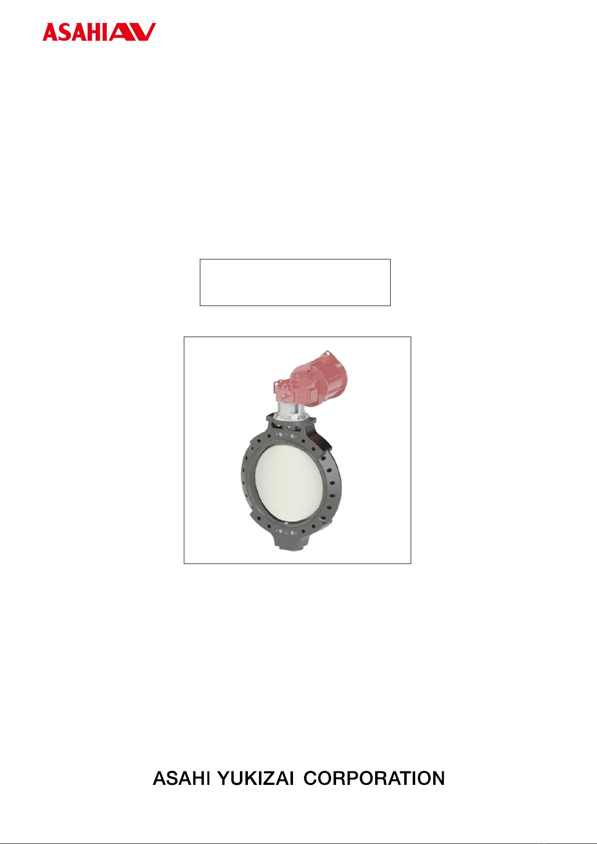
[User’s Manual] Butterfly valve Type 58 Pneumatic Actuated Type FL 700mm (28”) ~900mm (36”)
- 3 -
Table of contents
1. Our product warranty coverage···························································································4
Applicable to .......................................................................................................................................................................... 4
Warranty Period..................................................................................................................................................................... 4
Guaranteed range ................................................................................................................................................................. 4
Disclaimer............................................................................................................................................................................... 4
2. Safety Instructions················································································································5
Unpacking, Transportation and Storage .......................................................................................................................... 5
Product Handling .................................................................................................................................................................. 6
3. Name of each part·················································································································8
4. Product Specifications ·········································································································8
Product model code list ....................................................................................................................................................... 8
Relationship between maximum allowable pressure and temperature .................................................................... 9
Actuator................................................................................................................................................................................... 9
Standard option..................................................................................................................................................................... 9
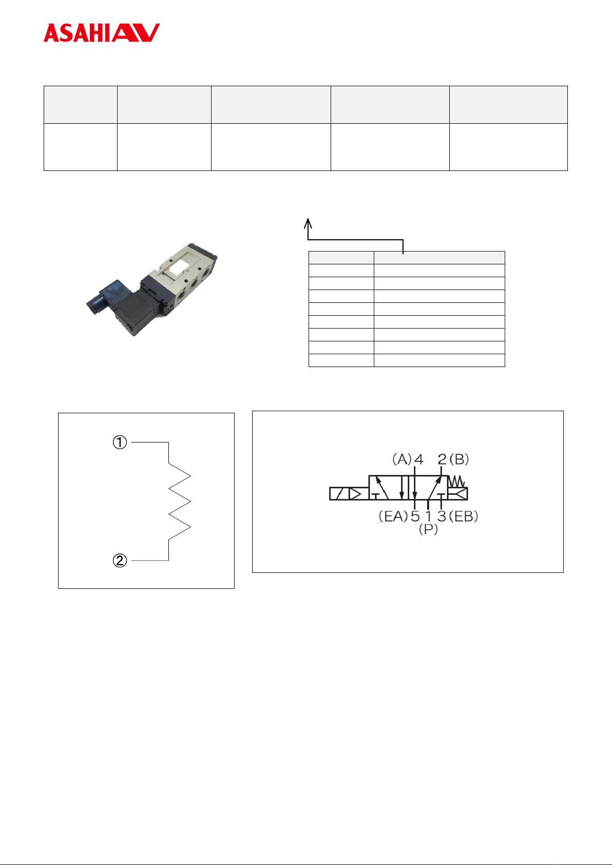
Solenoid Valve Specification ............................................................................................................................................ 10
Filter regulator specifications........................................................................................................................................... 11
Speed controller specifications........................................................................................................................................ 11
Limit switch box specifications........................................................................................................................................ 12
5. Piping method······················································································································13
Wafer shape ......................................................................................................................................................................... 13
Product support................................................................................................................................................................... 18
6. Air piping method················································································································19
7. How to Connect Options ····································································································21
Limit switch.......................................................................................................................................................................... 21
Solenoid valve...................................................................................................................................................................... 22
8. Manual operation ················································································································23
Manual operation................................................................................................................................................................ 23
9. Air Operation························································································································25
10. How to adjust the stopper································································································26
11. How to adjust open/close speed ····················································································27
12. Inspection item··················································································································28
Daily inspection................................................................................................................................................................... 28
Periodic inspection ............................................................................................................................................................. 29
13. Troubleshooting ················································································································31
14. How to inquire about defects or replacement·······························································34