Ascension VIRTUOSO 5460P Series Operating instructions
MAINTENANCE & REPAIR
MANUAL
Patented – see www.wheelchairlift.com/patents
ASCENSION VIRTUOSO
PORTABLE WHEELCHAIR LIFT
5460P MODEL SERIES
ASCENSION VIRTUOSO
PORTABLE WHEELCHAIR LIFT
5460P MODEL SERIES
MAINTENANCE & REPAIR
MANUAL

Copyright © 2014 Ascension, A Division of AGM, Tucson, Arizona
This document, or parts thereof, may not be reproduced in any form, by any method, for
any purpose, without written permission of Ascension.

TABLE OF CONTENTS
INTRODUCTION.............................................................................................................1
About This Manual.......................................................................................................1
Additional Information..................................................................................................2
Getting Help.................................................................................................................2
Contacting Ascension..................................................................................................2
SECTION 1: Terminology...............................................................................................3
SECTION 2: Routine Maintenance.................................................................................5
2.1 Hydraulic System..............................................................................................5
2.2 Cleaning............................................................................................................5
SECTION 3: Mechanical Disassembly and Repair.........................................................6
3.1 Important Preliminary Information.....................................................................6
3.2 Electrically Isolating the Lift...............................................................................6
3.3 Opening the Machinery Cabinets from the Top.................................................8
3.4 Retracting, Removing, and Reinstalling the Safety Skirt...................................9
3.5 Lower Landing Gate Closer ............................................................................15
3.6 Upper Lock Rollers .........................................................................................16
3.7 Lower Lock Rollers .........................................................................................18
3.8 Upper Stop Mechanism ..................................................................................20
3.9 Lower Landing Gate Switch............................................................................22
3.10 Upper Landing Gate Switch............................................................................24
3.11 Locking Rod Switch ........................................................................................25
3.12 Operating Stations..........................................................................................26
3.13 Override Keyswitch.........................................................................................27
3.14 Hydraulic Valves.............................................................................................28
3.15 Windows .........................................................................................................30
3.16 Skirt Guard......................................................................................................30
SECTION 4: Electrical Testing.....................................................................................36
4.1 Access to the Electrical Panel.........................................................................38
4.2 Testing the Switches.......................................................................................39
4.3 Testing the Relay Module ...............................................................................41

4.4 Testing the Power Supply...............................................................................42
4.5 Testing the Power Relay.................................................................................43
SECTION 5: Lift Compression/Expansion....................................................................44
5.1 Compressing the Lift.......................................................................................45
5.2 Expanding the Lift...........................................................................................49
5.3 Verification of Operation .................................................................................55
SECTION 6: Troubleshooting.......................................................................................56

Maintenance & Repair Manual Introduction
VIRTUOSO 5460P
110057 REV K
1
INTRODUCTION
The purpose of this manual is to provide the necessary information to perform
maintenance and repairs on the Ascension VIRTUOSO portable wheelchair lift. This
manual is intended to be used by skilled technicians who have experience working on
electro-mechanical systems and devices. Furthermore, these personnel should be well-
versed in standard industrial safety practices and procedures. The appropriate sections
should be read through completely before any repairs are begun.
About This Manual
This manual is divided into six sections:
Section 1 defines terms that are used throughout the remainder of this manual.
Section 2 describes the recommended procedures for performing routine maintenance.
Section 3 covers mechanical repair. This includes component replacement, as well as
detailed procedures to disassemble, test, and reassemble major components.
Section 4 covers electrical testing.
Section 5 describes how to compress the lift so that it can be rolled through a narrow
doorway and then expanded again for normal use.
Section 6 is a troubleshooting guide. It provides information for locating and correcting
any problems with the lift.

Maintenance & Repair Manual Introduction
VIRTUOSO 5460P
110057 REV K
2
Additional Information
The following sources of information supplement this manual:
Operating Manual An Operating Manual is supplied with each lift and includes all the
necessary information to set up, break down, store, and transport the lift. It also
includes the general safety precautions that should be observed.
Setup and Operation DVD A short setup and operation DVD is supplied with each lift.
Getting Help
If you have a question or problem with the lift, please try to find the solution in this
manual. In particular, be sure to review the troubleshooting guide in Section 6. If you
are not able to resolve the problem, please contact Ascension as indicated below,
making sure that you have the serial number of your lift ready. The serial number can
be found on the data plate located inside the lift car on the upper left rail. Also, it is
recommended that you contact Ascension while in the immediate vicinity of your lift, as
this will reduce the time required to properly diagnose the problem.
Contacting Ascension
Ascension's business hours are 8 a.m. to 5 p.m. Mountain Standard Time, Monday
through Friday.
Telephone: 800-459-0400 Mailing Address: Ascension
Fax: 520-881-4983 Customer Service
Email: sales@wheelchairlift.com PO Box 40020
Tucson, AZ 85717-0020

Maintenance & Repair Manual SECTION 1
VIRTUOSO 5460P
110057 REV K
3
SECTION 1: Terminology
To effectively use this manual, you need to be familiar with the following terms. Refer to
the figure on the following page for identification of components. Not all components
are shown in the figure.
Access Panel The hinged panels (four total) that provide access to the machinery
cabinets.
Back End The end of the lift where the upper landing gate is located.
Base The steel frame that rests on the floor when the casters are removed and
supports the operating mechanism.
Control Panel The electrical panel for the lift which contains the power supply, control
system relay, and the main power relay. The control panel is located inside the left-
hand machinery cabinet.
Dock Plate The hinged plate that bridges the gap between the lift car floor and the
upper landing surface when the lift car is at the upper landing.
Front End The end of the lift where the lower landing gate is located.
Lift Car The compartment in which the passenger rides.
Lower Landing Gate The gate that serves the lower landing (ground level).
Machinery Cabinet The enclosures in which the lifting and control mechanisms are
located. There is one cabinet on each side of the lift. The contents of the machinery
cabinets are accessible through the access panels.
Operating Stations The controls for raising and lowering the lift car. All three
operating stations are located on the left side of the lift car. The operating station inside
the lift car has an emergency stop switch.
Override Keyswitch The switch used to operate the lift while installing or removing the
casters.
Skirt The accordion-style cover which completely encloses the underside of the lift car.
The skirt consists of two parts: the lift car skirt, which surrounds the lift car on three
sides; and the gate skirt, which protects the area under the lower landing gate.
Upper Landing The stage, platform, or riser that the lift serves.
Upper Landing Gate The gate that serves the upper landing, or stage.
Maintenance & Repair Manual SECTION 1
VIRTUOSO 5460P
110057 REV K
4

Maintenance & Repair Manual SECTION 2
VIRTUOSO 5460P
110057 REV K
5
SECTION 2: Routine Maintenance
2.1 Hydraulic System
The fluid level of the hydraulic system should be checked every six months. Before
checking the fluid level, make sure the lift car is at ground level (i.e., at the lower
landing) and off its casters. Then open one of the access panels in the right-hand
machinery cabinet and verify that the fluid level in the reservoir sight tube is between
the min-max marks on the reservoir.
Inspect the condition of the hydraulic fluid. Change the fluid if it has darkened, appears
dirty, or has a strong acrid or burnt odor.
If you need to add hydraulic fluid to the lift, use an ISO 32 grade hydraulic oil, such as
Texaco Rando HD32 or 76 Unax AW32 filtered to 10 microns for lifts primarily used
indoors. For outdoor lifts use a low-temperature oil such as Amsoil AWF oil. In order to
add fluid to the reservoir, pull the top of the flexible sight tube out of the access panel
opening, remove the bronze vent plug, and pour the hydraulic fluid into the sight tube.
2.2 Cleaning
All parts of the lift except the windows may be cleaned with soap and water or general
purpose household cleaners. Use a sponge or soft cloth dampened with cleaning
solution. Wipe dry with a cloth after cleaning. Do not expose any part of the lift to a
direct liquid stream or spray, such as from a water hose.
To clean the windows, Windex or Formula 409 brand window cleaners may be used.
To remove scratches, Plastic Polish 2 or 3 is recommended. Plastic Polish is available
from Novus, Inc, Minneapolis, Minnesota, item numbers PC-20 and PC-30 respectively.

Maintenance & Repair Manual SECTION 3
VIRTUOSO 5460P
6110057 REV K
SECTION 3: Mechanical Disassembly and Repair
3.1 Important Preliminary Information
The repairs in this section are to be performed by a skilled technician who has
experience working on electro-mechanical systems. Furthermore, the technician should
be well-versed in standard industrial safety practices and procedures. In the United
States of America, electrical safety procedures are established in OSHA's
Lockout/Tagout – Hazardous Energy Sources Standard (29 CFR 1920.147).
Familiarity with the setup and operation of the lift is required to effectively perform the
repairs listed in this section. This information can be found in the Operating Manual
provided with the lift.
3.2 Electrically Isolating the Lift
This section describes the procedures for electrically isolating the lift, which is
necessary in order to safely perform some of the repairs covered in this manual.
To electrically isolate the lift, perform the following steps in the order listed:
1. Remove the electrical plug from the wall outlet.
2. Attach a DANGER tag to the end of the electrical plug and lock out the plug
according to the procedures established in OSHA's Lockout/Tagout – Hazardous
Energy Sources Standard (29 CFR 1920.147).
3. Coil the electrical cord and place it inside the lift car. This will prevent the cord from
inadvertently being plugged in while repairs are underway.
4. Turn the lift off. The ON/OFF switch is located on the control panel located inside
the left-hand machinery cabinet.
To restore power to the lift, perform the following steps in the order listed:
1. Remove the lock from the electrical plug.

Maintenance & Repair Manual SECTION 3
VIRTUOSO 5460P
7110057 REV K
2. Plug the power cord into a wall outlet with 120 VAC power.
3. Press "Reset" on the GFCI if necessary.
4. Turn the lift on.

Maintenance & Repair Manual SECTION 3
VIRTUOSO 5460P
8110057 REV K
3.3 Opening the Machinery Cabinets from the Top
For some of the repairs described in this manual, it is necessary to gain access to a
machinery cabinet from the top. The top of either machinery cabinet can be removed
by performing the following steps:
1. Remove the window located above the machinery cabinet from its frame. See
Section 3.15.
2. Use a Phillips screwdriver to remove the ten (10) flat head screws which hold the
cabinet top in place. The top can now be removed from the cabinet. It may be
necessary to open an access panel and push from inside the cabinet to pop the top
out.
To reinstall the machinery cabinet top, perform the above steps in reverse order.
Maintenance & Repair Manual SECTION 3
VIRTUOSO 5460P
9110057 REV K
3.4 Retracting, Removing, and Reinstalling the Safety Skirt
The safety skirt consists of two parts: the lift car skirt, which guards the lift car on three
sides; and the gate skirt, which guards the area under the lower landing gate. For some
of the repairs described in this manual, it is necessary to gain access to components
normally hidden behind the skirt. In most cases, only a small portion of the skirt may
need to be retracted; however, sometimes it may be necessary to remove the whole
skirt.
To remove the gate skirt, perform all of the following steps. If the skirt only needs to be
retracted, performing only Step 3 will provide access to many of the components behind
the skirt. Refer to the figure below for the location of the fasteners referenced in each
step.
1. Use a 5/16" wrench to remove the three (3) hex head screws that secure the skirt
to the skirt base. These screws are located on the top side of the skirt base.
2. Using any operating station, raise the lift car until the car floor is approximately
24" off the ground.

Maintenance & Repair Manual SECTION 3
VIRTUOSO 5460P
10 110057 REV K
3. Use a Phillips screwdriver to remove the three (3) screws that secure the skirt to
the lower landing gate.
4. Use a 5/32" hex key to remove the two (2) button head cap screws and washers
that secure the skirt guide tubes to the skirt base. Hold the skirt guide tubes
stationary with pliers if necessary while removing the screws.
5. Use a Phillips screwdriver to remove the four (4) screws (two (2) on each side)
that secure the skirt guide tube brackets to the lower landing gate and pull the
brackets downward, out of the gate. The skirt can now be removed from the
gate.
To reinstall the gate skirt, perform the above steps in reverse order.
To remove the lift car skirt, perform all of the following steps. If the skirt only needs to
be retracted, performing only Steps 2 & 3 will provide access to most of the components
behind the skirt.
1. If the whole skirt is to be removed, raise or lower the lift car so that the lift car floor is
approximately 15" off the ground.
2. Use a Phillips screwdriver to remove the 28 pan head screws that secure the sides
of the skirt to the lift car at the top and to the lift base at the bottom.
3. Use a 5/16" combination wrench to remove the four (4) hex head screws that secure
the top of the skirt to the lift car, one (1) at each corner. Remove the small skirt
support brackets that are freed when these screws are removed.
4. Use a Phillips screwdriver to remove the pan head screw that secures the back of
the skirt to the base.
5. In the back, retract the skirt around the ball-bearing slides as shown in the figure at
the top of the following page. You will need to hold each skirt panel approximately
horizontal to move it past the restraining tab.

Maintenance & Repair Manual SECTION 3
VIRTUOSO 5460P
11 110057 REV K
6. Push the ball bearing slide releases toward the right side of the lift and then pull
downward on the skirt guard to separate it from the lift car.
7. At the front of the skirt, use pliers or a similar tool to turn the skirt guide tubes
counterclockwise until they release from the studs in the base. You will need to lift
the corners of the skirt to gain access to the skirt guide tubes.
8. Retract the skirt guide tubes through the slots in the skirt. The skirt is now free of
the lift. Use extreme care to support the skirt in its natural position as much as

Maintenance & Repair Manual SECTION 3
VIRTUOSO 5460P
12 110057 REV K
possible while moving it. A minimum of two (2) people is recommended for moving
the skirt.
To reinstall the lift car skirt, perform the following steps in the order indicated. If
necessary, refer to the figures in the skirt removal instructions above for identification of
skirt components.
1. Raise or lower the lift car so that the lift car floor is approximately 15" off the ground.
2. Move the skirt into position around the lift car, approximately as it will be located
when installed on the lift. Use extreme care to support the skirt in its natural position
as much as possible while moving it. A minimum of two (2) people is recommended
for moving the skirt.
3. At both front corners of the lift car, lift the skirt guide tubes upward, move the skirt
into place, and insert the guide tubes through the slots in the skirt. Then turn the
guide tubes clockwise onto the base studs, using pliers to tighten them.
4. In the back, reinstall the skirt guard onto the lift car by performing the following
steps. Refer to the figure at the top of the following page as necessary.
a. Position the skirt guard underneath the ball-bearing slide rails on the lift car, so
that the slide rails on the skirt guard line up with the slide rails on the lift car.
b. Move the skirt guard upward, while making sure that the skirt guard tabs slide
behind the retaining flanges on the lift car, and that the slide rails on the skirt
guard lock into the slide rails on the lift car.
c. You will feel and hear a "click" when the ball-bearing slide rails engage each
other, and the skirt guard will be held in place. If the skirt guard was installed
correctly, the guard cannot be pulled away from the lift car. If this is not the case,
use the release levers to release the skirt guard and then reinstall it, taking care
to slide the skirt guard tabs behind the retaining flanges on the lift car.
CAUTION!
In the following step, stay clear of the lift car when it is moving to avoid any
pinching and/or crushing hazards.
Maintenance & Repair Manual SECTION 3
VIRTUOSO 5460P
13 110057 REV K
5. Lift the skirt upward on both sides of the skirt guard until the skirt slips past the
restraining tabs on the ball bearing slides as shown in the figure below. The
restraining tab must catch the skirt on the 5th panel down from the top of the skirt.

Maintenance & Repair Manual SECTION 3
VIRTUOSO 5460P
14 110057 REV K
6. Use a Phillips screwdriver to reinstall two (2) or three (3) pan head screws on each
side of the lift car to secure the top of the skirt loosely to the lift car.
7. Use a 5/16" combination wrench to reinstall the four (4) hex head screws that secure
the top of the skirt to the lift car, one (1) at each corner. Be sure to install the skirt
support brackets between the skirt and the lift car frame. See the figure below.
8. Use a Phillips screwdriver to reinstall the remainder of the 28 pan head screws that
secure the sides of the skirt to the lift car at the top and to the lift base at the bottom.
9. Use a Phillips screwdriver to reinstall the pan head screw that secures the back of
the skirt to the base.
Maintenance & Repair Manual SECTION 3
VIRTUOSO 5460P
15 110057 REV K
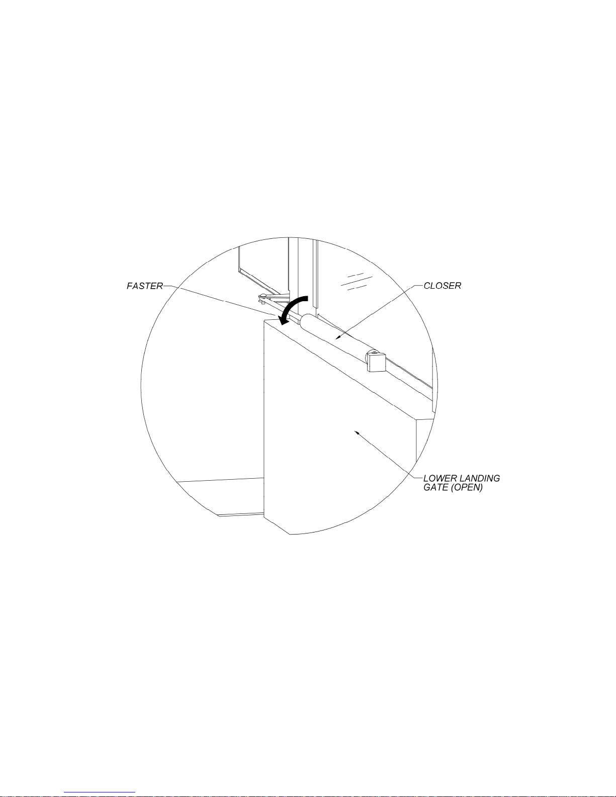
3.5 Lower Landing Gate Closer
To make the lower landing gate close faster, turn the gate closer
counterclockwise, 1/2 rotation at a time. To make the lower landing gate close
slower, turn the gate closer clockwise, 1/2 rotation at a time. See the figure
below.
Table of contents
Other Ascension Lifting System manuals


Popular Lifting System manuals by other brands

Haklift
Haklift SAKPBP Original instructions

Anchor
Anchor APEX 80 Use and maintenance

aidapt
aidapt VA147F Fitting and Maintenance Instructions

probst
probst FTZ-I Translation of original operating instructions

EAE
EAE EE-6435V2.B.PD Installation, operation, and parts manual

CMC
CMC S28 Use and maintenance manual

LSI-Robway
LSI-Robway RCI-1502 LM instruction manual

Harmar Mobility
Harmar Mobility HIGHLANDER EPL400 Installation and owner's manual

Terex
Terex Genie GS84D-401 Service and repair manual

TAWI
TAWI VM30 user guide

Sinoboom
Sinoboom TB20J Plus Operation manual

Skyjack
Skyjack Telescopic Boom Series operating manual


