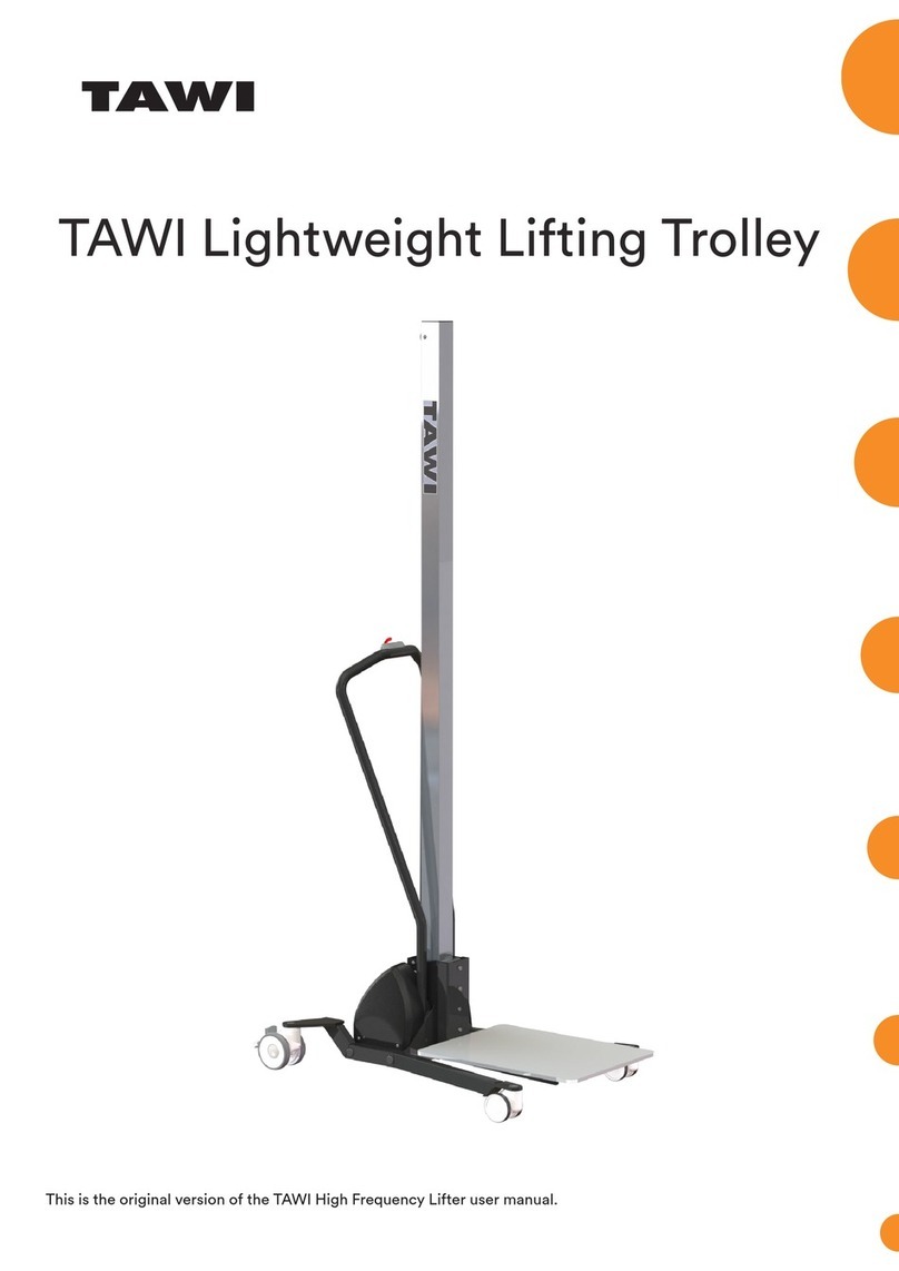
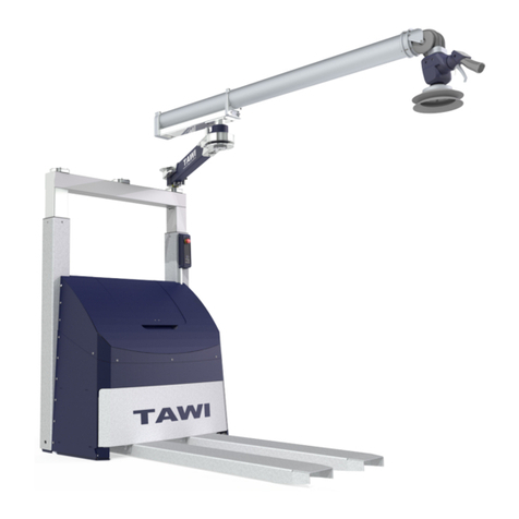
TAWI VM30 User manual

User guide for TAWI VacuEasylift

02
1 Overview
TAWI VacuEasylift is a line of lifters that lifts and lower loads using vacuum. TAWI VacuEasylift provide
lifting and transportation aid for loads up to 270 kg and can be equipped with dierent tools and
accessories.
The lifters are currently available in nine dierent models, mainly diering in lifting capacity and tube
area: VM0/40/50/60/80/100/120/180/270 This chapter presents an overview illustration of the lifters
and a table containing characteristics of the dierent models.
• The VM60 model is used for all illustrations in this manual. Your model may dier in appearance.
• Mounting the pump on a pump shelf or with a silencing hood is optional.
a
c
d
e
g
h
j
k
i
h
l
m
b
f
n
a. Vacuum pump
b. Silencing hood (optional)
c. Load balance adjustment screw (no load)
d. Load balance adjustment screw (with load)
e. Operating handle
f. Suction foot
g. Touch bolt
h. Suction head
i. Lift tube
j. Top swivel
k. Safety valve
l. Air hose
m. Filter unit
n. Main switch

03
Model VM30 VM40 VM50 VM60 VM80 VM100
Lifting
capacity
(kg)
30 40 50 60 80 100
Lift tube ø
(mm)
100 120 140 160 180 200
Stroke (mm) 1800/2600 1800/2600 1800/2600 1800/2600 1800/2600 1700/2400
Lift tube
length (mm)
2500/4000 2500/4000 2500/4000 2500/4000 2500/4000 2500/4000
Noise level,
Idle (dB)
73 76 76 76 76 78
Noise level,
In operation
(dB)
73 75 75 78 78 79
Model VM120 VM180 VM270
Lifting
capacity
(kg)
120 180 270
Lift tube ø
(mm)
230 250 300
Stroke (mm) 1700/2400 1500 1500
Lift tube
length (mm)
2500/4000 2500 2500
Noise level,
Idle (dB)
78 78 78
Noise level,
In operation
(dB)
79 79 79
Up and
down
motions
Variable speed - max 1 m/s (adjustable for light loads).
The max lifting capacity specied above are valid for standard congurations of the
lifters. Check the sticker on the lifter for applicable max load.
This table presents information about each model.

4
Install vacuum pump
1. Mount the vacuum pump in a suitable position
(a). Only use the eyebolt for lifting.
2 Installation
This chapter presents how to install the lifter and adjust the load balance before rst use. Plan the
dimensions of the crane system or jib crane so that you can work with the vacuum lifter over the whole
handling area. Remember that a jib crane is more eective if the lifting equipment is more often used at
the outer part of the jib arm.
c
A
A
a
b
3. Connect the vacuum pump power supply (c).
A motor circuit breaker with hold circuit relay
must be tted and set to the nominal current
shown on the motor serial plate (d; next page).
TAWI recommends using protection degree
IP54 for the breaker and cables. Installation may
only be carried out by an authorised electrician.
2. Make sure to install the pump so that it is pro-
vided with sucient air ow (A > 100 mm) (b).
A
A
b

5
g
PTC
M
3
u
I >I >I >
U1 V1 W1
M
3
M
3
RECOMMENDATION
OFF (O)
ON (I)
≥60s
21 MAX 10/h
L3L2L1
W1V1U1
L3L2L1
de
f
h
4. TAWI strongly recommends that the PTC is con-
nected to a thermal relay for overheating protec-
tion (e). Wait at least 60 seconds and let the fan
stop before turning it on again (f).
6. Verify function of the vacuum pump and that it
rotates in the clockwise direction (h). If the pump
rotates in the anti-clockwise direction, switch
electrical phases and test the pump again.
5. Remove the vacuum and pressure covers (g).

6
Install silencing hood
To reduce sound emissions from the pump,
a silencing hood can be mounted around the
vacuum pump (optional accessory).
1. Mount the provided outlet reducing socket
in the vacuum pump pressure outlet. Do not
use oil or put external load on sockets or
inlets or outlets.
2. Mount the vacuum pump on the base plate
with the four provided bolts (a).
3. Pull the electrical cable through the cable
entry and connect to the pump (see Install
vacuum pump on page 4) (b).
4. Connect the inlet hose from the baseplate to
the vacuum pump inlet reducing socket with
hose clamps (use a torque of min 5 Nm) (c).
5. Connect the outlet hose from the baseplate
to the vacuum pump outlet reducing socket
with hose clamps (use a torque of min 5 Nm)
(c).
6. Mount the silencing hood on the base plate.
Verify that the outlet is not blocked and that
there is enough space for air to ow freely
around the silencing hood (>100 mm, all
directions) (d).
7. Verify that the inlet and outlet hoses are cor-
rectly connected by referring to the sticker
on the silencing hood.
-
VACUUM
Oil
p
• Electrical installation may only be carried out by an authorised electrician.
• Do not switch or change the heat resistant pressure hose on the base plate. Use of another hose
than the one provided by TAWI may cause it to melt and cause permanent damage to the vacuum
pump.
• Do not mount any additional hoses on the silencing hood air outlet. This may cause the pump to
overheat.
• The silencing hood must not be modied in any way.
a
c
b
d

7
Install lter unit and air tubes
1. Mount the lter unit in the holder where it is
easy to reach and with the lter unit lid in the
upward direction (see gure).
2. An open lter unit control valve lowers lifting
speed and may be used by new operators.
Verify that the valve is closed before continu-
ing (a).
3. Connect section one of the air tube between
the vacuum pump and the lter unit with
hose clamps (use a clamp torque of 5 Nm)
(b).
4. Connect section two of the air tube between
the lter unit and the lift tube top swivel with
hose clamps (use a clamp torque of 5 Nm)
(c).
VM0/40/50 come with a reducing socket
which is placed inside the lter inlet. The l-
ter inlet and outlet are marked with an arrow.
a
c
b
open
close
• Take care to mount the lter unit in the correct orientation during reassembly. Damage to the
pump may occur if the lter unit is mounted upside-down.
• Make sure to install all air hoses as straight as possible. Sharp hose bends will reduce lifting ca-
pacity and may cause the pump to overheat.
• Do not use more than 30 m of hose for the entire installation. Lifting capacity will be reduced and
may cause the pump to overheat.

8
gfe
dcba
Shorten or change lift tube
If necessary, the lift tube may be shortened or changed. First mount the top swivel, then the suction
head.
Mount top swivel
1. For VM60-80: Identify which end of the tube is the lower, reinforced part. For VM100-270 the com-
plete tube is reinforced (a).
2. Start at the top of the tube. Cut o two complete spriral windings from the end (three windings for
models VM100-270) (b).
3. Pull out the spiral carefully. Take care not to damage the neoprene.
4. Bend the spriral end so that it cannot damage the material.
5. If necessary, cut the tube for a straight edge. Leave approximately 1,5-2 cm of neoprene (approxi-
mately 5,5 cm for models VM100-270) (c).
6. Push the top swivel into the lift tube (d). At least one complete spiral winding must cover the swivel.
7. Make sure the area is clean and dust free before taping. Attach the lift tube to the swivel with at
least three layers of duct tape under each clamp (e).
8. Attach the clamp right next to, but NOT on top of the rst spiral winding. Check that the clamp
position is straight before tightening (f).
9. Tighten the lift tube clamp. Refer to the table below for correct clamp torques for your model.
10. Attach the second clamp beside the rst one and tighten (VM60-80: one power clamp only).
11. Cover the clamp attachment with two pieces of duct tape (15 cm) (g).
12. Pull down the rubber band to cover the clamps and duct tape. Continue to mount the suction head.

9
e
dcba
2cm
Model VM30-50 VM60-80 VM100-270
No. of clamps Two clamps (top swivel)
One clamp (suction head)
One power clamp Two power clamps
Torque >6 Nm >18 Nm > 20 Nm
Mount suction head
1. On the suction head side: repeat steps 1-5 from Mount top swivel on page 8. Put the rubber
band around the lift tube, approximately 10 cm from the end (a).
2. Insert the suction head into the lift tube (b).
3. Allow the lift tube neoprene material to cover at least two cm measured from the top of the suction
head.
4. Make sure the area is clean and dust free before taping. Attach the lift tube to the suction head with
at least three layers of duct tape under each clamp (c).
5. Attach the clamp right next to, but NOT on top of the rst spiral winding. Check that the clamp
position is straight before tightening (two power clamps for models VM100-270) (d).
6. Tighten the lift tube clamp. Refer to the table below for correct clamp torques for your model.
7. Cover the clamp attachment with two pieces of duct tape (15 cm) (e).
8. Pull down the rubber band to cover the clamps and duct tape.
9. The lifter is now ready for a test lift.

10
• The dierent models are equipped with dierent types and number of clamps. It is extremely
important to identify which model you are working on (see machine sign). Only use the clamps
provided by TAWI.
• The lift tube clamps must NEVER cover anypart of the tube spiral winding.
• TAWI assumes no responsibility for unauthorized modications.
• Cutting the lift tube may change the characteristics of the VacuEasylift. TAWI must authorize all
modications of the lift tube.
• Use protective eye wear.
• These instructions must be carefully followed. Failure to do so may cause the unit to fall down
and cause bodily injuries.
Install suction foot and touch
bolt
1. Fit the suction foot or quick change attachment
with two or four M6 (VM30-120) or M8 bolts
(VM180/270) directly to the suction head. Use a
torque between 2-3 Nm for the bolts.

11
• The touch bolt can be removed if it is in the way for normal lifting operations. Remove the bolt
and plug the bolt hole with a standard M8 bolt and nut.
• The touch bolt must be adjusted to the exact right position depending on the suction foot. Please
contact your salesman to be sure of the position.
≈20mm
a
• Make sure to use the correct torque for the bolts when installing the suction foot. Do not over- or
undertighten. Air leakage may occur otherwise, reducing lifting capacity.
• If the quick release attachment is used, the touch bolt must be removed.
≈10mm
b
The touch bolt provides help for the operator by
opening the suction head valve fully, enabling a
good grip of the load.
2. Fit the touch bolt:
a. Fit the touch bolt with the head of the bolt
about 10-20 mm below the edge of the suc-
tion foot (a).
b. If the suction foot for sacks is used, adjust
the bolt head so that it is installed approxi-
mately 10 mm above the edge of the suction
foot (b).
3. If the quick change attachment is used, install
a suitable suction foot, see Change suction foot,
quick release on page 17.
4. Verify that the suction foot is securely fas-
tened to the suction head.

12
Install lifter in crane system
1. Suspend the lift tube from the top swivel in
the crane system or jib crane.
2. Adjust suspension so that there is at least 10
cm between the oor and the lowest part of
the suction foot.
3. Verify that the lift unit hangs and moves
freely so that unnecessary wear is avoided.
4. Verify that the crane system or jib crane is
horizontal so that the lift tube does not move
laterally by its own weight.
Adjust load balance
Balance the unit with and without load to a con-
venient level for the operator. This ensures that
the control handle is within comfortable reach at
all times.
1. Press the main switch to turn the power on.
2. Balance the unit WITH LOAD: Turn the red
knob carefully until the balance position is
reached.
3. Balance the unit WITHOUT LOAD: Loosen
the lock nut and turn the yellow knob care-
fully until the balance position is reached.
Tighten the lock nut.
• Adjust balance in the order provided by the instructions. If not, a readjustment of load balance
will be necessary.
• The adjustment screws are located in dierent positions depending on handle type (see illustra-
tions on next page).

13
Load adjustment knob positions (with and without load), standard handle
Load adjustment knob positions (with and without load), ex handle

14
• The TAWI VacuEasylift lifters are made for use under a roof protected from wind and rain.
• The lighting in the place of installation must be adequate, during installation and operation.
• The overhead crane system/jib crane must be approved for the rated maximum lifting capacity of
the vacuum lifter.
• During design and installation of the suspending system, it is vital to take into account relevant
standards and regulations, the load bearing capacity of the ceiling and oor structure and the
attachment devices and the relevant basic design information of the suspending system. For
information on suspension (jib crane, crane system etc) see separate manual.
• The overhead crane system must be installed by qualied technicians and all safety and main-
tenance instructions must be followed.
• Re-tighten all bolts within 1-2 months of installation.
• This vacuum lifter may not be used before the test in Appendix I has been carried out and signed.
• Do not start/test the vacuum pump before installation is complete and the suction foot is >10 cm
from ground!
• Any modications to the product must be carried out by qualied TAWI technicians.
• A mandatory dynamic operational test must be executed before the vacuum lifter may be put
into operation.
• Motion limiters may not be used to limit the horisontal motion of the vacuum lifter. The installa-
tion of a motion limiter may cause serious damage to the vacuum lifter. It may also cause involun-
tary disengagement of parts resulting in parts falling down and the risk of serious body injuries.
• Note the colour code system for safe assembly of lift unit to suction foot /accessory. ONLY
PARTS WITH MATCHING COLOUR CODE MARKING MAY BE ASSEMBLED! Incorrect combina-
tions of lift unit and accessory may cause very serious injuries.
Verify installation
When the installation of the vacuum lifter is carried out, and before the vacuum lifter is put into
operation, it must be submitted to a dynamic operational test at the place of installation. The dynamic
operational test must be carried out by qualied technicians with a load of 1.1 times the maximum load
specied by the manufacturer.
This test shall be carried out for each motion of the vacuum lifter, testing its full function, with repeated
starts and stops throughout the complete working range.
This test shall be considered successful if the vacuum lifter has been found to perform all its functions
and if the examination subsequent to the test reveals no damage to mechanisms or structural
components, and no connection has been loosened or been damaged.

15
3 User instructions
This chapter describes how to operate TAWI VacuEasylift.
• A damaged electrical cable could cause electrical shock.
• The operator must be trained on the product and all instructions in the manual must be followed.
• When in operation the operator must not place his head above the unit.
• When in operation the operator must not be under a hanging load.
• The lift tube must be used only in a vertical position.
• The max lifting capacity (SWL) must not be exceeded.
• Use vacuum power only to handle the load. Do not lift the load by hand force.
• A load must never be left hanging for an extended period of time. This can cause the vacuum
pump to overheat.
Start lifter
Review and perform relevant inspections: see 6 Service & maintenance on page 19.
1. Press the main switch or remote control to turn the power on.
2. Verify that the lift unit hangs and moves freely so that unnecessary wear is avoided.
3. Verify function of the lifter.
4. The lifter is now ready for use.

16
Use lifter
Review and perform relevant inspections. See
6 Service & maintenance on page 19. The lter
has a control valve to reduce the lifting speed
when handling light loads, see Install filter unit and
air tubes on page 7.
1. Move the lift tube so that it can be placed
directly over the load.
2. Lower the suction foot towards the load by
pressing the operating handle downwards.
3. Allow the suction foot to grip the load.
4. Lift the load by pulling the operating handle
upwards (a).
5. Move the load to required position and lower
it by pressing the operating handle down (b).
6. Release the suction foot from the load,
a. by pressing the operating handle right to
the bottom and braking the seal (c), or
b. If a release valve is used (option-
al accessory; compatible with
model VM0/40/50/180/270 and
VM60/80/100/20 with ex handles): by
pressing the operating handle right to
the bottom and pulling the release valve
handle at the same time (d).
• Only run the lifter when it is completely assembled.
• Maintenance instructions must be followed.
• Service record must be accessible for inspection.
• Use only original TAWI parts.
• The top swivel joint includes a safety valve. The valve automatically closes if the power fails and
the load sinks to the oor in a controlled manner. Let go of the handle and move away from the
lifter.
• Check the lifter for safe functionality prior to each use, for instructions, see 6 Service & mainte-
nance on page 19.
b
a
c
d

17
Change suction foot, quick
release
The lifter can be equipped with optional tools for
dierent load types. The quick change attachment
enables easy tool changes.
1. If not done, mount the quick change attachement
on the suction head and foot according to the
instructions for Install suction foot and touch bolt on
page 10.
2. With the suction foot resting on a rm surface and
the vacuum pump turned o, pull and hold the
spring-loaded pins.
3. Remove the suction foot.
4. Verify that the suction foot is correct for your
model and the colour code matches (see warning
below).
5. Connect the new suction foot to the suction head
by rmly pressing it in the quick change attach-
ment until the spring-loaded pins engage.
6. Verify that the suction foot is rmly connected to
the suction head and that it does not rotate.
7. Verify that the lift unit hangs and moves freely so
that unneccessary wear is avoided.
8. Verify function of the lifter.
Note the colour code system for safe assembly of lift unit to suction foot/accessory. Each colour
corresponds to a specic VacuEasylift model. ONLY PARTS WITH MATCHING COLOUR CODE
MARKING MAY BE ASSEMBLED! Some suction feet/accessories may be used with several lift mod-
els (indicated by the colour code). Incorrect combinations of lift unit and accessory may cause seri-
ous injuries.
Clean suction foot lter
The suction foot air lter should be cleaned regulary
(once a week, more often if the environment requires).
1. Remove the suction foot.
2. Carefully clean the air lter using reduced com-
pressed air.
3. The lter inset MUST be replaced when dirty or
damaged.
4. Fit the suction foot with two or four M6/M8 bolts
to the suction head, see Install suction foot and touch
bolt on page 10. Use a torque between 2-3 Nm
for the bolts.
5. Verify function of the lifter.
VM100 VM120 VM140 VM160 VM180 VM200 VM230 VM250 VM300

18
Clean vacuum pump lter
The vacuum pump lter should be cleaned regulary (once a week, more often if the environment re-
quires it).
1. Remove the lter unit from the lter holder (a).
2. Open the lter unit (b).
3. Empty the lter unit and remove the lter inset in an upside-down position (c).
4. Carefully clean the lter inset using reduced compressed air.
5. The lter inset MUST be replaced when dirty or damaged.
6. Reassemble the lter unit and mount it in the lter holder with the lter unit lid in the upward direc-
tion (see gure).
7. Verify function of the lifter.
• Clean the vacuum pump and suction foot lter regulary. Failure to clean the lters may cause the
pump to overheat or reduce lifting capacity.
• Take care to mount the lter unit in the correct orientation during reassembly. Damage to the
pump may occur if the lter unit is mounted upside-down in the lter holder.
cba

19
4 Service & maintenance
This chapter provides information about service and maintenance of the lifters. The chapter is divided
into sections based on who is to perform the inspections and how often the inspections are to be
carried out. Weekly by the operator, quarterly by inhouse maintenance or yearly by TAWI authorised
service technician.
For technical service, maintenance or repairs contact your TAWI representative or inf[email protected].
TAWI must authorise all modications to this product. TAWI assumes no responsibility for unauthorised
modications and guarantees will automatically become invalid if unauthorised modications have
been made.
• Service must be carried out on a yearly basis.
• If any damage/wear is detected on the lifter, this must immediately be reported to TAWI or au-
thorised TAWI representative. The lifter must be taken out of commission and not be used until
the damage has been repaired.
• All service must be carried out with the power supply disconnected.
• In order to deal with the vacuum pump cables, a good knowledge of electricity and TAWI electri-
cal schedules of the lifters is required.
• The service/maintenance sta carrying out repairs must have adequate experience and knowl-
edge for this kind of work. If there are any doubts regarding method, material etc., please con-
tact the manufacturer.
• The use of non-original spare parts invalidates the warranty and can cause risk of personal injury
and damage to the unit.
• Keep clean. Never spray or pour water onto any part of the vacuum pump or electrical cables.

20
Inspections
The following inspections are to be carried out.
Quarterly inspections by inhouse maintenance
1. Double check (carry out) all inspections mentioned in Weekly inspections by operator.
2. Check the lift and crane system or jib rig for signs of damage/wear and that bolts and pins are
tightened and in place.
Yearly inspections by TAWI authorised service technician
1. Perform the actions described in the yearly Service-/Inspection report provided by TAWI.
2. Update the Inspection record in Appendix II.
Weekly inspections by operator
1. If yearly service has been carried out, make sure that the service inspection date is valid.
2. Check all bolts and nuts for damage or wear.
3. The top swivel joint includes a safety valve. The valve automatically closes if the power fails and
the load sinks to the oor under control. Check the operation of the safety valve by lifting a load
approximately 1 m., close the operating handle fully, and then stop the vacuum pump. The load
should be equivalent to the rated max lifting capacity and of a non-porous material (for example,
a steel plate). A controlled sinking motion is correct – anything else: do not use the lift and con-
tact your vacuum lifter dealer immediately.
4. Check all connecting components (clamps between lift tube and suction head, clamps between
lift tube and top swivel, clip and pin in crane system trolley eyelet, air tube clamps, bolts for suc-
tion foot).
5. Clean the air lters (lter unit and suction foot), more often if the working environment demands
it.
6. Check the lift and air tubes for signs of damage or wear. A damaged lift or air tube must be re-
placed immediately.
7. Check that the max lifting capacity, warning and operating signs are visible.
8. Make sure the lift runs smoothly in the crane system or jib rig.
9. Make sure that the operating valve is functioning properly.
10. Check that the vacuum lifter achieves maximum lifting capacity. The designated load should be
easily held by and lifted with the vacuum lifter. Lifting capacity is reduced if a vacuum leak oc-
curs. See trouble shooting for more info.
This manual suits for next models
9
Table of contents
Other TAWI Lifting System manuals
Popular Lifting System manuals by other brands

TECHNOLIFT
TECHNOLIFT SL-12 Installation, operation & maintenance manual

TORSO WINCH
TORSO WINCH CR18K04S Installation and operating instructions

R. Beck Maschinenbau
R. Beck Maschinenbau ML-120 operating manual

EMG
EMG 4467 User instructions

Laevo
Laevo V2.6 Instructions for use

Habegger
Habegger AL-A 64 kN Operating instruction

Bishamon
Bishamon Lift2K Service and operation manual

EDMA
EDMA EDMAPLAC 450 instruction manual

AmeriGlide
AmeriGlide Hercules 750 Residential installation guide

Sinoboom
Sinoboom AB10ERJN Operation manual

John Bean
John Bean JBC319 Installation and operation manual

Terex
Terex Genie GS-1432m Maintenance manual