EAE EE-6435BWF Guide

EE-6435BWF
Four Post Lift
Electrical Release
With auxiliary lift for wheel free service
Lifting capacity: 4000KG/5000KG
Installation, Operation
and Parts Manual
Please read this entire manual carefully and completely before installation or operation of the lift.
Distributed by
15/06/2022

Installation, Operation and Parts Manual
EE-6435BWF
2
IMPORTANT NOTES
Before start up, connecting and operating EAE products, it is absolutely essential that the operating instructions/owner’s manual and, in
particular the safety instructions are studied carefully. By doing so you can eliminate any uncertainties in handling EAE products and thus
associated safety risks up front; something which is in the interest of you own safety and will ultimately help avoid damage to the device,
When an EAE product is handed over to another person, not only the operating instructions but also the safety instructions and
information on its designated use must be handed over to the person.
By using the product you agree the following conditions:
Copy right
The enclosed instructions are the property of EAE or its supplier, and are protected against duplication and reproduction by copyright laws,
international agreements, and other domestic legislation. The reproduction or disclosure of instructions or an extract thereof is prohibited
and offenders are liable to prosecution; EAE reserves the right or initiates criminal proceedings and asserts claims for damages in the
event of infringements.
Warranty
The use of non-approved hardware will result in a modification of our products and thus to the exclusion of any liability or warranty, even
if such hardware has been removed again in the interim.
It is not permissible to make any changes to our products and these are not only to be used together with genuine accessories and
genuine replacement parts. Otherwise any warranty claims will be invalid.
Liability
The liability of EAE is limit to the amount that the customer has actually paid for this product. This exclusion of liability does not apply to
damages caused through willful misconduct or gross negligence on the part of EAE.
All information in this manual is believed to be correct at time of publication.
EAE reserves the right to amend and alter technical data and composition without prior notice.
Please confirm at time of ordering.

Installation, Operation and Parts Manual
EE-6435BWF
3
IMPORTANT NOTES .............................................................................................................................................................2
SAFETY NOTES .....................................................................................................................................................................4
1.1 Operation of lifting platforms ............................................................................................................................................... 4
1.2 Checking of the lifting platforms........................................................................................................................................... 4
1.3 Important safety notices ....................................................................................................................................................... 5
1.4 Safety duties.......................................................................................................................................................................... 6
1.5 Potential risks and safety measures...................................................................................................................................... 7
1.6 Noise level ............................................................................................................................................................................. 7
PACKING, STORAGE AND TRANSPORTATION .......................................................................................................................8
2.1 The lift was dismantled into the following 2 parts for transportation.................................................................................. 8
2.2 Storage .................................................................................................................................................................................. 8
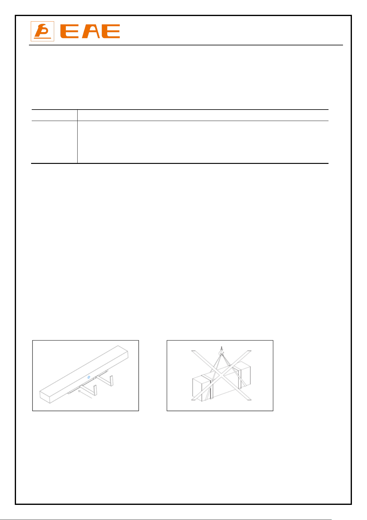
2.3 Lifting and handling............................................................................................................................................................... 8
PRODUCTS DESCRIPTIONS ...................................................................................................................................................9
3.1 General descriptions ............................................................................................................................................................. 9
3.2 Construction of the lift .......................................................................................................................................................... 9
3.3 Dimensions.......................................................................................................................................................................... 10
3.4 Safety devices descriptions ................................................................................................................................................. 11
3.5 Technical data ..................................................................................................................................................................... 12
3.6 Nameplate........................................................................................................................................................................... 12
INSTALLATION INSTRUCTIONS ...........................................................................................................................................13
4.1 Preparations before installation ......................................................................................................................................... 13
4.2 Installation attentions ......................................................................................................................................................... 16
4.3 General installation steps.................................................................................................................................................... 16
4.4. Items to be checked after installation ............................................................................................................................... 26
OPERATION INSTRUCTIONS ...............................................................................................................................................26
5.1 Precautions ......................................................................................................................................................................... 26
5.2 Descriptions of control panel .............................................................................................................................................. 27
5.3 Operation instructions ........................................................................................................................................................ 27
5.4 Emergent lowering in case of no power supply .................................................................................................................. 29
TROUBLE SHOOTING..........................................................................................................................................................30
MAINTENANCE ..................................................................................................................................................................31
Annex 1, Steel cable connection ............................................................................................................................................... 33
Annex 2, Electrical schemes and parts list ................................................................................................................................ 34
Annex 3, Hydraulic schemes and parts list................................................................................................................................ 40
Annex 4,Exploded drawings and parts list ................................................................................................................................ 44

Installation, Operation and Parts Manual
EE-6435BWF
4
SAFETY NOTES
1.1 Operation of lifting platforms
This lift is specially designed for lifting motor vehicles. Users are not allowed to use it for any other purposes. The applicable national
regulations, laws and directives must be observed.
Only users aged 18 or above who have been instructed on how to operate the lifting platform and have proven their ability to do so to the
owner are to be entrusted with unsupervised operation of lifting platforms. The task of operating the lifting platforms must be granted in
writing.
Before loading a vehicle onto the lifting platform, users should study the original operation instructions and familiarize themselves with the
operating procedures in several trial runs.
Lift vehicle within the rated load. Don’t attempt to raise vehicles with excessive weight.
1.2 Checking of the lifting platforms
Checks are to be based on the following directives and regulations:
Basic principles for testing lifting platforms
The basic safety requirements stipulated in the directive 2006/42/EC
The applicable accident prevention regulations
The checks are to be organized by the user of the lifting platform. The user is responsible for appointing an expert or qualified person to
perform checking. It must be ensure that the person chosen satisfies the requirements.
The user bears special responsibility if employees of the company are appointed as experts or qualified persons.
1.2.1 Scope of checking
Regular checking essentially involves performing a visual inspection and a functional test. This includes checking the condition of the
components and equipment, checking that the safety systems are complete and functioning properly and that the inspection log book is
completely filled in. The scope of exceptional checking depends on the nature and extent of any structural modification or repair work.
1.2.2 Regular checking
After initial commissioning, lifting platforms are to be checked by a qualified person at intervals of no longer than one year.
A qualified person is somebody with the training and experience required to possess sufficient knowledge of lifting platforms and who is
sufficiently familiar with the pertinent national regulations, accident prevention regulations and generally acknowledged rules of
engineering to be able to assess the safe operating condition of lifting platforms.
1.2.3 Exceptional checking
Lifting platforms with a lift height of more than 2 meters and lifting platforms intended for use with people standing under the load
bearing elements of the load are to be checked by an expert prior or reuse following structural modifications and major repairs to load
bearing components.
An expert is somebody with the training and experience required to possess specialist knowledge of lifting platforms and who is
sufficiently familiar with the pertinent national work safety regulations, accident prevention regulations and generally acknowledged rules
of engineering to be able to check and give an expert option on lifting platforms.

Installation, Operation and Parts Manual
EE-6435BWF
5
1.3 Important safety notices
1.3.1 Recommend for indoor use only. DO not expose the lift to rain, snow or excessive moisture.
1.3.2 Only use this lift on a surface that is stable, level and dry and not slippery, and capable of sustaining the load. Do not install the lift on
any asphalt surface.
1.3.3 Read and understand all safety warnings before operating the lift.
1.3.4 Do not leave the controls while the lift is still in motion.
1.3.5 Keep hands and feet away from any moving parts. Keep feet clear of the lift when lowering.
1.3.6 Only these properly trained personnel can operate the lift.
1.3.7 Do not wear unfit clothes such as large clothes with flounces, tires, etc, which could be caught by moving parts of the lift.
1.3.8 To prevent evitable incidents, surrounding areas of the lift must be tidy and with nothing unconcerned.
1.3.9 The lift is simply designed to lift the entire body of vehicles, with its maximum weight within the lifting capacity.
1.3.10 Always insure the safety locks are engaged before any attempt to work near or under the vehicle. Never remove safety related
components from the lift. Do not use if safety related components are damaged or missing.
1.3.11 Do not rock the vehicle while on the lift or remove any heavy component from vehicle that may cause excessive weight shift.
1.3.12 Check at any time the parts of the lift to ensure the agility of moving parts and the performance of synchronization. Ensure regular
maintenance and if anything abnormal occurs, stop using the lift immediately and contact our dealers for help.
1.3.13 Lower the lift to its lowest position and do remember to cut off the power source when service finishes.
1.3.14 Do not modify any parts of the lift without manufacturer’s advice.
1.3.15 If the lift is going to be left unused for a long time, users are required to:
a. Disconnect the power;
b. Empty the oil tank;
c. Lubricate the moving parts with hydraulic oil.
WARNING:The warnings, cautions and instructions discussed in this instruction manual cannot cover all possible conditions and
situations that may occur. It must be understood by the operator that common sense and caution are factors which cannot be built into
this product, but must be supplied by the operator.
Attention: For environment protection, please dispose the disused oil in a proper way.

Installation, Operation and Parts Manual
EE-6435BWF
6
1.4 Safety duties
All safety warning labels are clearly depicted on the lift to ensure that the operator is aware of and avoid the dangers
of using the lift in an incorrect manner. The labels must be kept clean and they have to be replaced if detached or
damaged. Please read carefully the meaning of each label and memories them for future operation.
CAUTIONS
-·Read and digest the complete operation instructions before operating the lift.
- This lift is designed to raise the entire body of the intended vehicles. Don’t use it for other purposes.
- Inspect the space above and below the load and the loading carrying devices. It shall be free of obstructions before operating.
- Before raising operation, run the lift without load for a complete cycle to ensure it is in good condition.
- The supporting pads must be placed to pick-up points recommended by vehicle manufacturers. (Only for chassis supporting lift)
- Before lifting the vehicle and during all operations on the vehicle, make sure that it is properly stopped by the hand brake.
- Check the vehicle after raising a short distance to ensure that it is correctly and safely positioned.
- The load carrying device shall be observed by the operator throughout the motion of the lift.
- Engage the safety locking mechanism before entering under the raised vehicle.
WARNINGS
- ONLY authorized persons are permitted in the lift area.
- Always remember to use safety stands before removing or installing heavy parts. (Only for chassis supporting lift)
- Avoid excessive rocking of vehicle while on the lift
- Do not climb onto the load or load carrying device when they are raised.
DANGERS
- It is forbidden for people to stand in the field of motion during raising or lowering movement.
- Do not try to raise the vehicle with excessive length or width. Otherwise there is risk of vehicle falling from lift.
- Do not try to remove, interrupt or modify the safety devices.
- Electrical connection and maintenance must be done by qualified electricians, otherwise there could be danger of electric shock.
The instructions, cautions and warnings written above as well as in the in Manual cannot cover all possible conditions and situations
that may occur. The Common sense for safety must be always in the mind of the operator. For damages caused through willful
misconduct or gross negligence, the lift manufacturer or its distributors are excluded of liability.

Installation, Operation and Parts Manual
EE-6435BWF
7
1.5 Potential risks and safety measures
1.5.1 RISK OF CRUSHING
Safety measures:
-During lift functioning, the operator must remain at the control station
-The presence of persons beneath the crossbeams and/or the platforms when they are moving, or the presence of persons inside the
danger zone indicated in the following figure is strictly prohibited.
-During operations persons are admitted to the area beneath the vehicle only when the vehicle is already in the elevated position, when
the crossbeams and platforms are stationary, and when the mechanical safety devices are engaged
-When the platforms (and vehicle) are lowering the operator must never be partly or completely underneath or near of the movable
structure.
-The lift operator must not start the lift until it has been clearly established that there are no persons in danger zone.
1.5.2 RISK OF IMPACT
Caused by the parts of the lift or the vehicle that are positioned at head height.
Safety measure:
Personnel must be careful to avoid impact with parts of the machine not marked with special colors.
1.5.3RISK OF VEHICLE MOVING
Caused by operations involving the application of force sufficient to displace the vehicle.
In the case of large or particularly heavy vehicles, sudden movement could create an unacceptable overload or uneven load sharing.
Safety measure:
Make sure that the vehicle is properly stopped by the hand brake before being raised.
1.5.4RISK OF VEHICLE FALLING FROM LIFT
This hazard may arise in the case of incorrect positioning of the vehicle on the platforms, incorrect stopping of the vehicle, or in the case of
vehicles of dimensions that are not compatible with the capacity of the lift.
Safety measure:
Check the vehicle after raising a short distance to ensure that it is correctly and safely positioned.
1.5.5RISK OF SLACKENING OF LIFT CABLES
Caused by objects left leaning against the posts or on the platforms.
Safety measure:
Inspect the space above and below the load and the loading carrying devices. It shall be free of obstructions before operating.
1.5.6RISK OF SLIPPING
Caused by lubricant contamination of the floor around the lift.
Safety measure:
The area beneath and surrounding the lift and also the platforms must be kept clean. Remove any oil spills immediately.
1.6 Noise level
Noise emitted during operating the lift should be less than 70dB (A). For your health consideration, it is suggested to place a noise
detector in your working area.

Installation, Operation and Parts Manual
EE-6435BWF
8
PACKING, STORAGE AND TRANSPORTATION
Packing, lifting, handling, transporting operations must be performed only by experienced personnel with
appropriate knowledge of the lift and after reading this manual.
2.1 The lift was dismantled into the following 2 parts for transportation
Name
Packed by
Dimension(mm)
Weight(kg)
Quantity
Lift
(
48L
)
Steel brackets
4950*740*900
About 1550
1
Lift
(
52L
)
Steel brackets
5350*740*900
About 1750
1
Lift
(
57L
)
Steel brackets
5850*740*900
About 2000
1
Ramps
Bubbled film
1500*570*180
45
2
2.2 Storage
The packs must be kept in a covered and protected area in a temperature range 0f -10℃to +40℃. They must not be exposed to direct
sunlight, rain or water.
Stacking the packs
We advise against stacking because the packs are not designed for this type of storage. The narrow base, heavy weight and large size of
the packs make stacking difficult and potentially dangerous.
If stacking is unavoidable, use all appropriate precautions:
-never stack to more than 2 meters in height.
-never make stacks of single packs. Always stack pairs of packs in a cross pattern so that the base is bigger and the resulting stack is more
stable. Once the stack is complete, restrain it using straps, ropes or other suitable methods.
A maximum of two packs can be stacked on lorries, in containers, and in railway wagons, on condition that the packs are strapped
together and restrained to stop them falling.
2.3 Lifting and handling
The packs can be lifted and transported only by using lift trucks.
The center of gravity and lashing points are marked on the packaging.
Never attempt to hoist or transport the unit using lifting slings.
Opening the packs
When the lift is delivered make sure that it has not been damaged during transportation and that all the parts specified on the packing list
are present.
Packs must be opened adopting all the precautions required to avoid injury to persons (keep at a safe distance when cutting the straps) or
damage to parts of the machine (be careful that no parts are dropped while you are opening the packing)
Take special care with the hydraulic power unit, the control panel and the platform cylinder.

Installation, Operation and Parts Manual
EE-6435BWF
9
PRODUCTS DESCRIPTIONS
3.1 General descriptions
This four post lift is generally composed by four posts, two beams, two platforms, a hydraulic oil cylinder and a set of power unit. It is
driven by an electro-hydraulic system. Up and down of platforms is controlled by the to and fro movement of the oil cylinder. To ensure
safety for operators, it is equipped with mechanical safety locks in the four posts , which will automatically engaged in the process of lifting
so as to prevent the platforms from sudden dropping down in case the hydraulic system fails to work.
3.2 Construction of the lift
1. Power side post 2.Post 3.Power side crossbeam 4.The secondary crossbeam 5.Main platform
6. The secondary platform 7.main platform of the wheel free lift 8. The secondary platform of the wheel free lift
9. Side slip 10. Drive-on ramps 11. Control box 12.Power unit 13.Turntabl (optional) 14. Motor housing

Installation, Operation and Parts Manual
EE-6435BWF
10
3.3 Dimensions
DATA
MODEL
48L
52L
57L
RL
4880 (192 1/8”)
5280 (207 7/8”)
5780 (227 9/16”)
OL
5970 (235 1/16”)
6370 (250 13/16”)
6870 (270 1/2”)
CL
4888 (192 7/16”)
5288 (208 3/16”)
5788 (227 7/8”)
CL1
4438 (174 3/4”)
4838 (190 1/2”)
5338 (210 3/16”)
L1
1580 (62 3/16”)
1980 (77 15/16”)
2280 (89 3/4”)
L2
970 (38 1/8”)
970 (38 1/8”)
1170 (46”)

Installation, Operation and Parts Manual
EE-6435BWF
11
3.4 Safety devices descriptions
NO.
Safety Device
Function
1
Safety rod
Ensure mechanical safety in the rising and lowering process and lock the
lifting platform at expected height.
2
Safety block A
3
Safety block B
4
Electromagnet
Release the mechanical locking unit.
5
Limit switch
Disconnect operation power in case of slacken steel cables.
6
Max height limit switch
Control max rising height and protect the oil cylinder.
7
Descent limit switch
Make the platform stop lowering at safety height so as to guard against
pinching or shearing. Push the other button (DOWN II) to lower the runway
completely.
8
Height limit switch of the wheel free lift
Control the rising height and protect the oil cylinder of the wheel free lift.
9
Front wheel retainer
Prevent the vehicle from rolling off.
10
Drive-on ramps
The wheel retainer functions when the platform is lifted.
11
Tip-off protection for the wheel free lift
Protect lifting platform from tipping-up, in case of unbalanced loading.

Installation, Operation and Parts Manual
EE-6435BWF
12
3.5 Technical data
Item
Data
Power Form
Electro-hydraulic
Rated capacity of the lifting platform
4000kg(48L/52L), 5000kg (48L/52L/57L)
Full rise height of the main lift
1850mm
Initial height of the main lift
225mm
Full rise time of the main lift
≤60S
Full lowering time of the main lift
30-40S
Rated capacity of the wheel free lift
4000kg
Rising height of the wheel free lift
450mm
Working pressure
Main lift ≥18MPa;wheel free lift ≥21MPa
Electricity
380V/400V/415V-3PH-50HZ or 60HZ
Motor
2.2 /3.0/3.5kW
Hydraulic oil
12L, 46# hydraulic oil
Noise
< 75dB(A)
3.6 Nameplate
The nameplate is fixed beneath the oil tank
Check the work voltage and the lift capacity printed on the name plate.
Do not lift vehicles with weight beyond the capacity.
S/N and production date could be helpful for future service.

Installation, Operation and Parts Manual
EE-6435BWF
13
INSTALLATION INSTRUCTIONS
4.1 Preparations before installation
4.1.1 Space requirements.
Refer to 3.3 for the dimensions of the lift. There must also be a clearance of at least 0.6 meter between the lifting platform and fixed
elements (e.g. wall) in all lifting positions. There must be sufficient space at the ends of the lifting platform for driving vehicles on and off.
To stop vehicles colliding with the ceiling, it is advisable to fit an overhead light barrier in low ceiling buildings.
4.1.2 Foundations and connections
The user must have the following work performed before erecting the lift.
Construction of the foundation following consultation with the manufacturer’s customer service or an authorized service agent.
Routing of the wiring to the installation location. The user must provide fuse protection for the connection. Electrical system
connection must be done by qualified electricians. Requirements for power supply cable of the installation site: at least 2.5mm2
wire core for 3Ph power and 4.0mm2 wire core for 1Ph power.
Foundations preparations
Indoor installation only.
There must also be a clearance of at least 0.6 meter between the lifting platform and fixed elements (e.g. wall) in all lifting positions.
There must be sufficient space for driving vehicles on and off.
C20/25 concrete foundation with a minimum thickness of 200mm.

Installation, Operation and Parts Manual
EE-6435BWF
14
Surface under the base of post: Horizontal and even (Gradients max. 0.5 %)
Newly built concrete ground must be older than 20days.
In mm.
Platform length
L
48L
4888 (192 7/16”)
52L
5288(208 3/16”)
57L
5788(227 7/8”)

Installation, Operation and Parts Manual
EE-6435BWF
15
4.1.3 Tools and equipment needed for installation
Tool name
Specification
Quantity
Electrical driller
1
Drill bit
D18 and D20 (L=350mm)
1
Open end spanner
D17-19
2
Open end spanner
D22—24
1
Adjustable wrench
>D30
1
Hex socket spanner kits
M3 to M10
1
Torque spanner
MD400
1
Spline end spanner kits
D24—27
1
Phillips screwdriver
PH2
1
Flat Tip screwdrivers
PH2
1
Knife
1
Plumb
this is for levelling
1
Crowbar
40cm
1
Needle Nose Pliers
1
Hammer
4pounds/10 pounds
1
Circlip Pliers
1
4.1.5 Checking parts
Unfold the package and check if any parts missed as per the following list. Do not hesitate to contact us in case any parts missed, but if you
do not contact us and insist installing upon the lack of some parts, we as well as our dealers will not bear any responsibility for this and will
charge for any parts subsequently demanded by the buyer.
S/N
Name
Qty
1
Platform A
1
2
Platform B
1
3
Power side post
1
4
Post
3
5
Power side crossbeam
1
6
The opposite crossbeam
1
7
Front wheel retainer
2
8
Power unit
1
9
Control unit
1
10
Slider
8
11
Slider holder
8
12
Protective cover
4
13
Post cap
4
14
Ramp shaft
2
15
Expansion bolt M16*120
16

Installation, Operation and Parts Manual
EE-6435BWF
16
S/N
Name
Qty
16
Hex head full swivel screw M12*30
4
17
Hex socket flat head screw M12*80
8
18
Hex head full swivel screw M10*35
4
19
Hex socket button head screw M8*16
20
20
Spring washer Ø 10
4
21
Hex nut M10
4
22
Hex nut M12
4
23
Hex nut M20
12
24
Cotter pin 2.5*30
4
25
Flat washer Ø 10
4
26
Flat washer Ø 8
20
27
Anti-shock pad
4
28
Cross socket cap head screw M4*14
2
29
Manual
1
30
Drive-on ramp
2
4.2 Installation attentions
4.2.1 Joints of oil hose and wiring must be firmly connected in order to avoid leakage of oil hose and looseness of electrical wires.
4.2.2 All bolts should be firmly screwed up.
4.2.3 Do not place any vehicle on the lift in the case of trial running.
4.3 General installation steps
ONLY TRAINED AND QUALIFIED INSTALLERS CAN PERFORM LIFT INSTALLATION DUTIES.
Step 1: Ascertain the layout dimensions.
Mark the four positions for base plate of the four posts by a tape measure and chalk.
Ensure two diagonal lines are of the same length.

Installation, Operation and Parts Manual
EE-6435BWF
17
Step 2: Remove the packing materials.
1.Prepare 4 wooden battens with thickness being more than 100mm and length being more than 700mm. (other dependable devices may
also applicable). Forklift the packing rack onto two of the battens so as to make its base be clear off the ground.
2. Have the upper platform suspended by the forklift, screw off the corresponding bolts that fixed with the packing racket and remove the
upper platform onto the rest two battens.
3. Screw off the under bolts and take away the packing racks at both sides.
4. Remove the packing film.
Attention: Take care and avoid scratching the painting and hoses.
Step 3: Position four posts and two crossbeams.
Place four posts to standing positions as per the layout dimensions.
Put parts like control unit, power unit, tank chain, post caps and protective covers aside.
Move the rest two crossbeams in the direction of the arrows indicated in the following scheme.
CAUTION: Make sure to read and understand before trying to remove the crossbeams.
Otherwise, there is a risk of damaging the steel ropes.
1.Power side post
2.Post
3.Main platform
4.Secondary platform
5.Main crossbeam
6.Secondary crossbeam
7.Oil-supply hose for the main lift
8. Oil-return hose
9. Oil-supply hose for the master
cylinder of the wheel free lift
10. Oil-supply hose for the slave
cylinder of the wheel free lift

Installation, Operation and Parts Manual
EE-6435BWF
18
Pull oil hoses No.7 and No.8 from the main platform and make them go through the right side hole reserved at the crossbeam.
(The hose No.7 has a right-angled fitting.)
Pull hoses No.9 and NO.10 from the secondary platform and make oil hose NO.9 go through the left side hole reserved at the crossbeam.
(The hose No.9 has a right-angled fitting. The hose No. 10 has an angled fitting with 45 degree.)
Step 4: Assemble crossbeams onto both ends of the platforms.
1. Align the two platforms at both ends and keep a distance about 1025mm between them (excluding the width of the two tracks for
rolling jacks)
2. Connect the crossbeam and the lifting platform using hex socket flat head screws (M12*80). Tighten all the screws only after two
crossbeams are well fit with the two platforms. Use proper lifting device to move the corresponding platform, in the case the screw holes
are not well aligned.
Step 5: Install posts and ratchets of the mechanical locking device.
1. Pull the safety ratchet (NO.12) through the hole on the top of the post until the other end of the ratchet is above the end of crossbeam.
(Use proper devices to keep the four ratchets stay above the ends of crossbeam as indicated in the following fig.)
3.Main platform
4.Secondary platform
5.Main crossbeam
6.Secodnary platform
11.M12*80 Hex socket flat head screw
1.Powerside post
2.Post
12.Safety ratchet

Installation, Operation and Parts Manual
EE-6435BWF
19
2. Push the power side post to the direction of the crossbeam and insert the ratchet down through the inner surface of the end plates of
the crossbeam. (Take special care not to damage the limit switch NO.13 in the following fig.)
Step 6: Route and fix steel ropes.
Please see Annex 1 for steel cable routing.
Inspect and make the rope be in the slot of the two pulleys (NO.15 and NO.16 in the following fig.)
Pull the rope (NO.14) up through the hole reserved on top of the post and fix it with screws.
(Attention: Fix with two M20 nuts (NO.17) and oneφ20 flat washer (NO.18) above the top plate.
Fix with one M20 nut and one φ20 flat washer under the top plate.)
12. Safety ratchet
13. Limit switch (for safe descent )
14.steel rope
15.pulley A
16.small pulley
17.M20 nut
18.φ20 flat washer

Installation, Operation and Parts Manual
EE-6435BWF
20
Step 7: Install holders for sliding blocks, fix protective covers and fix the other end of the safety ratchets.
1. Make the holder (NO.19) for sliding block be hooked with folded edge of the post and fix it with the crossbeam using M8*12 hex socket
button head screw (NO.20).
2. Fix the protective cover (NO.22) with the crossbeam using M8*12 hex socket button head screw (NO.20).
3. Fix the other end of the safety ratchet at bottom of the post using M8*20 hex socket button head screw (NO.23)
Step 8: Install control and power unit.
1. Firstly, fix the control unit (NO.24) with its installation kit (NO.25) using M6*15 hex socket cylinder head screw (NO.26) and M6 nut
(NO.27).
After that install the control unit onto the power side post using M6*15 hex socket cylinder head screw (NO.26) and M6 nut (NO.27).
2. Fix the plate for hanging power unit (NO.28) onto the side opposite to the control unit and fix the power unit onto the hanging plate as
indicated in the following fig.
24. Control unit
30.M10*35 hex head screw
25.Installation kit for control unit
31.M10 hex nut
26.M6*15 hex socket cylinder head screw
32.φ10 spring washer
27.M6 nut
33.φ10 flat washer
28. Plate for hanging power unit
34. Anti-shock pad
29.power unit
19. Holder for sliding block (including sliding block)
20. Hex socket button head screw M8*12
21. Flat washer φ8
22. Protective cover
23. Hex socket button head screw M8*20
Other manuals for EE-6435BWF
1
Table of contents
Other EAE Lifting System manuals