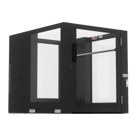
Ascension 5442P Operating instructions

MAINTENANCE & REPAIR
MANUAL
ASCENSION PROTEGE
PORTABLE WHEELCHAIR LIFT
MODEL 5442P
Patented – see www.ascension-lift.com/patents
By Philip Brobeck at 11:20 am, Dec 21, 2018


ASCENSION PROTEGE
PORTABLE WHEELCHAIR LIFT
MODEL 5442P
MAINTENANCE & REPAIR
MANUAL

Copyright © 2018 Ascension, a Division of AGM, Tucson, Arizona
This document, or parts thereof, may not be reproduced in any form, by any method, for
any purpose, without written the permission of Ascension.

TABLE OF CONTENTS
INTRODUCTION ............................................................................................................. 1
About This Manual ..................................................................................................... 1
Additional Information ................................................................................................ 2
Getting Help ............................................................................................................... 2
Contacting Ascension ................................................................................................ 2
SECTION 1 Terminology ............................................................................................... 3
SECTION 2 Routine Maintenance ................................................................................. 5
2.1 Hydraulic System ............................................................................................ 5
2.2 Cleaning .......................................................................................................... 5
SECTION 3 Mechanical Disassembly and Repair ......................................................... 6
3.1 Important Preliminary Information ................................................................... 6
3.2 Electrically Isolating the Lift ............................................................................. 6
3.3 Removing the Sheet Metal Skins .................................................................... 7
3.4 Operating Stations .......................................................................................... 8
3.5 On/Off Switch .................................................................................................. 9
3.6 Upper Stop Sensor .......................................................................................... 9
3.7 Lower Terminal Switch .................................................................................. 11
3.8 Upper Platform Gate Switch .......................................................................... 12
3.9 Front Gate Interlock Switch ........................................................................... 13
3.10 Tilt Sensor ..................................................................................................... 15
3.11 Hydraulic Valves ........................................................................................... 16
3.12 Windows........................................................................................................ 18
3.13 Platform Floor Removal ................................................................................ 19
3.14 Lower Gate Closer Adjustment ..................................................................... 21
3.15 Upper Gate Closer Adjustment ..................................................................... 23
3.16 Safety Pan Switches ..................................................................................... 25
3.17 Safety Pan Removal ..................................................................................... 27
SECTION 4 Electrical Testing ..................................................................................... 29
4.1 Access to the Electrical Panel ....................................................................... 32
4.2 Testing the Switches ..................................................................................... 33

4.3 Testing the Smart Relay ................................................................................ 34
4.4 Testing the Power Supply ............................................................................. 35
4.5 Testing the Power Relay ............................................................................... 35
SECTION 5 Lift Compression/Expansion .................................................................... 37
5.1 Compressing the Lift ..................................................................................... 38
5.2 Expanding the Lift ......................................................................................... 42
5.3 Verification of Operation ................................................................................ 45
SECTION 6 Troubleshooting ....................................................................................... 46

Maintenance & Repair Manual Introduction
PROTEGE 5442P
1 112510 REV H
INTRODUCTION
The purpose of this manual is to provide the necessary information to perform
maintenance and repairs on the Ascension PROTEGE portable wheelchair lift. This
manual is intended to be used by skilled technicians who have experience working on
electro-mechanical systems and devices. Furthermore, these personnel should be well-
versed in standard industrial safety practices and procedures. The appropriate sections
should be read through completely before any repairs are begun.
About This Manual
This manual is divided into six sections:
Section 1 defines terms that are used throughout the remainder of this manual.
Section 2 describes the recommended procedures for performing routine maintenance.
Section 3 covers mechanical repair. This includes component replacement, as well as
detailed procedures to disassemble, test, and reassemble major components.
Section 4 covers electrical testing.
Section 5 describes how to compress the lift so that it can be rolled through a narrow
doorway and then expanded again for normal use.
Section 6 is a troubleshooting guide. It provides information for locating and correcting
any problems with the lift.

Maintenance & Repair Manual Introduction
PROTEGE 5442P
2 112510 REV H
Additional Information
The following sources of information supplement this manual:
Operating Manual An Operating Manual is supplied with each lift and includes all the
necessary information to set up, break down, store, and transport the lift. It also
includes the general safety precautions that should be observed.
Setup and Operation Video A short video on setup and operation can be found at the
following web address: https://ascension-lift.com/lift-setup/.
Getting Help
If you have a question or problem with the lift, please try to find the solution in this
manual. In particular, be sure to review the troubleshooting guide in Section 6. If you
are not able to resolve the problem, please contact Ascension as indicated below,
making sure that you have the serial number of your lift ready. The serial number can
be found on the data plate located inside the platform on the upper right rail. Also, it is
recommended that you contact Ascension while in the immediate vicinity of your lift, as
this will reduce the time required to properly diagnose the problem.
Contacting Ascension
Ascension's business hours are 8 a.m. to 5 p.m. Mountain Standard Time, Monday
through Friday.
Telephone: 800-459-0400 Mailing Address: Ascension
Fax: 520-881-4983 Customer Service
Website: www.ascension-lift.com Tucson, AZ 85717-0020

Maintenance & Repair Manual SECTION 2
PROTEGE 5442P
3 112510 REV H
SECTION 1 Terminology
To effectively use this manual, you need to be familiar with the following terms. Refer to
the figure on the following page for identification of components. Not all components
are shown in the figure.
Access Panel The hinged panels (four total) that provide access to the machinery
cabinets.
Back End The end of the lift where the upper landing gate is located.
Base The steel frame that rests on the floor when the casters are removed and
supports the operating mechanism.
Control Panel The electrical panel for the lift which contains the power supply, control
system relay, and the main power relay. The control panel is located inside the right-
hand machinery cabinet.
Dock Plate The hinged plate that bridges the gap between the platform floor and the
upper landing surface when the platform is at the upper landing.
Front End The end of the lift where the lower landing gate is located.
Lower Landing Gate The gate that serves the lower landing (ground level).
Machinery Cabinet The enclosures in which the lifting and control mechanisms are
located. There is one cabinet on each side of the lift. The contents of the machinery
cabinets are accessible through the access panels.
Operating Stations The controls for raising and lowering the platform. All three
operating stations are located on the right side of the platform. The operating station
inside the platform has an emergency stop switch.
Platform The compartment in which the passenger rides.
Skins The sheet metal panels that enclose the operating machinery.
Upper Landing The stage, platform, or riser that the lift serves.
Upper Landing Gate The gate that serves the upper landing, or stage.

Maintenance & Repair Manual SECTION 2
PROTEGE 5442P
4 112510 REV H

Maintenance & Repair Manual SECTION 2
PROTEGE 5442P
5 112510 REV H
SECTION 2 Routine Maintenance
2.1 Hydraulic System
The fluid level of the hydraulic system should be checked every six months. Before
checking the fluid level, make sure the platform is at ground level (i.e., at the lower
landing) and off its casters. Then open one of the access panels in the right-hand
machinery cabinet and verify that the fluid level in the reservoir is between the min-max
marks on the reservoir.
Inspect the condition of the hydraulic fluid. Change the fluid if it has darkened, appears
dirty, or has a strong acrid or burnt odor.
If you need to add hydraulic fluid to the lift, use an ISO 32 grade hydraulic oil, such as
Texaco Rando® HD32 or 76 Unax AW32 filtered to 10 microns. The reservoir cap is
located just above the min-max marks on the reservoir. Remove the cap and use a
funnel and rubber hose to add hydraulic fluid to the reservoir.
2.2 Cleaning
All parts of the lift except the windows may be cleaned with soap and water or general
purpose household cleaners. Use a sponge or soft cloth dampened with cleaning
solution. Wipe dry with a cloth after cleaning. Do not expose any part of the lift to a
direct liquid stream or spray, such as from a water hose.
To clean the windows, Windex® or Formula 409® brand window cleaners may be used.
To remove scratches, Plastic Polish 2 or 3 is recommended. Plastic Polish is available
from Novus, Inc., Minneapolis, Minnesota, item numbers PC-20 and PC-30 respectively.

Maintenance & Repair Manual SECTION 3
PROTEGE 5442P
6 112510 REV H
SECTION 3 Mechanical Disassembly and Repair
3.1 Important Preliminary Information
The repairs in this section are to be performed by a skilled technician who has
experience working on electro-mechanical systems. Furthermore, the technician should
be well-versed in standard industrial safety practices and procedures. In the United
States of America, electrical safety procedures are established in OSHA's
Lockout/Tagout – Hazardous Energy Sources Standard (29 CFR 1910.147).
Familiarity with the setup and operation of the lift is required to effectively perform the
repairs listed in this section. This information can be found in the Operating Manual
provided with the lift.
3.2 Electrically Isolating the Lift
This section describes the procedures for electrically isolating the lift, which is
necessary in order to safely perform some of the repairs covered in this manual.
To electrically isolate the lift, perform the following steps in the order listed:
1. Turn the disconnect switch in the power cord to the ‘OFF’ position. Secure it with a
lockout hasp and/or padlock.
OR
1. Remove the lift’s power cord from the wall outlet.
2. Attach a DANGER tag to the end of the power cord and lock out the cord according
to the procedures established in OSHA's Lockout/Tagout – Hazardous Energy
Sources Standard (29 CFR 1910.147).
3. Coil the electrical cord and place it inside the platform.

Maintenance & Repair Manual SECTION 3
PROTEGE 5442P
7 112510 REV H
3.3 Removing the Sheet Metal Skins
For some of the repairs described in this manual, it is necessary to gain access to the
inner components of the lift beyond what is possible with the sheet metal "skins" still on
the lift. The figure below shows the skins and their positions.
All of the skins are attached to the frame with screws that can be removed with a
Phillips screwdriver. Additionally, it may be necessary to remove the grab bar or a
window first before removing some of the skins. To remove the grab bar, remove the
Phillips head screws that secure it to the lift. To remove a window, refer to Section
3.12.

Maintenance & Repair Manual SECTION 3
PROTEGE 5442P
8 112510 REV H
3.4 Operating Stations
The operating stations house the UP/DOWN rocker switches and, on the station inside
the platform, the emergency stop button. To test or remove either of these switches,
use a Phillips screwdriver to remove the two (2) screws that secure the switch plate to
the platform and pull the plate away from the platform. A standard multi-meter can be
used to test the switches.
To remove the rocker switch, depress the mounting tabs and push the switch out of its
mounting cutout.
To remove the emergency stop button, use the release lever on the contact block to
disengage the block from the back of the operator then pull it off. Remove the mounting
nut to free the operator from the switch plate.

Maintenance & Repair Manual SECTION 3
PROTEGE 5442P
9 112510 REV H
3.5 On/Off Switch
The On/Off rocker switch may be set to ‘OFF’ to prevent operation of the lift at the
owner’s discretion. The lift will only operate when the switch is set to ‘ON.’
The On/Off rocker switch is located in the right side machinery cabinet across from the
motor. To remove it, remove the (2) screws fastening the sheet metal switch mounting
bracket to the lift frame and snap the switch out of the bracket.
3.6 Upper Stop Sensor
The upper stop sensor sets the height at which the platform stops at the upper landing.
This section describes the procedures for adjusting the upper stop sensor in the case
that it has come out of adjustment. If you are only looking for instructions on setting up
the lift to stop at the correct height, refer to the section titled "Setup Instructions" in the
Operating Manual.

Maintenance & Repair Manual SECTION 3
PROTEGE 5442P
10 112510 REV H
The optical beam must always pass through the area marked with the yellow decal,
shown in the figure above. The following procedure can be used if the optical sensor is
misaligned:
1. Remove the outer left sheet metal skin to gain access to the height sensor.
2. To adjust vertical alignment, loosen the two (2) screws holding the sensor bracket to
the frame and shift the sensor bracket until the beam passes through the area
marked with the yellow decal.
3. To correct horizontal alignment, gently bend the sensor bracket until the beam
passes through the area marked with the yellow decal.
The platform should stop when the optical beam strikes the lower edge of the optical
reflector. If the platform does not stop correctly, it may be necessary to adjust the gain
on the optical sensor so that the platform stops when the beam strikes the optical
reflector. The gain is a small black dial on the sensor (see the figure on the previous
page) that can be adjusted with a small standard screwdriver.

Maintenance & Repair Manual SECTION 3
PROTEGE 5442P
11 112510 REV H
3.7 Lower Terminal Switch
The lower terminal switch notifies the controller that the platform has reached ground
level. It is actuated by the right vertical guide rail when the platform is less than 0.5
inches [13 mm] above the ground, which allows for the front gate to be opened and
makes sure the lift stops properly when it reaches the ground.
The lower terminal switch can be accessed by removing the right sheet metal cap (see
Section 3.3) and is located near the vertical guide rail. To remove the lower terminal
switch for testing, use a Phillips screwdriver to remove the two (2) screws holding its
bracket to the platform frame. It is of the normally open (NO) type and can be tested
with a standard multi-meter.

Maintenance & Repair Manual SECTION 3
PROTEGE 5442P
12 112510 REV H
3.8 Upper Platform Gate Switch
The upper platform gate switch detects whether the upper platform gate is open or
closed. The switch is only visible with the machinery cabinet sheet metal skin on the
handle side of the gate removed, and is located on the lift frame about 26" [660 mm]
from the platform floor. Refer to the figure below. The switch is of the normally open
(NO) type and can be tested with a standard multi-meter.
The upper platform gate switch is in correct adjustment if the platform will operate only
when the gate is closed. The switch itself can only have its position adjusted by using a
Phillips screwdriver to loosen the two (2) screws on the bracket and by sliding it to either
side.
To remove the switch, first remove the machinery cabinet sheet metal skin on the
handle side of the gate (see Section 3.3). Then, using a 1/16" hex key, remove the two
(2) cap screws holding the switch to its bracket. Finally, disconnect the Molex connector
at the end of the switch harness.

Maintenance & Repair Manual SECTION 3
PROTEGE 5442P
13 112510 REV H
3.9 Front Gate Interlock Switch
The front (lower landing) gate is equipped with an interlock switch performs two
functions: first, it prevents the lift from operating unless the gate is closed and locked,
and second, it prevents the gate from being opened while the lift is in use. The interlock
switch is visible only when the front post cover on the handle side of the gate is
removed. Refer to the figure below for its location.
The interlock switch includes a safety circuit that closes only when the gate is closed
and locked, as well as a secondary circuit that closes when the gate is closed
(regardless of the state of the lock contacts). The locking pin inside the switch is
engaged by a spring, and unlocks when the solenoid is energized. The interlock
actuator may be inserted even when the solenoid is de-energized.
The solenoid is only energized to unlock the gate when the platform is at the lower
landing (determined by the lower terminal switch; see Section 3.7). If the platform is at
the lower landing and the gate is locked, press "Down" on an operating switch to unlock
the gate.

Maintenance & Repair Manual SECTION 3
PROTEGE 5442P
14 112510 REV H
To remove the interlock switch, perform the following steps:
1. Remove the front and rear sheet metal covers on the strike side of the gate.
2. Disconnect the Molex connector that is wired to the interlock switch.
3. Remove the (2) flat head screws fastening the interlock through the back of the
frame tube. Take care to ensure that the (2) lock nuts holding the front of the
interlock do not drop into the lift frame when the screws are removed.
4. Pull the interlock out of the lift frame, passing the Molex connector through the cable
clearance hole.
To reattach the solenoid, perform the above steps in reverse order.
Other manuals for 5442P
1
Table of contents
Other Ascension Lifting System manuals
Popular Lifting System manuals by other brands

SHARKS
SHARKS SH1088 Instruction for operation and maintenance
Nussbaum
Nussbaum Sprinter NT Operating Instruction and Documentation

Harkness Screens
Harkness Screens SI-100 installation manual
JH Industries
JH Industries Copperloy Installation & owner's manual
Kessel
Kessel Aqualift S Instructions for installation, operation and maintenance
Ravaglioli
Ravaglioli S1140A4 Translation of the original instructions

