Ascension 16C User manual

ASCENSION CLARITY
WHEELCHAIR LIFT
16C/D/E/S MODEL SERIES
PRODUCT MANUAL
16C
16D
16E
16S
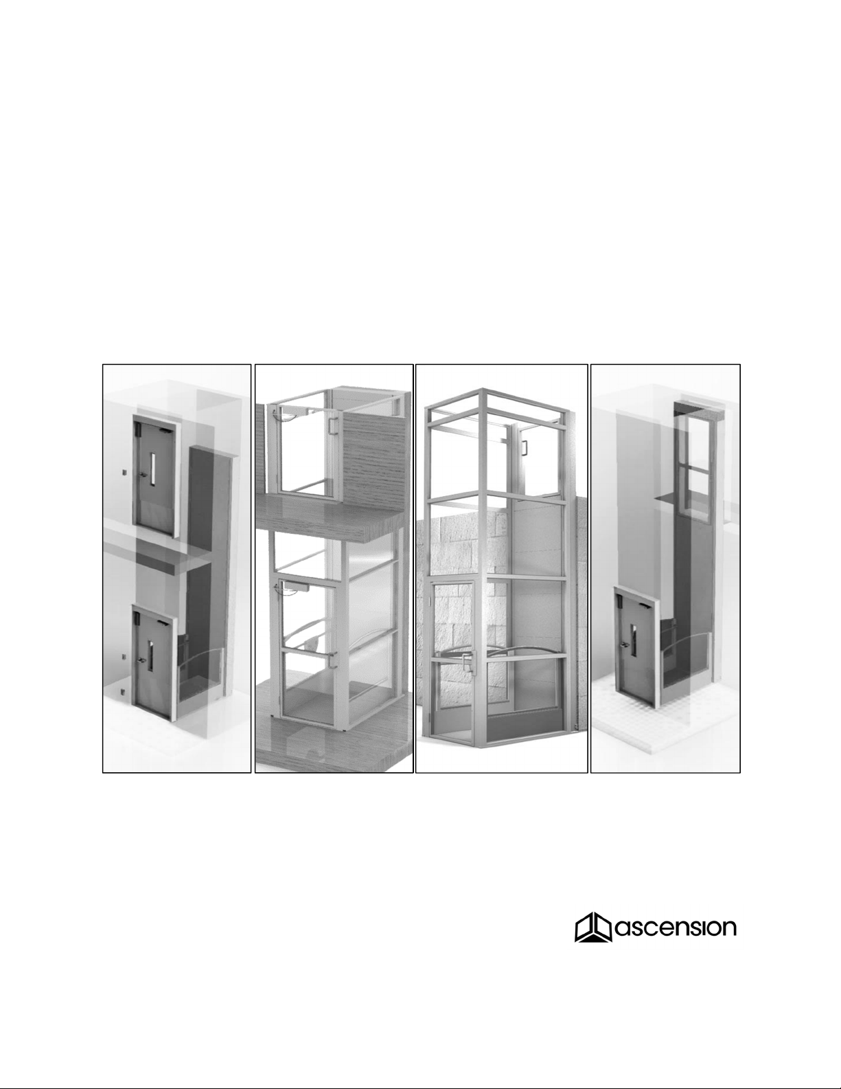
Same-Side,
Shaftway
Same-Side,
Enclosed
Straight-Through,
Enclosed
Straight-Through,
Shaftway
For patent information, see ascension-lift.com/patents
By Philip Brobeck at 8:41 am, Jul 16, 2021

Copyright © 2021 Ascension, a Division of AGM, Tucson, Arizona
http://ascension-lift.com
This document, or parts thereof, may not be reproduced in any form, by any method, for
any purpose, without written permission from Ascension.
ASCENSION CLARITY
WHEELCHAIR LIFT
16C/D/E/S MODEL SERIES
PRODUCT MANUAL
16C
16D
16E
16S
Same-Side,
Shaftway
Same-Side,
Enclosed
Straight-Through,
Enclosed
Straight-Through,
Shaftway
For patent information, see ascension-lift.com/patents

TABLE OF CONTENTS
SECTION 1GENERAL.................................................................................................. 7
1.1Product information ......................................................................................... 7
1.2Definitions ....................................................................................................... 8
1.3Important safety information............................................................................ 9
SECTION 2OPERATION............................................................................................ 10
2.1Description of operation ................................................................................ 10
2.2Standard operation........................................................................................ 11
2.3Manual lowering ............................................................................................ 12
2.4Manually unlocking doors.............................................................................. 13
2.5Using the service override controls ............................................................... 13
SECTION 3BASIC MAINTENANCE AND TROUBLESHOOTING.............................. 14
3.1Routine maintenance .................................................................................... 14
3.2Basic troubleshooting.................................................................................... 14
SECTION 4ADVANCED TROUBLESHOOTING........................................................ 15
4.1Advanced troubleshooting............................................................................. 15
SECTION 5MECHANICAL DISASSEMBLY AND REPAIR ........................................ 16
5.1Safety procedures ......................................................................................... 16
5.2Removing the fascia panels .......................................................................... 17
5.3Removing the upper covers (16E, 16S) ........................................................ 18
5.4Mechanically blocking the platform ............................................................... 19
5.5Hydraulic drive system .................................................................................. 20
5.6Platform safeties ........................................................................................... 22
5.7Slack chain switches ..................................................................................... 23

5.8Lower terminal switch.................................................................................... 24
5.9Upper terminal switch and creep switch........................................................ 25
5.10Door lock switches ........................................................................................ 26
5.11Traveling cable.............................................................................................. 27
5.12Platform operating station ............................................................................. 28
5.13Windows........................................................................................................ 28
5.14Disassembling and detaching the platform.................................................... 31
5.15Runway enclosure (16E, 16D) ...................................................................... 33
SECTION 6ELECTRICAL TESTING AND ADJUSTMENT......................................... 35
6.1Access to the lift controller ............................................................................ 35
6.2Controller diagnostic lights ............................................................................ 36
6.3Removing the controller subpanel................................................................. 39
6.4Testing the switches...................................................................................... 39
6.5Testing supply of power to lift and motor....................................................... 39
6.6Testing the power supply .............................................................................. 40
6.7Testing the batteries...................................................................................... 40
6.8Testing the controller fuse ............................................................................. 41
6.9Testing the motor fuse .................................................................................. 41
6.10Testing the SSR (motor relay)....................................................................... 42
6.11Adjusting alarm volume................................................................................. 43
6.12Two-way communication system .................................................................. 43
6.13Adjusting the illumination .............................................................................. 44
6.14Adjusting/testing the optional power door operators ..................................... 45
6.15Electrical diagram.......................................................................................... 46

SECTION 7INSPECTIONS ........................................................................................ 49
7.1System specifications.................................................................................... 49
7.2Test platform safeties.................................................................................... 49

CLARITY 16C/D/E/S Product Manual SECTION 1
7 117020 Rev C
SECTION 1 General
1.1 Product information
Operational ratings
OCCUPANCY: 1 person
RATED LOAD: 750 pounds (340kg)
AVERAGE SPEED: 20 feet per minute (0.1 m/s)
DUTY CYCLE: 15 minutes of operation per hour repetitive use
(10 cycles for 168” lifting height)
22 minutes maximum single runtime
(15 cycles for 168” lifting height, followed by full cool-down)
Physical ratings
PLATFORM SIZE: 36" wide x 56" long, 42” minimum side height
MATERIALS: Platform, base frame, lifting device: Mild steel
Accent rails and grab bar: Stainless steel
Guide rails and enclosure framing: Aluminum alloy
Windows: High impact strength clear thermoplastic
FINISH: Oven-baked powder coat
Brushed stainless
ELECTRICAL: Input power: 120VAC, 60Hz, 6A, single phase
Motor: 24VDC, 3hp (2.1kW)
Batteries: 2X 12VDC 35A-h AGM SLA batteries
Duracell® Ultra DURA12-35C
Control circuits: 24VDC

CLARITY 16C/D/E/S Product Manual SECTION 1
8 117020 Rev C
1.2 Definitions
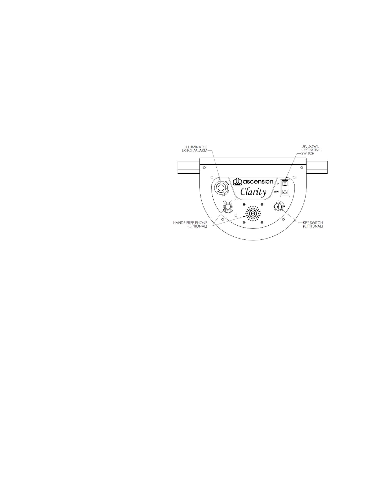
Emergency stop switch The red pushbutton provided at the platform operating
station. Pushing this button immediately stops the lift until it is manually reset.
Fascia The smooth surface extending from the upper landing sill to the level of the
lower landing.
Fascia panel One of the sheet metal covers used to enclose the machinery cabinet
and form the fascia.
Guide rails The vertical tracks that the platform travels on and form the sides of the
machinery cabinet.
Lower landing The lower-elevation level that the lift serves.
Lower landing door The door providing access to the platform from the lower landing.
Machinery cabinet The enclosed space in which the lifting and control mechanisms
are located. The machinery cabinet forms the rear wall of the runway and extends
from the lower landing to the upper landing.
Operating stations The controls for raising and lowering the platform. The operating
station inside the platform has an emergency stop switch. The operating stations
outside the platform may be mounted remotely.
Operating switch An up/down rocker switch used to raise/lower the platform.
Platform The traveling cab that carries a passenger between levels.
Platform brackets The weldments extending from the machinery cabinet that the
platform mounts to.
Runway The vertical space through which the platform moves as it travels between
landings.
Runway enclosure The walls or barriers that surround the runway, restricting access
to the inside of the runway.
Upper landing The higher-elevation level that the lift serves.
Upper landing door The door providing access to the platform from the upper landing.

CLARITY 16C/D/E/S Product Manual SECTION 1
9 117020 Rev C
Figure 1: Parts identification
1.3 Important safety information
When using the lift, the following basic safety precautions and practices must be
observed:
1. Read and understand all of the information contained in this manual.
2. Do not overload the platform. The lifting capacity is 750 lbs.
3. Operate the lift only as described in Section 2 of this manual.
4. Use the lift for movement of people only.
5. Do not expose any part of the lift to a direct liquid stream or spray, such as a
water hose. This could create an electrical shock or fire hazard.
6. Do not operate the lift in the presence of combustible or explosive gas or fumes.
The electrical components of the lift could cause ignition of these chemicals.

CLARITY 16C/D/E/S Product Manual SECTION 2
10 117020 Rev C
SECTION 2 Operation
2.1 Description of operation
Vertical motion of the platform is controlled by the three (3) operating switches located
in the platform and at the landings. While any switch is in use, the other switches are
disabled. These are constant-pressure type switches, meaning that the platform stops
when the switches are released.
A door at each landing permits passengers to enter and exit the platform. Each door is
equipped with an electric lock that prevents the door from being opened while the
platform is away from the given landing, ensuring the safety of those inside and outside
the platform. Both doors are self-closing.
Two parallel-connected hydraulic cylinders raise and lower the platform. When the "Up"
circuit is energized, an electric motor operates a hydraulic pump which provides
pressurized hydraulic fluid to the cylinders, causing the cylinder rods to extend and raise
the platform. When the "Down" circuit is energized, a hydraulic valve is opened to allow
a controlled, gravity-driven descent. It takes approximately 45 seconds for the platform
to travel in either direction through its maximum travel range of 168 inches (14 feet).
The lift is equipped with standard battery backup that allows the platform to be operated
up and down at least five (5) cycles in the event of a power outage. Additionally, the lift
is equipped with a manual lowering pull handle that can be used to lower the platform in
an emergency. Use of the override pull handle is restricted to authorized personnel
only. The platform will descend at a controlled speed as long as the handle is pulled
until it rests at the lower landing.
The drive unit and electrical controller are located at the base of the machine cabinet,
behind the bottom fascia panel. Equipment at this location includes the motor, pump,
power supply, batteries, controller circuit board, and motor relay.
CLARITY 16C/D/E/S Product Manual SECTION 2
11 117020 Rev C
2.2 Standard operation
The main power disconnect for the lift must be in the “on” position for the lift to
operate, even on battery power.
Both landing doors must be closed and locked for the platform to operate.
Each landing door unlocks for as long as the platform remains at that landing.
Pressing an operating switch in a valid direction of travel will lock the door.
Move the platform using any of
the three (3) operating switches.
The operating switches must be
held with constant pressure until
the platform stops at the upper or
lower landing. Releasing the
switch will stop the platform.
Push the emergency stop button
to immediately prevent any
up/down motion and cause the
audible alarm to sound. Turn clockwise to deactivate and reset the switch.
If included, press the “PUSH FOR HELP” button to call a preprogrammed number.
See Section 6.12 for the communication system configuration information.
By default, the platform lighting will illuminate for at least thirty (30) seconds when
either door is opened or any operating switch is used. Lighting also activates during
an AC power outage. See Section 6.13 for information on adjusting brightness or
mode of operation. See Section 6.11 for adjusting alarm volume.
If the lower landing door is equipped with an automatic operator, press a “down”
operating switch while the platform is present at that landing to open the door. If the
upper landing door is equipped with an automatic operator, press an “up” operating
switch while the platform is present at that landing to open the door. Each operator
will hold the door open for a set time period and then automatically close the door.
Figure 2: Platform operating station

CLARITY 16C/D/E/S Product Manual SECTION 2
12 117020 Rev C
2.3 Manual lowering
The manual lowering pull handle can be used to lower the platform when power is
unavailable. It is operated from upper landing (16E, 16S) or lower landing (16C, 16D).
1. 16E, 16S:
a. Locate pull handle at the upper landing, near the base of the upper landing
door (See Figure 3, 16E/16S). Remove the torx head screw to release
manual lowering pull handle.
b. Push on the near end of the manual lowering pull handle to rock the far end
upward. Pull the handle up and out of the floor plate until you feel tension in
the steel cable attached to the handle.
c. Pull the handle to override the hydraulic lowering valve and lower the
platform. Do not pull with more than 20 pounds of force.
2. 16C, 16D (or any lift equipped with remote manual lowering package):
a. Unlock and open the manual lowering access box (see Figure 3, 16C, 16D).
b. Pull the handle to override the hydraulic lowering valve and lower the
platform. Do not pull with more than 20 pounds of force.
NOTICE
Do not pull handle with more than 20 pounds of force. If the
platform still does not descend, the platform safeties may be
holding the platform in place. Contact a repair technician.
16E, 16S 16C, 16D
Figure 3: Manual lowering
-OR-

CLARITY 16C/D/E/S Product Manual SECTION 2
13 117020 Rev C
2.4 Manually unlocking doors
To manually unlock a locked door, the interlocks locking each door may be manually
overridden. See section 5.10.2.
2.5 Using the service override controls
Certain maintenance and repair tasks require movement of the platform at times when
the safety switches would normally prevent motion. In these circumstances, the service
override controls can be used to bypass the control circuits and directly switch on the
lowering valve or the motor and up valve. The service override controls are an up and
down button on a hand-held pendant to be connected to the lift only when needed.
The service override controls are only intended for use by Ascension dealers and
authorized service companies.
Exercise EXTREME CAUTION while using the service override controls, as they
exist for the express purpose of bypassing the lift’s safety features.
WARNING
CRUSHING AND SHEARING HAZARDS RESULTING IN
SERIOUS INJURY OR DEATH MAY BE PRESENT WHILE
OPERATING THE PLATFORM USING THE SERVICE
OVERRIDE CONTROLS. EXERCISE EXTREME CAUTION.
To use, first remove the bottom fascia panel and electrical box cover as described in
section 5.2, then plug the service override control into the DIN connector on the main
circuit board. Use the buttons on the controller to move the platform up and down.
Using the service override controls will cause the controller circuit board to enter a fault
mode and lock out normal operation. To restore normal operation, reset the controller
using the reset button or the main electrical disconnect switch (see Figure 15 on page
35).

CLARITY 16C/D/E/S Product Manual SECTION 3
14 117020 Rev C
SECTION 3 Basic maintenance and troubleshooting
3.1 Routine maintenance
The owning facility is responsible for the proper maintenance of the lift. The following
checks must be performed every six (6) months:
1. Verify the operation of the lift per Section 2.
2. Verify that the lower platform door interlock engages before the platform moves from
the lower landing. Verify that the upper landing door interlock engages before the
platform moves from the upper landing.
3. Verify that the hydraulic oil in the reservoir (behind the bottom fascia panel at the
base of the machine cabinet) is between the MIN and MAX levels when the platform
is at the lower landing. If the hydraulic oil is low, remove the black reservoir cap and
use a funnel and rubber hose to add more fluid. For indoor lifts use ISO 32 grade
hydraulic oil such as Texaco Rando HD32 or 76 Unax AW32 filtered to 10 microns.
For outdoor lifts use ISO 22 grade low-temperature hydraulic oil.
3.2 Basic troubleshooting
If the lift will not operate, confirm the following before calling a service technician:
Both doors are fully closed.
The key switch (if present) on the operating station in use is in the ON position.
The emergency stop button is not actuated.
The main power disconnect switch is in the ON position.
The branch circuit supplying the lift does not have a tripped breaker or blown fuse.
If these conditions are satisfied but the lift does not operate, contact an authorized
service technician (usually the company that installed the lift). Advanced troubleshooting
to be performed by the technician can be found in Section 4.

CLARITY 16C/D/E/S Product Manual SECTION 4
15 117020 Rev C
SECTION 4 Advanced troubleshooting
4.1 Advanced troubleshooting
Troubleshooting in this section is to be performed by a licensed service technician. See
Section 3.2 for basic troubleshooting before contacting a licensed service technician.
Problem Possible Cause Remed
y
Section Pa
g
e
Platform will not
raise or lower
Hydraulic shutoff valve
is closed
Open shutoff valve 5.1.2 16
Lift controller is in fault
mode
Reset lift controller 6.2 36
Slack chain switches
have been actuated
Restore tension and
reset switches
5.7 23
Disconnected wire Check lift controller
li
g
hts and reconnect
6.2 36
Component failure Electrical testing –
possible component
replacement
6.0 35
Motor does not
run & platform
does not raise
Batteries are
disconnected, dead,
and/or not char
g
in
g
Reconnect red battery
connectors or replace
batteries
5.1.1
6.7
16
40
Motor runs but
platform does
not raise
Shutoff valve is closed Open shutoff valve 5.1.2 16
Low fluid level Fill reservoi
r
3.1 14
Up valve not activating Electrical testing –
possible component
replacement
5.5.1 20
Platform does
not stop level
with landing
Cylinder stop collar set
too low
(
lower landin
g)
Adjust cylinder stop
colla
r
5.5.2 20
Terminal switch
actuating early/late
(
either landin
g)
Adjust terminal switch
actuator
5.8
5.9
24
25
Landing door
will not open
Lower/upper terminal
switch not actuating
Adjust terminal switch
actuator or cylinder stop
5.8/5.9
5.5.2
24
25
20
Disconnected interlock
or terminal switch wire,
or component failure
Electrical testing –
possible component
replacement
5.10
6.2
26
36
Landing door
will not lock
Interlock manually
overridden
Un-override interlock 5.10 26

CLARITY 16C/D/E/S Product Manual SECTION 5
16 117020 Rev C
SECTION 5 Mechanical disassembly and repair
5.1 Safety procedures
The repairs in this section are to be performed by a skilled technician who has
experience working on electromechanical systems and is well versed in standard
industrial safety practices and procedures. In the United States of America, electrical
safety procedures are established in OSHA’s Lockout/Tagout – Hazardous Energy
Sources Standard (29 CFR 1920.147).
Familiarity with the setup and operation of the lift described in previous sections of this
manual is required to effectively perform the repairs listed in this section.
5.1.1 Electrically isolating the lift
To electrically isolate the lift, turn the manual disconnect installed with the lift to the OFF
position. This will completely isolate the lift from AC power and disconnect the logic
controller from DC power from the built-in backup batteries, eliminating the possibility of
unexpected platform movement.
While servicing the lift, be aware that some parts will remain live at 24VDC due to
connection to the batteries. To isolate the batteries, open the machinery cabinet and
disconnect the red battery connectors located just above the left battery.
5.1.2 Hydraulically isolating the pumping unit
A shutoff valve is provided to isolate the hydraulic power unit from the lifting cylinders. It
is located just to the left of the electrical box in the base of the machine cabinet, just
above the motor and pumping unit. Close this valve during servicing to prevent
unintended motion of the platform.
To close the shutoff valve and isolate the pump from the cylinders, turn the handle
horizontal, perpendicular to the tubes connected to the body of the valve. While the
shutoff valve is closed, the pump and lowering valve cannot move the platform.

CLARITY 16C/D/E/S Product Manual SECTION 5
17 117020 Rev C
5.2 Removing the fascia panels
Most of the functional components inside the machinery cabinet can be accessed by
removing the bottom fascia panel while the platform rests at the lower landing.
WARNING
CRUSHING AND SHEARING HAZARDS EXIST WHILE
OPERATING THE PLATFORM WITH ONE OR MORE FASCIA
PANELS REMOVED. EXERCISE EXTREME CAUTION.
1. Remove the two (2) screws just above the platform floor fastening the bottom fascia
cover. Set the cover aside.
2. Remove the four (4) screws near the top of the bottom fascia panel.
3. Slide the fascia panel up to remove it, taking care not to scratch the other panels.
4. Remove additional panels in the same manner.
5. To reinstall panels, perform the above steps in reverse order. Install screws with a
manual screwdriver, finding the existing threads by feel.
NOTICE Reinstalling fascia panel screws with a power driver is likely
to damage the threads and result in loose fixing.
CLARITY 16C/D/E/S Product Manual SECTION 5
18 117020 Rev C
5.3 Removing the upper covers (16E, 16S)
The upper covers form the insides of the side posts at the upper landing and support
the upper door and strike. Removal of these covers grants access to the upper terminal
switch, creep switch, and upper door interlock switch.
WARNING FALLING HAZARD WHEN UPPER DOOR IS REMOVED AND
PLATFORM IS NOT AT UPPER LANDING.
CAUTION PINCHING HAZARD WHEN UPPER COVERS ARE
REMOVED. EXERCISE CAUTION.
1. Raise the platform to the upper landing to prevent falling when the upper door is
removed. Otherwise, use fall protection and restrict access to the area.
2. Manually unlock the door per the instructions in section 5.10.2.
3. Remove the hinge-side upper cover (with door attached) by removing two (2) screws
fastening it to the top of the side rail, all screws fastening it to the vertical face of the
side rail, and three (3) screws attaching it to the landing plate at the bottom.
4. Unfasten the strike-side upper cover (with door interlock switch attached) in the
same manner as the hinge-side cover. However, the strike-side upper cover is fixed
at the bottom with only two (2) screws.
5. Lift the strike-side upper cover up several inches to expose the cord from the upper
door interlock switch. Disengage the cord from the U-shaped slot in the landing
plate and pull it up another several inches to find the connectors labeled “P5.”
Disconnect the connectors and take precautions to prevent the lower wiring harness
from falling down into the machine cabinet. If present, also disconnect the
connectors from the back of the operating station mounted over the skin.
6. After servicing, reassemble by performing the steps above in reverse order. Take
care not to pinch the cable from the upper door interlock switch during installation; it
must be routed through the “hole” formed by the opposing U-shaped cutouts in the
landing plate and upper strike-side cover.
CLARITY 16C/D/E/S Product Manual SECTION 5
19 117020 Rev C
5.4 Mechanically blocking the platform
Most repairs on the Clarity lift can be accomplished with the platform resting at the lower
landing. Ascension recommends against working under the raised platform unless it is
necessary to do so. Any time work will be performed under the platform, it must first be
blocked. Never place a load on the platform while it is supported by mechanical
blocks.
WARNING RISK OF CRUSHING. DO NOT PLACE ANY LOAD ON THE
PLATFORM WHILE IT IS BLOCKED FOR SERVICE.
Provision and use of blocking means is the responsibility of the servicing company.
Blocking means must be stable and capable of supporting 450 lb. (200 kg).

CLARITY 16C/D/E/S Product Manual SECTION 5
20 117020 Rev C
5.5 Hydraulic drive system
5.5.1 Description
The hydraulic system includes the hydraulic power unit, two (2) lifting cylinders, a
shutoff valve, and the tubing connecting the components. The hydraulic power unit
includes an integrated motor, pump, reservoir, and manifold with two solenoid valves:
Lowering valve: When the solenoid is energized, the valve opens and allows fluid to
flow out of the cylinders and back to the reservoir, lowering the platform by gravity.
Up valve: When the solenoid is energized, the valve closes to direct fluid to the
cylinders. When the valve is in its normally open state, fluid bypasses from the
pump directly back to the reservoir. This valve prevents the platform from coasting
above the upper landing and provides redundant safety with the motor relay.
To raise the platform, the motor and up valve are energized to pump fluid from the
reservoir through a tee to the parallel-connected cylinders. As the cylinders extend,
they raise the platform at double speed by means of a 2:1 chain suspension system.
As each cylinder extends, fluid stored in the rod end flows out the top port and refills the
reservoir. As gravity lowers the platform by retracting the cylinders, it creates a vacuum
in the rod end of the cylinder that draws fluid back into the empty volume, acting as
additional reservoir capacity.
5.5.2 Cylinder stop collars
A shaft collar installed at the top of each cylinder rod acts as a lower physical stop and
prevents the rod from retracting too far once the platform reaches the lower landing.
The stop collars should not normally need adjustment after initial installation of the lift. If
adjustment is necessary, loosen the screw on each collar then use the manual lowering
pull handle to lower the platform to where it rests on the ground without any slack in the
lifting chains. Slide each collar down until it contacts the top of the cylinder barrel and
tighten the screw to lock the location.
This manual suits for next models
3
Table of contents
Other Ascension Lifting System manuals


Popular Lifting System manuals by other brands

Ravaglioli
Ravaglioli KPN235WEK manual

SHARKS
SHARKS SH1088 Instruction for operation and maintenance

Lehner Lifttechnik
Lehner Lifttechnik SIGMA user manual

Vestil
Vestil CART-CTD Operation and maintenance manual

AAQ
AAQ AutoLift 163027 Installation manual & operation instructions

Borum
Borum B900TJL owner's manual

Yale Lift-Tech
Yale Lift-Tech 115325 Operation, service & parts manual

Bosch
Bosch VLE 21 Series Repair instructions

WITTUR
WITTUR WSG09 Operating and maintenance manual

ReadyLift
ReadyLift 67-2500CB quick start guide

Anthony Liftgates
Anthony Liftgates ETU-20-44 parts book

Mopedia
Mopedia RI840 instruction manual


