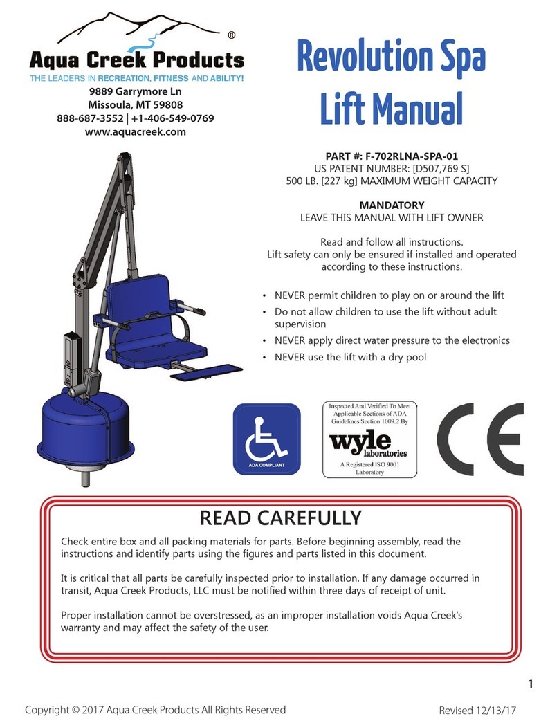
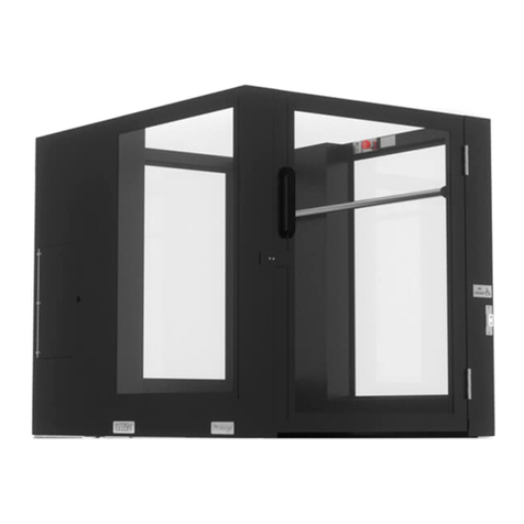
Ascension 5442P User manual

OPERATING MANUAL
ASCENSION MAESTRO
PORTABLE WHEELCHAIR LIFT
MODEL 2040T
OPERATING MANUAL
ASCENSION PROTEGE
PORTABLE WHEELCHAIR LIFT
MODEL 5442P
Patented – see www.ascension-lift.com/patents
By Philip Brobeck at 5:31 pm, Dec 20, 2018


OPERATING MANUAL
ASCENSION PROTEGE
PORTABLE WHEELCHAIR LIFT
MODEL 5442P

Copyright © 2018 Ascension, a Division of AGM, Tucson, Arizona
This document, or parts thereof, may not be reproduced in any form, by any method, for
any purpose, without the written permission of Ascension.

TABLE OF CONTENTS
INTRODUCTION ............................................................................................................. 1
About This Manual ....................................................................................................... 1
Additional Information .................................................................................................. 2
Getting Help ................................................................................................................. 2
Contacting Ascension .................................................................................................. 3
SECTION 1 ..................................................................................................................... 4
Product Information ..................................................................................................... 4
Terminology ................................................................................................................. 5
Important Safety Information ....................................................................................... 6
Description of Operation .............................................................................................. 7
SECTION 2 ..................................................................................................................... 9
Setup Instructions ........................................................................................................ 9
SECTION 3 ................................................................................................................... 13
Operation ................................................................................................................... 13
SECTION 4 ................................................................................................................... 14
Installing the Casters for Portability ........................................................................... 14
Operating the Lift Without Power ............................................................................... 16
Manual Transportation ............................................................................................... 17
Forklift Transportation ................................................................................................ 17
Storage ...................................................................................................................... 18
Outdoor Use .............................................................................................................. 18
Extension Cord Use ................................................................................................... 18
SECTION 5 ................................................................................................................... 19
Troubleshooting ......................................................................................................... 19


Operating Manual Introduction
PROTEGE 5442P
1 112509 Rev G
INTRODUCTION
The Americans with Disabilities Act (ADA) of 1990 established the legal requirement for
public facilities to provide access and reasonable accommodations for people with
disabilities. In response to this requirement, the Ascension PROTEGE portable
wheelchair lift provides the means for individuals who cannot negotiate stairs to gain
access to a moderate vertical floor elevation change, such as a stage, riser, or platform.
This portable wheelchair lift has been designed with both the passenger and the facility
in mind. It provides the passenger with safe access to a stage, and gives the facility
maximum flexibility and ease of use. Because it is transportable, the lift can be quickly
set up for use when needed or put into storage when not needed. The lift can be used
at almost any stage or platform up to 42 inches [1060 mm] high.
About This Manual
This manual provides facility personnel with all the necessary information to safely and
correctly set up, break down, and transport the lift. In the interest of safety, it is
essential that all personnel performing these tasks read and understand this manual.
Section 1 presents operational and physical information, and describes the basic
components and operation of the lift. Section 1 also covers important safety
information.
Section 2 describes the correct set up of the lift for operation.
Section 3 provides the necessary information for safe operation of the lift.
Section 4 describes the break down procedures for the lift and gives recommendations
for transportation.
Section 5 provides basic troubleshooting information in the event that the lift does not
operate correctly.

Operating Manual Introduction
PROTEGE 5442P
2 112509 Rev G
Additional Information
The following sources of information supplement this manual:
Maintenance and Repair Manual A comprehensive Maintenance and Repair Manual
is supplied with each lift. It contains component replacement instructions, as well as
detailed procedures to disassemble, test, and reassemble major components.
Setup and Operation Video A short video on setup and operation can be found at the
following web address: https://ascension-lift.com/lift-setup/.
Getting Help
If you have a question or problem with the lift, review the troubleshooting guide in
Section 5 of this manual, as well as the comprehensive troubleshooting guide in the
Maintenance & Repair Manual. If you are unable to resolve the problem, please contact
Ascension as indicated on the following page, making sure that you have the serial
number of your lift ready. The serial number can be found on the data plate located
inside the platform on the upper right rail. Also, it is recommended that you contact
Ascension while in the immediate vicinity of your lift, as this will reduce the time required
to properly diagnose the problem.

Operating Manual Introduction
PROTEGE 5442P
3 112509 Rev G
Contacting Ascension
Ascension's business hours are 8 a.m. to 5 p.m. Mountain Standard Time, Monday
through Friday.
Telephone: 800-459-0400 Mailing Address: Ascension
Fax: 520-881-4983 Customer Service
Email: sales@ascension-lift.com PO Box 40020
Website: www.ascension-lift.com Tucson, AZ 85717-0020

Operating Manual SECTION 1
PROTEGE 5442P
4 112509 Rev G
SECTION 1
Product Information
Operational
VERTICAL TRAVEL DISTANCE: 4" to 42" [100mm to 1060 mm], infinitely adjustable
OCCUPANCY: 1 person
MAXIMUM PASSENGER LOAD: 900 pounds [408 kg].
AVERAGE SPEED: 5 feet per minute [25 mm/s].
Physical
DIMENSIONS: 48" wide x 49" high x 61" long [1220 x 1250 x 1550 mm]
WEIGHT: 850 pounds [385 kg]
MATERIALS: Platform, base frame, gates: Mild steel
Platform sheet metal, safety pans: Aluminum alloy
Windows: High impact strength clear thermoplastic
FINISH: Platform: Powder coat
Lift base: Galvanized steel
ELECTRICAL: 120† VAC, 60 Hz, Single Phase, 13 Amps
† Electrical ratings may differ on lifts outside the USA. Check lift data plate for electrical ratings.

Operating Manual SECTION 1
PROTEGE 5442P
5 112509 Rev G
Terminology
To get the maximum benefit from this manual, you should be familiar with the following
terms. Refer to Figure 1 as necessary.
Dock Plate The plate that bridges the gap between the platform floor and the upper
landing surface when the platform is at the upper landing.
Lower Landing Gate The gate that serves the lower landing, or ground level.
Machinery Cabinet The enclosures in which the lifting and control mechanisms are
located. There is one cabinet on each side of the lift. The contents of the machinery
cabinets are accessible through the access panels.
Operating Stations The controls for raising and lowering the platform. All three
operating stations are located on the right side of the platform. The operating station
inside the platform has an emergency stop switch.
Platform The compartment in which the passenger rides.
Upper Landing The stage, platform, or riser that the lift serves.
Upper Landing Gate The gate that serves the upper landing, or stage.
Figure 1

Operating Manual SECTION 1
PROTEGE 5442P
6 112509 Rev G
Important Safety Information
When using the lift, the following basic safety precautions and practices must be
observed:
1. Read and understand all of the information contained in this manual.
2. Do not expose any part of the lift to a direct liquid stream or spray, such as a water
hose. This could create an electrical shock or fire hazard.
3. Do not operate the lift in the presence of combustible or explosive gas or fumes.
The electrical components of the lift could cause ignition of these chemicals.
4. Do not operate the lift if the electrical cord has become frayed or if its outer
insulation has been removed, as this could create an electrical shock or fire hazard.
5. Do not allow any equipment, including the lift itself, to lie across or on the electrical
cord, as this could cause the cord to become damaged, resulting in electrical shock
or fire hazard.
6. Set up the lift for operation only in accordance with the instructions in Section 2 of
this manual. If the lift cannot be set up as described, contact the manufacturer to
determine the correct set up for a particular application.
7. The upper height limit sensor adjustment must be confirmed every time the lift is
relocated. Failure to do so could result in serious injury to the user.
8. Operate the lift only as described in Section 3 of this manual.
9. Use extreme caution when moving the lift on an incline, as the lift weighs
approximately 850 pounds [385 kg].
10. Transport the lift as described in Section 4 of this manual.
11. Use the lift for movement of people only.
12. Use an extension cord only as described in Section 4 of this manual.
13. Always close and lock all access panels and remove all keys before leaving the lift
unattended.
14. Never leave the lift unattended while setting the lift up for operation or installing the
casters for transport.

Operating Manual SECTION 1
PROTEGE 5442P
7 112509 Rev G
Description of Operation
Two hydraulic cylinders raise and lower the platform. When the "Up" circuit is
energized, an electric motor operates a hydraulic pump which provides pressurized
hydraulic fluid to the cylinders, causing the cylinder rods to extend and raise the
platform. When the "Down" circuit is energized, a hydraulic valve is shifted so that the
fluid flows in the opposite direction through the hydraulic circuit and the platform is
lowered.
A gate at each end of the lift permits passengers to enter and leave the platform. The
lower landing gate will open only when the platform is lowered all the way. The upper
landing gate can be fully opened only when the platform is at the upper landing. Both
gates are self-closing.
The height limit sensor is located in the left-hand machinery cabinet. This switch halts
the movement of the platform when it reaches the upper landing, and its adjustment
must be confirmed every time the lift is relocated.
The motion of the platform is controlled by any of the three operating switches located
on the right side of the lift. These are constant-pressure type switches, so that when a
switch is released the platform stops. It takes approximately 40 seconds for the
platform to move through its full range of 42 inches. These switches are interlocked so
that while one switch is activated, pressing another switch in the opposite direction will
not cause the lift to stop; the original action will continue.
The lift is equipped with an under-platform safety pan that will halt all motion of the
platform if it encounters an obstruction as it descends. If this occurs, use the hand pump
or setup key to raise the platform and allow for the removal of the obstruction. The
under-platform safety pan completely covers the bottom and side edges of the platform.

Operating Manual SECTION 1
PROTEGE 5442P
8 112509 Rev G
The dock plate is tethered to the bottom of the upper landing gate by a cable that lowers
the dock plate as the gate opens. When the upper landing gate is closed, the dock
plate is raised by its tether.
The unit is equipped with a hand pump that can be used to raise or lower the platform in
an emergency, or when the casters are being put under the platform and power is not
available. The hand pump is located in the right-hand machinery cabinet.
The casters are stored in the left-hand machinery cabinet. They can quickly and easily
be installed underneath the lift so that the lift can be moved to another location. The
hydraulic system is used to raise and lower the platform and base frame when installing
or removing the casters.
The electrical control panel is located inside the right-hand machinery cabinet. This
panel includes the power supply, control system relay, and main power relay. A Ground
Fault Circuit Interrupter (GFCI) and lockable disconnect switch with integrated overload
protection are located on the electrical cord near the wall plug.

Operating Manual SECTION 2
PROTEGE 5442P
9 112509 Rev G
SECTION 2
Setup Instructions
1. Prior to operation, position the upper landing end of the lift 1 to 3 inches [25 to 75
mm] from and approximately parallel to the edge of the upper landing (stage). This
space should be flat, level, and free of any debris or obstructions (including the lift’s
power cord).
2. Plug the power cord into a grounded electrical outlet and turn the disconnect switch
to the ON position. Raise the platform at least 12 inches [305 mm]. To do so, turn
the barrel key in the setup switch on the front of the lift and hold an operating switch
‘up’, OR use the manual pump per Section 4, Operating the Lift Without Power.
Certain option packages (incl. universal key switches) require manual operation.
3. Remove all four casters from the platform underside by pulling them straight down.
Place them in the caster storage brackets in the left-hand machinery cabinet
according to their color codes. See Figure 2. The casters must be removed before
the lift can be operated.
Figure 2

Operating Manual SECTION 2
PROTEGE 5442P
10 112509 Rev G
4. Use an operating switch to lower the platform to the floor.
5. Enter the platform and use the operating switch located inside the platform to move
the platform upward until it stops.
6. Open the inner access panel on the left-hand machinery cabinet and remove the
height adjustment tool from its storage bracket. Refer to Figure 2 for identification of
the adjustment tool.
7. Use the adjustment tool to remove the magnetic optical reflector from the vertical
guide rail. To do so, place the adjustment tool on the reflector, turn it clockwise a
quarter turn to engage the reflector, and then pull the reflector off the guide rail.
Reserve the reflector in the adjustment tool until Step 11. The reflector is located
near the bottom of the cabinet and is marked by a yellow decal. See Figure 3.
8. Use an operating switch to move the platform so the platform floor is approximately
level with the upper landing.
Figure 3

Operating Manual SECTION 2
PROTEGE 5442P
11 112509 Rev G
9. Open the upper landing gate completely. Verify that the dock plate rests securely on
the upper landing, and provides a smooth, level, and safe transition to and from the
platform. See Figure 4.
Figure 4
10. If the platform is not at the correct height, repeat Steps 8 & 9 until it is correct.
11. With the platform at the correct height, use the height adjustment tool to reattach the
reflector to the vertical guide rail. Rest the adjustment tool in the u-shaped bracket
marked by the yellow decal then slide it forward until the magnet on the reflector
engages the vertical guide rail. See Figure 5. Twist the adjustment tool a quarter turn
counterclockwise to disengage it from the reflector after it is placed. You should see
a red dot at the bottom edge of the reflector.

Operating Manual SECTION 2
PROTEGE 5442P
12 112509 Rev G
Figure 5
12. Lower the platform several inches and then raise it again until it stops automatically.
Repeat Step 9 to verify that the height is correct. Re-position the optical reflector if
necessary until the platform stops at the correct height.
13. Return the height adjustment tool to the tool holder in the left-hand machinery
cabinet.
14. The lift is ready for use.
WARNING!
The lift’s stop height MUST be verified every time the lift is relocated, and reset
if necessary. Failure to do so could result in serious injury to the user.
WARNING!
Always close and lock all access panels and remove all keys before leaving
the lift unattended.

Operating Manual SECTION 3
PROTEGE 5442P
13 112509 Rev G
SECTION 3
Operation
The disconnect switch in the lift cord must be set to ‘ON’ for the lift to operate.
The casters must be removed for the lift to operate. See Section 2.
The On/Off switch in right machinery cabinet must be set to ‘ON’ for lift to operate.
This switch may be set to ‘OFF’ to disable the lift.
Both gates must be closed for the lift to operate.
Move the platform by using any one of the three operating switches. The operating
switches must be held with constant pressure until the platform stops at the upper or
lower landing.
Push the emergency stop button to activate it. Reset the button to allow operation.
If the platform is at the lower landing and the lower landing gate interlock prevents
the gate from being opened, hold an operating switch "Down" to disengage the
interlock.
The under-platform safety pan will halt the platform if it encounters an obstruction as
it descends. If this occurs, remove the obstruction to resume motion. The lift may be
raised using the hand pump or the setup key if necessary.

Operating Manual SECTION 4
PROTEGE 5442P
14 112509 Rev G
SECTION 4
Installing the Casters for Portability
1. Plug the power cord into a grounded electrical outlet and use an operating switch
to move the platform upward at least 12 inches [305 mm].
2. Remove all four casters from the left-hand machinery cabinet and install them into
the color-coded sockets located at the corners of the platform underside. See
Figure 6 and Figure 7. The rigid casters (marked yellow) must be oriented so the
lift will roll forward and backward. When correctly installed, the casters will not slide
out without being pulled straight down.
Figure 6
WARNING!
Always close and lock all access panels and remove all keys before leaving
the lift unattended.
WARNING!
Never leave the lift unattended while performing the following procedures.
Other manuals for 5442P
1
Table of contents
Other Ascension Lifting System manuals
Popular Lifting System manuals by other brands

probst
probst SDH-LIGHT operating instructions

Reechcraft
Reechcraft PowerLift M20C Operators safety manual

Bike-Lift
Bike-Lift CFL-500 Maintenance manual

Ravaglioli
Ravaglioli RAV 1380 manual

Jungheinrich
Jungheinrich AM 30 operating instructions

Ravaglioli
Ravaglioli KPN235WPO Translation of the original instructions

Dhollandia
Dhollandia DH-V Series Operation manual

Linak
Linak DL8 user manual

Atlas Equipment
Atlas Equipment Garage Pro 8000 EXT Installation & operation manual

Lippert Components
Lippert Components Level-Up Installation and owner's manual

Snorkel
Snorkel S2632E Repair parts manual

Faraone
Faraone ELEVAH 65 MOVE Use and maintenance instructions