Ascent Communication Technology ACT EC2400 User manual

ACT EC2400
HD Encoder
User Guide
Revision A

ACT EC2400 4-in-1 MPEG-4 AVC / H.264 HD Encoder
User Manual
ACT Document Number: ACT EC2400 User Manual Revision A
Copyright © 2016 Ascent Communication Technology Limited.
All rights reserved. Reproduction in any manner whatsoever without the express written permission of
Ascent Communication Technology is strictly forbidden.
This document is produced to assist professional and properly trained personnel with installation and
maintenance issues for the product. The capabilities, system requirements and/or compatibility with
third-party products described herein are subject to change without notice.
For more information, contact ACT: sales@ascentcomtec.com
Revision History
Revision
Date
Reason for Change
A
1/18/2016
Initial Release
Solutions Provider for FTTx, RFoG and HFC www.ascentcomtec.com Page 2 of 43

Table of Contents
Chapter 1. Product Introduction ............................................................................................................................................ 4
1.1 Outline········································································································································································ 4
1.2 Main Features··························································································································································· 4
1.3 Specifications···························································································································································· 5
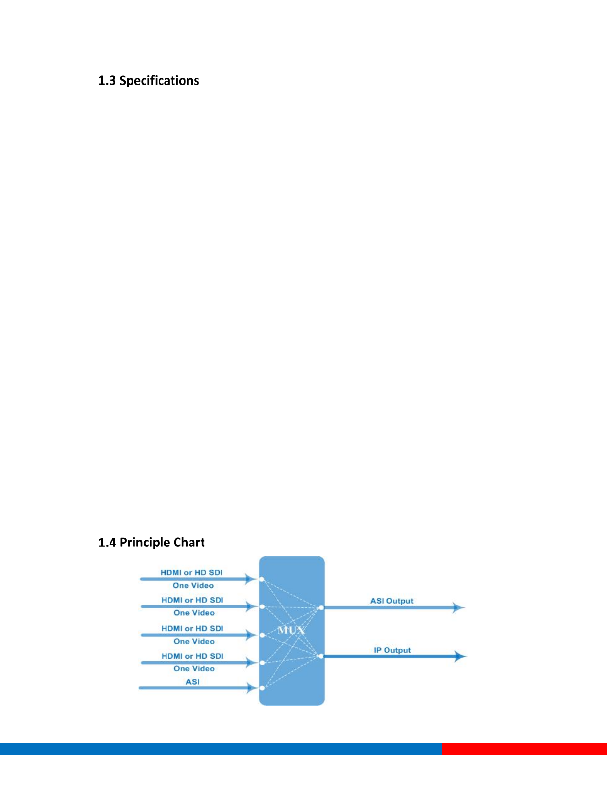
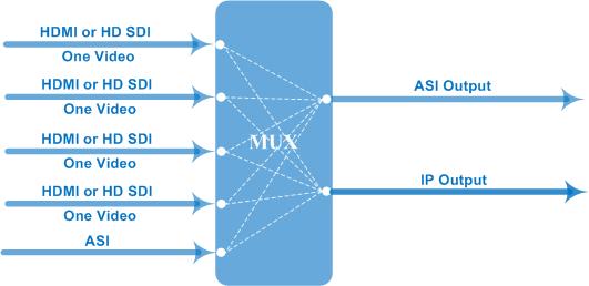
1.4 Principle Chart ·························································································································································· 5
1.5 Appearance and Illustration ···································································································································· 6
Chapter 2. Installation Guide................................................................................................................................................. 8
2.1 Acquisition Check····················································································································································· 8
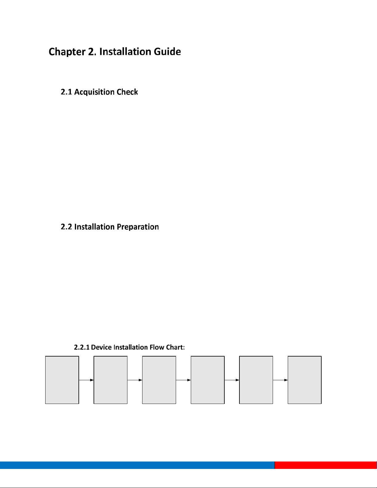
2.2 Installation Preparation············································································································································ 8
2.3 Wire’s Connection ·················································································································································· 10
2.4 Signal Cable Connection······································································································································· 10
Chapter 3. Operation ............................................................................................................................................................ 13
3.1 Initializing································································································································································· 13
3.2 General Settings····················································································································································· 13
Chapter 4. SNMP Operation................................................................................................................................................ 24
4.1 Installation ······························································································································································· 24
4.2 Software Operation ················································································································································ 24
4.3 EC2400 4 in 1 MPEG-4 AVC/ H.264 HD Encoder Operation ·········································································· 30
4.4 Other Settings························································································································································· 39
Chapter 5. Troubleshooting ................................................................................................................................................. 42
Contact Information ............................................................................................................................................................ 43
Solutions Provider for FTTx, RFoG and HFC www.ascentcomtec.com Page 3 of 43

The ASCENT EC2400 4 in 1 MPEG-4 AVC/H.264 HD encoder is a professional HD audio & video encoding
and multiplexing device with powerful functionality. It is equipped with 4 HDMI (or SDI) input channels
allowing for 4 HD programs can be processed simultaneously. It adopts the MPEG-4 AVC/H.264 High
Profile encoding format to guarantee the highest picture quality. The EC2400 has an ASI input and can
multiplex the input TS with the 4 encoded programs to generate a stream output through ASI and IP. In
addition, the PSI/SI information can be inserted into an MPTS output. In conclusion, the EC2400’s highly
integrated and cost-effective design makes the device widely used in varieties of digital distribution
systems.
Supports AVC/H.264 High Profile Level 4.0 video encoding
Supports advanced video pretreatment algorithm
Supports MPEG-1 Layer II, HE-AAC (V2), and LC-AAC audio encoding formats
4 channel HDMI (or SDI) inputs and 1 ASI input with mux
Supports PSI/SI editing and inserting
Supports VBR or VBR video bitrate mode
Supports 720P, 1080I, and 1080P HD video formats
Supports ASI output MPTS or 4 × SPTS
Supports IP output (UDP) MPTS and 4 channel SPTS, unicast/multicast
Supports IP null packet filter
Supports PID filter and transparent transport
Real-time effective output bitrate monitoring
Supports device updates through NMS port
Supports LCD / keyboard operation and network management (SNMP)
Solutions Provider for FTTx, RFoG and HFC www.ascentcomtec.com Page 4 of 43

Input
4 × SDI input
EC2400-SDI
4 × HDMI input
EC2400-HDMI
1 × ASI input, BNC interface
Video
Resolution
1920×1080_59.94P, 1920×1080_50P
1920×1080_59.94i, 1920×1080_50i
1280×720_59.94p, 1280×720_50p
720x576_50i, 720x480_59.94i
Encoding
MPEG-4 AVC/H.264 High Profile Level 4.0
Bitrate
0.8 Mbps ~ 19 Mbps (each channel)
Rate Control
CBR, VBR
GOP Structure
IBBP
Advanced Pretreatment
De-interlacing, noise reduction, sharpening
Audio
Encoding
MPEG-1 Layer II, HE-AAC(V2), LC-AAC
Sampling rate
48 kHz
Resolution
24-bit
Bitrate
64 Kb/s ~ 384 Kb/s each channel
Multiplexing
1 × ASI input multiplexed and 4 encoding channel SPTS
output
2 × ASI outputs, BNC interface
MPTS and 4 SPTS over UDP
10/100Base-T Ethernet interface
Supports unicast / multicast
System
LCD/keyboard operation, net manager (SNMP)
Chinese-English control interface
Ethernet software upgrade
General
Dimensions (W×D×H)
440mm × 410mm × 44.5mm
Approx. weight
4 kg
Temperature range
0 ~ 45°C(operating), -20 ~ 80°C(storage)
Power Requirements
AC 110V±10%, 50/60 Hz
AC 220V±10%, 50/60 Hz
Power consumption
25W
Solutions Provider for FTTx, RFoG and HFC www.ascentcomtec.com Page 5 of 43

Front Panel Illustration:
1 2 3 4 5 6
Indicated area: All indicators will light on when the device is on the current working state.
1
LCD Screen
2
Indicators
Power Indicator
TS in: Input Lock Indicator
CH1 TS out – CH4 TS out: device starts to encode and
output TS
CH1 Alarm – CH4 Alarm: device has stopped encoding
or there is an encoding error
3
UP / DOWN, LEFT / RIGHT Keys
4
Enter Key
5
Menu Key
6
Lock Key
Solutions Provider for FTTx, RFoG and HFC www.ascentcomtec.com Page 6 of 43

Rear Panel 1
1 2 3 4 5 6 7
Rear Panel Illustration (EC2400-SDI):
1 2 3 4 5 6 7
1
4 × HDMI Input Ports-- EC2400-HDMI
4 × SDI Input Ports-- EC2400-SDI
2 ASI Input Port
3 2 × ASI Output Ports
4 Data Port (for IP Signal Output)
5 NMS (Network Management Port)
6 Power Switch and Socket
7 Grounding Pole
Solutions Provider for FTTx, RFoG and HFC www.ascentcomtec.com Page 7 of 43

Users should check the contents of the package of the device prior to installation to ensure that all
items on the packing list are included. Items contained within the package:
EC2400 4-in-1 MPEG-4 AVC/H.264 HD Encoder
User Manual
4 × HDMI Cable for EC2400-HDMI
4 × SDI Cable for EC2400-SDI
ASI Cable
Power Cord
If any item is missing or different from the list above, please contact your local dealer.
Please follow the below steps to install the device. The details of installation will be described in this
chapter. Users can also refer to the rear panel chart in Chapter 1 during the installation.
The main contents of this chapter include:
Checking the device for possible missing or damaged components
Preparing a suitable environment for installation
Installing the encoder
Connecting signal cables
Connecting communication port (if necessary)
Connecting
Grouding
Wire and
Power
Cord
Acquisition
Check Fixing
Device Setting
Parameter Running
Device
Connecting
Signal Wire
Solutions Provider for FTTx, RFoG and HFC www.ascentcomtec.com Page 8 of 43

Item Requirement
Machine Hall Space When installing the machine frame array into a machine hall, the distance
between 2 rows of machine frames should be 1.2 ~ 1.5 m and the distance
between a machine frame and a wall should be no less than 0.8 m.
Machine Hall Floor Electric Isolation, Dust Free
Volume resistivity of ground anti-static material: 1×10⁷ ~ 1×10¹⁰Ω
Grounding current limiting resistance: 1M (Floor bearing should be greater
than 450 kg/㎡)
Environment
Tempe rature
5 ~ 40
°C
(sustainable), 0 ~ 45°C(temporary)
Installing air-conditioning is recommended
Relative Temperature 20% ~ 80% (sustainable), 10% ~ 90% (temporary)
Pressure 86 ~ 105 kPa
Door & Window Install rubber strips to seal door gaps and dual-level window glasses.
Wall Can be covered with wallpaper or non-bright paint.
Fire Protection Fire alarm system and extinguisher
Power Device power, air conditioning power, and lighting power should all be
independent of each other. Device power requires AC power 220V 50 Hz.
Please check carefully before running.
Good grounding designs are the basis of reliability and stability for these devices. Good
grounding is also the best guarantee against lightning arresting and interference rejection.
All machine frames should be connected by protected copper strips
Coaxial cable outer conductors and isolation layers should maintain proper electrical
conduction with the metal housing of the device.
The grounding conductor should be copper in order to reduce high frequency impedance.
The grounding wire should be as thick and short as possible and avoid circling.
Users should make sure both ends of the grounding wire are good conductors and rust-
resistant.
Users should not use any other device as part of the grounding electric circuit.
The area of conduction between the grounding wire and device’s frame should be no less than
25 mm2.
Connect the device’s grounding rod to the frame’s grounding pole with copper wire.
Solutions Provider for FTTx, RFoG and HFC www.ascentcomtec.com Page 9 of 43

The grounding wire conductive screw is located at the right end of the rear panel, and the power
switch, fuse, and power supply socket are right next to that. The power switch is on the left, the power
supply socket is on the right, and the fuse is between them.
Connecting Power Cord
Insert one end into the power supply socket, and insert the other end to an AC power source.
Connecting Grounding Wire
The grounding resistance should be less than 1Ω.
Caution
Before connecting power cord to EC 2400 4-in-1 MPEG-4 AVC/H.264 HD
Encoder, user should set the power switch to “OFF.”
The signal connections include the input signal cable and the output signal cable. The cables look like
the following:
Solutions Provider for FTTx, RFoG and HFC www.ascentcomtec.com Page 10 of 43

First find the HDMI or SDI interface on the device according to the connector mark described on the
rear panel illustration in section 1.6, and then connect the HDMI or SDI cable (in the accessories). One
end is connected to the head-end equipment and the other end to the encoder’s HDMI or SDI input
port. The encoder’s HDMI or SDI input port and its connection are illustrated as follows:
User can find the ASI output interface on the device according to the connector mark described on the
rear panel illustration in section 1.6, and then connect the ASI cable (in the accessories). One end is
connected to the encoder’s ASI out connector (ASI out1, ASI out2) abd the other end to the TS stream
multiplexer or modulator’s ASI input port. The encoder’s ASI output interface and its connection are
illustrated as follow:
Solutions Provider for FTTx, RFoG and HFC www.ascentcomtec.com Page 11 of 43

Users can find the DATA interface on the device according to the connector mark described on the rear
panel illustration in section 1.6, and then connect the network cable (CAT5). One end of the network
cable is connected to the encoder’s DATA output connector, and the other end to the TS stream
multiplexer IP input port or other device which can handle IP signal inputs. The encoder’s DATA
connection is illustrated as follows:
Users can find the NMS interface on the device according to the connector mark described on the rear
panel illustration in section 1.6, and then connect the network cable (CAT5). One end of the network
cable is connected to the encoder’s NMS connecter, while the other end should be attached to the
computer or PC. The encoder’s NMS connection is illustrated as follows:
Solutions Provider for FTTx, RFoG and HFC www.ascentcomtec.com Page 12 of 43

The EC2400 4 in 1 MPEG-4 AVC/H.264 HD Encoder’s front panel is its user operating interface. Before
operating, users can decide whether to use default settings or to customize the input and output
parameters settings.
Keyboard Function Description:
ENTER: Activates the parameters which need modifications, or confirms changes after modifications
are done.
MENU: Cancels presently entered value, or restores previous settings and returns to the previous
menu.
LEFT/RIGHT: Moves the “►” to choose or set the parameters.
UP/DOWN: Modifies selected parameters or page up/down when no parameter is selected.
LOCK: Locks the screen / cancels the lock state. After pressing the lock key, the system will ask users
whether or not they want to save present settings. If not, the LCD will display the current configuration
state.
At the “Factory Configuration” page, users can press the ENTER key to restore the factory default
configuration.
After powering on the device, it will take a few seconds to initialize the system. The LCD will show the
device name and output real-time bit rate data in the first row, and the 4 channels’ input video
resolution, frame rate, and real-time encoding bit rate in the second row in that order.
4 in 1 Encoder 65.958 Mbps
1 480I 60 08.235M 2 480I 60 08.241M
By pressing the LOCK key, users can enter the main menu and set the input and output parameters in
the following editing interfaces:
►1 Input Setting 2 ASI Setting
3 Output Setting 4 Network Setting
Solutions Provider for FTTx, RFoG and HFC www.ascentcomtec.com Page 13 of 43

►5 Saving Config 6 Loading Config
7 Version (SNMP)8 Language
The option with “►” is the current selection. Users can press the ENTER key to enter the specified
submenu to modify device parameters.
Under this menu, users can enter the corresponding encoding channel to set the relevant audio and
video input parameters, and select programs to multiplex. The LCD will display 4 submenus from
Encoding Channel 1 to Encoding Channel 4. The setting principle is the same for Encoding Channels 1-4,
so this manual only explains the process for one channel. After pressing the ENTER key, the LCD will
display the following page:
►1.1 Encoder 1 1.2 Encoder 2
1.3 Encoder 3 1.4 Encoder 4
After users enter a submenu, they can enter the corresponding interface to modify device parameters.
►1.1.1 Video 1.1.2 Audio
1.1.3 System 1.1.4 PG Muxer
3.2.1.1 Video Settings
►1.1.1.1 Bitrate 1.1.1.2 BitrateMod
1.1.1.3 Profile 1.1.1.4 Level
Bitrate
By pressing the Enter key, users can modify relevant encoding rate parameters (adjustable range:
0.8M ~ 19M), the specific steps are displayed as follows:
1.1.1.1 Bitrate
8.000Mbps
Solutions Provider for FTTx, RFoG and HFC www.ascentcomtec.com Page 14 of 43

Bitrate Mode
User can choose CBR & VBR at this menu. CBR (Constant Bitrate) means that the bitrate will be a
constant value. VBR (Variable Bitrate) means that the bitrate will always change along with the video
scene changing.
Profile
User can select the H.264 profile configuration it this menu. The H.264 High Profile code format and the
Main Profile code format are the available options.
Level
User can select the H.264 level at this menu. The option with brackets is the current choice.
3.2.1.2 Audio Settings
1.1.1.2 BitrateMod 01/01
[CBR] VBR
1.1.1.3 Profile 01/01
[HIGH] MAIN
1.1.1.4 Level 01/03
[1.2]1.3 2.0 2.1
1.1.1.4 Level 02/03
[2.2]3.0 3.1 3.2
1.1.1.4 Level 03/03
[4.0] 4.1 4.2
1.1.2.1 Bit Rate 1.1.2.2 Format
Solutions Provider for FTTx, RFoG and HFC www.ascentcomtec.com Page 15 of 43

Audio Bit Rate Settings
Users can set the input audio bit rate by pressing the ENTER key to enter the main editing interface.
Options are: 64 kbps, 96 kbps, 112 kbps, 128 kbps, 160 kbps, 192 kbps, 224 kbps, 256 kbps, 320 kbps,
and 384 kbps. After modifications have been made, users can press the ENTER key again to put the
modifications into effect.
1.1.2.1 Bit-rate 01/03
64 Kbps 96Kbps 112Kbps [128Kbps]
1.1.2.1 Bit-rate 02/03
160 Kbps 192Kbps 224Kbps [256Kbps]
1.1.2.1 Bit-rate 03/03
320 Kbps 384Kbps
Audio Format Settings
AAC: Advanced Audio Coding
Users can set the input audio format in this interface. The 3 options are MPEG-1 Layer II, LC-AAC, and
HE-AAC. When users enter the main editing menu, the LCD will display the following pages:
1.1.2.2 Format 01/02
[MPEG1-Layer Ⅱ] LC-AAC
1.1.2.2 Format 02/02
[HE-AAC]
Solutions Provider for FTTx, RFoG and HFC www.ascentcomtec.com Page 16 of 43

3.2.1.3 System Settings
Under this interface, users can set the corresponding system parameters. After modifications have been
made, users can press the ENTER key to put the modifications into effect.
Program Number Setting
Users can set the program number by pressing ENTER to enter this submenu.
Video/Audio/PMT/PCR PID Settings
Users can set these parameters by pressing ENTER to enter these submenus. The maximum PID number
cannot exceed 0x1fff.
1.1.3.2 Video PID
0x0101
1.1.3.3 Audio PID
0x0102
1.1.3.4 PMT PID
0x0100
►1.1.3.1 Prog Number 1.1.3.2 Video PID
1.1.3.3 Audio PID 1.1.3.4 PMT PID
►1.1.3.5 PCR PID 1.1.3.6 IP Enable
1.1.3.7 Out Address 1.1.3.8 Out Port
►1.1.3.9 Null PKT
1.1.3.1 Program Number
0x0101
Solutions Provider for FTTx, RFoG and HFC www.ascentcomtec.com Page 17 of 43

1.1.3.5 PCR PID
0x0101
IP Enable
Out Address/Out Port Settings
Users can modify the out address and out port in the below interfaces.
Null Packet
Users can choose YES (filter the null packet) or NO (don’t filter null packet) to decide whether or not to
filter the null packet.
3.2.1.4 Program Mux Settings
Users can decide whether or not to open the multiplexing function of the device.
Channel Mux
Under this interface, users can decide whether or not to multiplex the channel encoding stream. YES
means that the device multiplexes the encoding stream into the MPTS, while NO means that the output
program is SPTS.
1.1.3.6 IP Enable 01/01
YES [NO]
1.1.3.9 Null Packet 01/01
YES [NO]
1.1.3.7 Out Address
224.002.002.002
1.1.3.8 Out Port
1002
Solutions Provider for FTTx, RFoG and HFC www.ascentcomtec.com Page 18 of 43

1.1.4.1 Channel Mux 01/01
[ YES] NO
Users can check the ASI input program amount in this interface. Prog: 006 means the input program is 6
and Out:003 means that 3 of the 6 programs have been multiplexed.
►2.1 Parse ASI Prog
By pressing the enter key in the main editing interface, users can set device output parameters.
3.2.3.1 IP Out Enable
This is a new function of the encoder. Users can decide whether or not to open the IP output function
by pressing the ENTER key in this menu.
►3.1 IP Out Enable 3.2 IP Out Address
3.3 IP Out Port 3.4 Trans Stream ID
►3.5 Output Stream 3.6 ASI Output
3.7 UTC Time Config 3.8 Null PKT
►3.9 TS Package Num
2.1 Parse ASI Prog Prog: 006 Out: 003
►001 HK1 √002 HK2 X
Solutions Provider for FTTx, RFoG and HFC www.ascentcomtec.com Page 19 of 43

►3.1 IP out Enable
[ YES] NO
3.2.3.2 IP Out Address
If users enable the IP output function, then users can set the device IP output address in this interface.
After users press the ENTER key, the operating interface will display the following page:
►3.2 IP Out Address
224.002.002.002
3.2.3.3 IP Out Port
In this menu, users can set the encoder IP output port number by pressing the ENTER key to enter the
main editing interface.
►3.3 IP Out Port
01001
3.2.3.4 Trans Stream ID
Users can set the device TS ID in this interface after pressing the ENTER key to enter the main editing
page.
►3.4 Trans Stream ID
00000
3.2.3.5 Output Stream
Users can modify the output stream bit rate in this interface after pressing the ENTER key to enter the
main editing page.
3.2.3.6 ASI Output
Users can set the ASI output in the interface under this menu. There are 5 options: MPTS and Channels
1-4.
3.5 Output Stream
040.000 Mbps
Solutions Provider for FTTx, RFoG and HFC www.ascentcomtec.com Page 20 of 43
Table of contents
Other Ascent Communication Technology Media Converter manuals