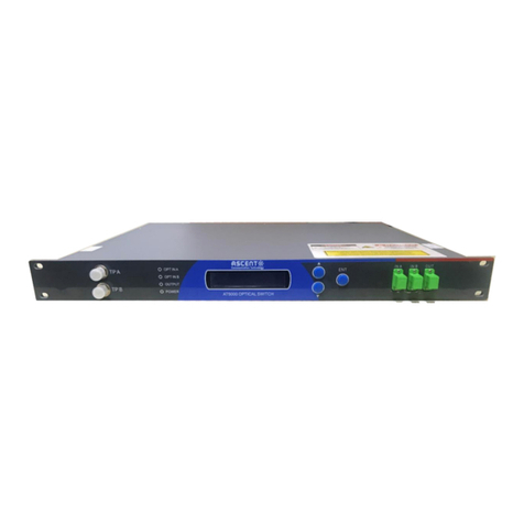
Ascent Communication Technology AE8000 Series User manual

AE8000
INSTALLATION
QuickReference
Guide
RevisionA

ACTAE8000HighDensityCoreSwitchInstallation
QuickReferenceGuide
ACTDocumentNumber:AE8000CORESWITCHQRGRevisionA
Copyright©2011AscentCommunicationTechnologyLimited.
Allrightsreserved.ReproductioninanymannerwhatsoeverwithouttheexpresswrittenpermissionofAscentCommunication
Technologyisstrictlyforbidden.
Thisdocumentisproducedtoassistprofessionalandproperlytrainedpersonnelwithinstallationandmaintenanceissuesfor
theproduct.Thecapabilities,systemrequirementsand/orcompatibilitywiththird‐partyproductsdescribedhereinaresubject
tochangewithoutnotice.
Formoreinformation,contactACT:Sales@ascentcomtec.com
RevisionHistory
RevisionDateReasonforChange
A02/01/2012InitialRelease

Contents
1 Precautions ..........................................................................................................................................4
2 Introduction..........................................................................................................................................5
2.1 Overview.......................................................................................................................................5
2.2 Features........................................................................................................................................5
2.3 Application Diagram....................................................................................................................6
2.4 Specification.................................................................................................................................6
2.5 Models and Options ....................................................................................................................7
3 Installation............................................................................................................................................8
3.1 Equipment Inventory...................................................................................................................8
3.2 Packaging and Transportation...................................................................................................8
3.3 Power and Cooling Requirements.............................................................................................8
3.4 Front View.....................................................................................................................................9
3.5 Side View ....................................................................................................................................10
3.6 Rear View.................................................................................................................................... 11
3.7 Chassis Installation...................................................................................................................12
3.7.1 Cabinet Requirements...........................................................................................................12
3.7.2 Electrical Connections..........................................................................................................12
3.7.3 Air Flow and Cooling System...............................................................................................14
3.8 Card Installation & Removal.....................................................................................................15
3.8.1 General....................................................................................................................................15
3.8.2 Switching & Control Card AE80-SC-[192
│
384]..................................................................15
3.8.3 Line Card AE80-24FE-SFP-2GE............................................................................................17
3.8.4 Line Card AE80-24GE-SFP....................................................................................................18
3.8.5 Line Card AE80-48GE-TX ......................................................................................................19
3.8.6 Line Card AE80-1TE-XFP.......................................................................................................20
3.8.7 Line Card AE80-2TE-XFP.......................................................................................................21
3.8.8 Line Card AE80-4TE-XFP.......................................................................................................22
3.9 Final Checks...............................................................................................................................23
3.10 Switching On..............................................................................................................................23
4 First Time Configuration...................................................................................................................24
5 Basic Interface Commands...............................................................................................................27
5.1 Getting Help................................................................................................................................27
5.2 Command Mode.........................................................................................................................27
5.3 Cancelling a Command.............................................................................................................28
5.4 Saving the Configuration..........................................................................................................28
6 Switching and Routing Features......................................................................................................29
7 Product Warranty...............................................................................................................................30
8 Declaration of Conformity.................................................................................................................31

1Precautions
WARNING!
Thisequipmentisintendedforindoorapplications.Topreventfireorelectricalshock,do
notexposeunitstowaterormoisture.
Ensureadequatecoolingandventilationasspecified.
Theinstallationandoperationmanualshouldbereadandunderstoodbeforeunitsareputintouse.
Alwaysreplaceprotectivecapsonopticalconnectorswhennotinuse.
TypicalconnectorsusedareSC/APC8°green,LC/APC8°green,SC/PCblueorLC/PCblue.
Dangerousvoltagesarepresentwithintheunitatalltimes.Mainspowerkills.
Donotoperateunitwithoutallcoversandpanelsproperlyinstalled.Mainspowerkills.
Cleaning
Useonlyadampclothforcleaningthefrontpanel.Useasoftdryclothtocleantopofunit.Donotusespray
cleanerofanykind.
Overloading
Overloadingwalloutletsandextensioncordscanresultinariskoffireorelectricshock.Useapprovedelectrical
cords.
Damagerequiringservice
UnplugtheunitandreferservicingtoAscentCommunicationTechnologyqualifiedservicepersonnelonly.
Servicing
Donotattempttoservicethisunityourself.ReferallservicingtoAscentCommunicationTechnologyqualified
servicepersonnelonly.
WARNING!
Exposuretoclass1Mlaserradiationispossible.Accessshouldberestrictedtotrained
personnelonly.Donotviewexposedfibreorconnectorendswhenhandlingoptical
equipment.

2Introduction
2.1 Overview
ACTAE8000P2PCORESwitchPlatformisaseriesofhighperformance,carrier‐classL2/L3/L4switch/routerplatform,
whichprovideNetworkOperatorsandServicesProviderswiththepowerfulaggregationlayerfortheGigabit
EthernetP2PservicesinFibertoTheHome/Business(FTTH&FTTB)networks.
AE8000seriesincludesthreebasemodels:AE8006,AE8009andAE8012.Withthemodulardesign,theseseriesof
platformsfitintothestandard19inchrackwith6,9,12RUheightrespectively.Theplatformprovideshighdensity
portswithflexibleconfigurationoptionsthroughuserfriendlyinterfacetoallowoperatorstoexpandtheexisting
networksandservicesquickly.
Designedforhighreliability,AE8000seriesiscapableofsupportingdualpowersuppliesanddualaggregationand
controllercards.ItsupportsActiveEthernetsubscriberswith24orwith48portsperlinecardforFastEthernet
opticalsubscriberlinesorforGigabitEthernetopticalsubscriberlines.Highdatavolumesaresupportedviaan
AggregationSwitch&ControllerCard,whichprovidesthecentralmanagementforswitchingandrouting.Uplink
cardsareavailablewithupto8x10GbpsportsforXFPplug‐ins.Advancedroutingandswitchingfeaturesareall
supportedinasophisticatedcontrolpackage.
AE8000seriesoffersrobustswitchingandroutingcapabilities,andseamlesscooperatewithACTroutingand
switchingproducts.CombinedwithACTVideoOverlaypackage,theAE8000providesfullintegrationwithcurrent
andfuturetelecommunicationsapplicationsandisaperfectend‐to‐endFTTXsolutioninofferingadvancedVideo,
Voice,andDataservices.
2.2 Features
HighdensityGigabitActiveEthernetFTTHplatformsupportsupto336subscribersperchassis
HighperformanceL2/L3/L4switchingwithIPv6supported
Upto4x10GbpsuplinkswithXFPportswithlinkaggregation
Passivebackplanesupporting2.6Tbpsswitchingfabric
High‐levelsecuritysupportingextendedACL,DAP,RADIUS,andIntelligentARPdefence
SupportsActiveEthernettechnologywithFastEthernetandGigabitEthernetsubscriberlines
StrictQoSwith802.1p,Diffserv,andL2‐L4flowclassification
Wire‐speedswitchingandaggregationwithupto384Gbpscapacity
Dualhot‐swappableredundantcontrollercards
Dualhot‐swappablepowersuppliesforredundancy
Shelfmanagementformonitoringandcontrolvianetwork.BothCLIandSNMPaccess
Advancedroutingandswitchingfeatures
RADIUS‐basedbroadbandmanagementandcustomerSLAcontrol
LowPowerconsumptiontosavemaintenanceandservicescost

2.3 ApplicationDiagram
2.4 Specification
AE8006 AE8009AE8012
Expandedslotquantity3 6 10
Serviceslotquantity2 4 8
Backplanebandwidth768Gbps 1.5Tbps 2.6Tbps
Exchangecapacity384G 768G 1.5
T
Packet'sforwardingrate143Mpps 286Mpps 572Mpps
Maximum#of10Gports816 32
Maximum#of1Gports96 192 384
Maximum#of100Mports96 192 384
Physicalsize(WxDxH)482×548×266mm 482×548×399mm482×548×533mm
Powerconsumption600W 600W 1000W
AE8012GigabitActiveEthernetP2PPlatform‐19”12RU
Controllercardslots2controllercardslots
Linecardslots8linecardslots
BackplanePassivebackplanewith2.6Tbpsthroughputcapacity
ShelfmanagerSNMP(SimpleNetworkManagementProtocol),CLI(CommandLineInterface)
Operatingtemperature0~40°Coptimalperformance15~35°C
Relativehumidity10%to90%nocondensation
Dimensions(WxDxH)482×548×533mm,19x22x21in
Shipsize(WxDxH)670x600x600mm

2.5 ModelsandOptions
AE8000SeriesSwitchP2PDescription
AE8006‐ChassisAE8006ModularSwitchchassis6RU(3slots,including1MSUslotand2
networkmoduleslots)
AE8009‐ChassisAE8009ModularSwitch chassis9RU(6slots,including2MSUslotand4
networkmoduleslots)
AE8012‐ChassisAE8012ModularSwitchchassis12RU(10slots,including2MSUslots
and8networkmoduleslots)
AE8000SeriesPowerSupply
AE80‐PWR‐AC‐600220VACpowersupplyforAE8006/AE8009
AE80‐PWR‐AC‐1000220VACpowersupplyforAE8012
AE80‐PWR‐DC‐48VDCpowersupplyforAE8006/AE8009/AE8012
AE8000SwitchingControl
AE80‐SC‐096AE8000SwitchingControlUnit‐forAE8003/AE8006,96G
AE80‐SC‐192AE8000SwitchingControlUnit‐192G
AE80‐SC‐384AE8000SwitchingControlUnit‐384G
AE8000SeriesModules
AE80‐24FE‐SFP‐2GE24‐port100MSFP+2‐port1000MSFP/TXComboModule
AE80‐24GE‐SFP20‐port1000MSFP+4‐port1000MSFP/TXComboModule
AE80‐24GE‐TX20‐port10/100/1000MTX+4‐port1000MSFP/TXComboModule
AE80‐48FE‐TX48‐port10/100MTXModule
AE80‐48GE‐TX48‐port10/100/1000MTXModule
AE80‐48GE‐SFP‐MPLS48‐port1000MSFPModule,supportMPLS,SelectiveQinQ
AE80‐1TE‐XFP1‐port10GEthernetModule(req.XFPmodules)
AE80‐2TE‐XFP2‐port10GEthernetModule(req.XFPmodules)
AE80‐4TE‐XFP4‐port10GEthernetModule(req.XFPmodules)

3Installation
3.1 EquipmentInventory
OnreceivingthenewAE8000,youshouldcarefullyunpackandexaminethecontentsforlossordamagethatmay
haveoccurredduringshipping.Refertowarrantyregistrationiflossordamagehasoccurred.ThebasicAE8000unit
(shippedwithoutcardsfitted)shouldconsistofthefollowing:
QtyDescription
1AE8000chassiswitheitheranACorDCpowersupplyunit.
1ACpowersupplycord.
1(Optional)Installationandoperatingmanualandtestsheet.
3.2 PackagingandTransportation
KeepallpackingboxesandpackagingoftheAE8000forfuturetransport.
UseonlytheoriginalpackagingoftheAE8000whentransporting.Thispackaginghasbeenspecificallydesignedto
protecttheequipment.
WARNING!
TheAE8000isaheavyitemofequipmentrequiringatleast2personstomoveit,for
example,duringunpackingandinstallation.Usetheliftinghandlesprovidedonthe
chassis.
3.3 PowerandCoolingRequirements
TheAE8000canbesuppliedwithACorDCpower.WhentheAE8000runsonACpower,itrequiresamainsinputof
230Vacat50Hz.WhentheAE8000runsonDCpower,itrequiresa48Vdcbatterysupply.
Note:
Dependingonspecificrequirements,oneortwoACorDCpowersupplyunitscanbeinstalled,orone
ACandoneDCpowersupplyunit.
PowerconsumptionusingeitheranACorDCsupplyis1000VAmaximum.
TheAE8000isdesignedtooperatereliablyinthelongtermwithanambienttemperatureof15~30°Candrelative
humidityof40~65%.Ambientconditionsoutsidetheselimitsforprolongedperiodsmaydamagetheequipment.
Freeambientairshouldbemaintainedaroundallsidesoftheunit.Careshouldbetakentoensurethattheairflow
aroundtheunitisunrestricted.
Donotallowventilationholes/filterstobecomeblocked.
AvoidinstallingtheAE8000industylocations,asthiscanalsoadverselyaffecttheunit’sreliability.
WARNING!
DonotinstalloroperatetheAE8000unitoutdoors.

3.4 FrontView
LabelItemDescription
1Powersource
layer
TheAC/DCpowermodulecanbeinstalledonthislayer.
2FunctioncardsDifferenttypesofserviceboardscanbeinstalledonthis
layer;upto8linecards.
3ControlcardsSpaceforupto2controlcards.
4FanmoduleSlotforafanmodule.
5ESDpointElectroStaticDischargegroundingpoint

3.5 SideView
LabelItemDescription
1LiftinghandleUsedthesehandleswhenliftingtheAE8000unit.
2Airinlet/outletColdairentersthechassisontheleft‐handsideandhotair
exitsontheright‐handside.
3LineclipUsedtofixtheEthernetlineoropticalfibreonthefront
port.

3.6 RearView
LabelItemDescription
1HandlesUsedtoinstallthechassisbackplane.
2GroundingcolumnChassisgroundingterminal.
3Dust‐filterhandlesHandlesforinstallingthedustfilteroverthechassisair
inlet.
4AiroutletAiroutletforthefan‐cooledpowersupplyunit(s).

3.7 ChassisInstallation
3.7.1 CabinetRequirements
TheAE8000isdesignedtobeinstalledinastandard19‐inchcabinet,whichmustbeofgoodqualityandrobust
constructionduetotheheavyweightofafully‐populatedAE8000chassis.Sliderailsorasupporttrayinthecabinet
arerecommended.
Thecabinetmustbelevelandstableonitsfoundations,andmustbelocatedindoorsinanon‐dustyenvironment,
withadequateclearanceforventilationandsufficientaccessformaintenancepurposes.
Donotfitanyoftheseparatelysuppliedcontrolorlinecardsetc.intotheAE8000atthisstage.
Ensurethatfrontandrearscrewfixingsareinthecorrectpositionsinthecabinet,relativetothemountingholesin
theAE8000chassis.
TwopersonsarerequiredtolifttheAE8000.Usetheliftinghandlesprovided.
KeeptheAE8000levelwhilstinsertingitintothecabinet.Checkforanyobstructionsthatcouldpreventcorrect
installation.
WhentheAE8000isfullyinsertedintothecabinet,installthefixingscrewsandtightensecurely.
3.7.2 ElectricalConnections
GroundingRequirements
WARNING!
Thisequipmentmustbeproperlygrounded.
Connectanadequately‐sizedlocalgroundingcabletothechassisgroundingterminalontherearoftheAE8000
chassis.Securelytightentheterminalfixingscrew.

ConnectiontoDCPowerSupply
IftheAE8000isfittedwithaDCpowersupplyunit,proceedasfollows.
WARNING!
EnsurethattheDCpowersourceisturnedOFFbeforecontinuing.
CheckthatthelocalDCpowersourceissuitableforconnectiontotheAE8000.
Connectthe48Vdc(‐–),(+)andsafetyearthhcablestotheDCpowersupplyunit,asshowninthediagram
below.
Observecolour‐codingofcablesandconnectionterminals.
Securelytightenallterminalfixingscrews.

ConnectiontoACPowerSupply
IftheAE8000isfittedwithanACpowersupplyunit,proceedasfollows.
WARNING!
EnsurethattheACpowersourceisturnedOFFbeforecontinuing.
CheckthatthelocalACpowersourceissuitableforconnectiontotheAE8000.
PlugthepowersupplycordintothesocketontheACpowersupplyunit,asshowninthediagrambelow.
ConnecttheotherendofthepowersupplycordtothelocalACpowersocket,whichshouldbeinitiallyswitched
OFF.
3.7.3 AirFlowandCoolingSystem
AE8000operatesinaworkingtemperaturebetween0and40.Thetemperatureofthedeviceshouldbemaintained
within50‐80%ofthehighesttemperaturelimittoguaranteethereliability,securityandmaintenancecapability.
Thedeviceisequippedwiththefanforairexhaustandmandatoryairflow,ensuringthedevicetorunnormallyin
theregulatedconditions.Seefigurebelowforthesolutionoftheventilationandcoolingsystem.

3.8 CardInstallation&Removal
3.8.1 General
Therequiredcardsforthechassisaresuppliedseparately,andmustbeinstalledafterthechassishasbeencorrectly
fittedintothecabinet.
Allcardsareinstalledandremovedinasimilarmanner.However,ensurethatyouobservethefollowing
precautions:
Alwayswearagroundedanti‐staticwriststrapwhenhandlingcards.
DonothandletheedgesofthePCBortouchelectroniccomponents.
Wheninstallingacard,ensurethatitengagescorrectlywiththebackplanebeforefittingretainingscrews.
Donotover‐tightenthesescrews.
Whenconnectingoptical‐fibrecables,ensurethatyoucorrectlyidentifysingle‐modeandmulti‐mode
types,andusethecorrespondingplug‐ininterfaces.
Donotpackoptical‐fibrecablestootightly,anddonotbendthecablesexcessively.
Beforeattemptingtoremoveacard,ensurethatallcablesaredisconnectedandthatthetworetaining
screwshavebeenremoved.
Note:
Slots5and6intheAE8000chassisarereservedfortheSwitching&ControlCardsAE80‐SC‐192or
AE80‐SC‐384.
3.8.2 Switching&ControlCardAE80‐SC‐[192│384]
Thiscardisusedforstatecontrol,routemanagement,user‐accesscontrolandnetworkmaintenance.Theswitching
capacityiseither192Gbpsor384Gbps.
CON AUX GEO
ConnecttheRJ45endoftheEthernetcabletotheCONserialinterfaceofthecardandthenconnecttheotherend
oftheEthernetcabletothenetworkmanagerdeviceortheterminalcontroldevice.
TheAUXserialinterface(RS‐232protocolviaRJ45)isusedtoconnectthemodemandtheremoteterminal
computerthroughPSTNforsystematicdebugging,configuration,maintenance,managementandsoftware
download.
TheGEOporthasanRJ45andanSFPinterface,thelatterhavingpriorityifbothareconnected.Itisusedtoconnect
aremotecomputerforprogramdownloading.TheGEOportcanalsobeusedtoconnecttoaremotenetwork
managerworkstation.
ThePC‐CARDinterfaceisusedtoincreasetheamountofmemoryavailabletothemaincontrolboard.

Front‐panelLEDs
LabelDescription
PWRGreenON‐thecardispowerednormally.
GreenOFF‐thecardisnotpowered.
USEGreenON‐thecardisworkingnormally(inactivemode).
GreenOFF‐thecardisinstandbymodeandcanbeswappedout.
ACTGreenON‐thecardisinmaincontrolstate.
GreenOFF‐thecardisnotinmaincontrolstate.
PWRALMRedON‐thereisafaultinthesystempowersupply.
RedOFF‐thesystempowersupplyisnormal.
FANALMRedON‐thereisafaultonthesystemfan.
RedOFF‐thesystemfanisrunningnormally.
SYSALMRedON‐thereisasystemfault.
RedOFF‐thesystemisrunningnormally.
INGreenON‐amemorycardisinsertedinthePC‐CARDslot.
GreenOFF‐nomemorycardispresent.
ACTGreenBLINKING‐amemorycardread/writeoperationisinprogress.
GreenOFF‐nomemorycardread/writeoperationisinprogress.
LINKGreenON‐the1000Mbit/sGEOporthasestablishedalink.
GreenOFF‐nolinkisestablished.
ACTGreenON‐the1000Mbit/sGEOporthasdataactivity.
GreenOFF‐the1000Mbit/sGEOporthasnodataactivity.
Front‐panelkeys
LabelDescription
RSTResetkeyforcard.
SWAPWhentwoSwitching&Controlcardsareinstalled,thischangesthe
currentactivecardtostandbymode(USELEDOFF),andthecurrent
standbycardtoactivemode(USELEDON).
Thecardthatiscurrentlyinstandbymodecanthenberemovedfor
maintenanceorreplacementpurposes.

3.8.3 LineCardAE80‐24FE‐SFP‐2GE
Thiscardprovides24x100MbpsEthernetopticalinterfaces(SFP)andtwocombo1000Mbpsoptical/electrical
interfaces(RJ45orSFP,latterhaspriorityifbothareconnected).
Thereisalsoaserialinterfacefordebuggingpurposes(notopentouser).
ItenablesL2/L3wire‐speedswitchoverandroutingandconnectsthecorelayerortheaccess‐layerdevice,allowing
portQoSoruserQoS.
Front‐panelLEDs
LabelDescription
LINK/ACTOneLEDforeachport,numbered1‐24andG1‐G4.
GreenON‐theportandpeerdeviceareconnectedcorrectly,andthe
portisinLINKUPmode.
GreenOFF‐theportisinLINKDOWNmode.
GreenBLINKING‐theportisreceiving/transmittingdata.
ALMRedON‐thereisacardfault.
RedOFF‐thecardisworkingnormally.
USEGreenON‐thecardisworkingnormally.
GreenOFF‐thecardisnotinuse.

3.8.4 LineCardAE80‐24GE‐SFP
Thiscardprovides20x1000MbpsEthernetopticalinterfaces(SFP)andfourcombo1000Mbpsoptical/electrical
interfaces(RJ45orSFP,latterhaspriorityifbothareconnected).
Thereisalsoaserialinterfacefordebuggingpurposes(notopentouser).
ItenablesL2/L3wire‐speedswitchoverandroutingandconnectsthecorelayerortheaccess‐layerdevice,allowing
portQoSoruserQoS.
Front‐panelLEDs
LabelDescription
LINK/ACTOneLEDforeachport,numbered1‐24.
GreenON‐theportandpeerdeviceareconnectedcorrectly,andthe
portisinLINKUPmode.
GreenOFF‐theportisinLINKDOWNmode.
GreenBLINKING‐theportisreceiving/transmittingdata.
ALMRedON‐thereisacardfault.
RedOFF‐thecardisworkingnormally.
USEGreenON‐thecardisworkingnormally.
GreenOFF‐thecardisnotinuse.

3.8.5 LineCardAE80‐48GE‐TX
Thiscardprovides48x10/100/1000MbpsEthernetelectricalinterfaces(RJ45).
Thereisalsoaserialinterfacefordebuggingpurposes(notopentouser).
ItenablesL2/L3wire‐speedswitchoverandroutingandconnectsthecorelayerortheaccess‐layerdevice,allowing
portQoSoruserQoS.
Front‐panelLEDs
LabelDescription
LINK(yellow)
ACT(green)
OnepairofLEDsaboveeacheven‐numberedport,2‐48.
YellowON‐theportandpeerdeviceareconnectedcorrectly,andthe
portisinLINKUPmode.
YellowOFF‐theportisinLINKDOWNmode.
GreenBLINKING‐theportisreceiving/transmittingdata.
GreenOFF‐nodataisbeingreceivedortransmitted.
ALMRedON‐thereisacardfault.
RedOFF‐thecardisworkingnormally.
USEGreenON‐thecardisworkingnormally.
GreenOFF‐thecardisnotinuse.

3.8.6 LineCardAE80‐1TE‐XFP
Thiscardprovides1x10000MbpsXFPopticalinterface.
Thereisalsoaserialinterfacefordebuggingpurposes(notopentouser).
ItenablesL2/L3wire‐speedswitchoverandroutingandconnectsthecorelayerortheaccess‐layerdevice,allowing
portQoSoruserQoS.
Front‐panelLEDs
LabelDescription
LINK‐EN
GreenON‐theportisavailableforuse.
GreenOFF‐theportisshutdown,andisnotavailableforuse.
LINKGreenON‐theportandpeerdeviceareconnectedcorrectly,andthe
portisinLINKUPmode.
GreenOFF‐theportisinLINKDOWNmode.
RXGreenON‐theportiscurrentlyreceivingdata.
GreenOFF‐nodataisbeingreceived.
TXGreenON‐theportiscurrentlytransmittingdata.
GreenOFF‐nodataisbeingtransmitted.
ALMRedON‐thereisacardfault.
RedOFF‐thecardisworkingnormally.
USEGreenON‐thecardisworkingnormally.
GreenOFF‐thecardisnotinuse.
This manual suits for next models
3
Table of contents
Other Ascent Communication Technology Switch manuals