Ascent 4LW User manual

INTRODUCTION
Congratulations on your purchase of the Ascent®4LW
Wireless cycle computer. Packed with all the features
that a professional rider needs to keep track of a
workout, the 4LW Wireless is a perfect training tool
for any cyclist. The added convenience of wireless
transmission makes installation simple.
BATTERY INSTALLATION
To help get you started quickly, the 4LW receiver and
transmitter batteries have been installed at the factory.
Replacement batteries are available at most camera and
electronic shops. Under normal usage batteries should
last approximately one year. Note: Most problems that
occur with cyclocomputers are caused by dead or weak
batteries. If you are having problems with your comput-
er’s operation, check and replace the batteries first.
COMPUTER HEAD/RECEIVER
The Ascent®4LW computer head uses a common 3V
CR2032 button cell battery. See Figure 1.
STEP 1
To replace the battery, remove the battery cap from
the bottom of the computer using a small coin.
Remove the old battery and dispose of properly.
STEP 2
Install the battery in the battery compartment with the
positive (+) pole facing the battery cap. Be careful when
installing the battery not to damage the battery contact.
STEP 3
Reinstall the battery cap and tighten firmly, making
4LW WIRELESS
CYCLOCOMPUTER
®

sure the rubber O-ring does not get pinched or distort-
ed, as this will compromise the unit’s watertight seal.
Note: During a battery change programmed settings
and odometer mileage will be erased. Make a note of
your current wheel size setting and cumulative odometer
mileage before replacing the battery so you can repro-
gram these values after the battery change (see
“Programming Wheel Size” and “Setting the Odometer”).
STEP 4
If for some reason the screen is blank or shows an
irregular display after a battery change, remove the
battery and install again, which will restart the com-
puter’s microprocessor.
TRANSMITTER
The 4LW transmitter uses a
12V A23 battery.
STEP 1
To replace the battery, remove
the battery cap from the top of
the transmitter case using a
small coin. Remove the old bat-
tery and dispose of properly.
STEP 2
Install a new battery with the
positive (+) pole facing the cap.
Reinstall the battery cap and
tighten firmly, making sure that
the rubber O-ring does not get
pinched or distorted, as this will
compromise the unit’s water-
tight seal.
BUTTON FUNCTION
LEFT BUTTON
Press and hold the left button to reset the Display
Screens.
RIGHT BUTTON
Press the right button to toggle between the two
Display Screens.
FIGURE 1
CR2032
A23

COMPUTER FUNCTIONS
SPEEDOMETER (SPD)
Displays instantaneous speed up to 99.9 M/hr or
KM/hr. Accurate to 0.1M/hr or KM/hr. Always dis-
played on top line.
DISPLAY SCREEN 1
AVERAGE SPEED (AVS)
Displays average speed up to
99.9 M/hr or KM/hr. Accurate
to 0.1 M/hr or KM/hr.
Calculated using ride time
(TM) and trip distance (DST).
TRIP DISTANCE (DST)
Displays distance traveled
during current ride up to
999.99 miles or kilometers.
AUTOMATIC RIDE TIMER (TM)
Auto start/stop timer records
actual ride time up to 9:59:59.
Activated by front wheel movement.
DISPLAY SCREEN 2
MAXIMUM SPEED (MXS)
Displays the fastest speed
attained during a ride, up to
99.9 M/hr or KM/hr. Accurate
to 0.1 M/hr or KM/hr.
CLOCK (CLK)
Displays time of day in a 12
hour or 24 hour format.
ODOMETER (ODO)
Displays cumulative ride
distance, up to 9,999.9 miles
or kilometers.
DISPLAY
SCREEN 1
DISPLAY
SCREEN 2

OTHER FUNCTIONS
SPEED COMPARISON (+/-)
Compares current speed to average speed. As you
ride, a (+) or (-) will appear in both display screens to
indicate whether your current speed is above (+) or
below (-) your average speed. This function is automat-
ic, requires no programming and cannot be disabled.
SPEED TENDENCY ICON
The wheels on the bicycle icon roll forward to indicate
acceleration and backward to indicate deceleration.
AUTO SLEEP
To prolong battery life, the 4LW will automatically enter
“sleep” mode after 5 minutes of non-use. The comput-
er will automatically restart when it receives input from
the speed sensor, or when any button is pressed.
PROGRAMMING THE COMPUTER
Before using your Ascent®4LW cyclocomputer, you
must program wheel size, select a speed scale (Miles
or Kilometers), select a clock mode (12H or 24H) and
set the clock. The first step is to determine wheel size.
DETERMINING WHEEL SIZE
The Ascent®4LW uses wheel circumference (measured
in millimeters) to calculate speed and distance. Note that
while your computer can be programmed to +/-1mm for
total accuracy, discrepancies of as much as 50mm will
not have a significant effect on the accuracy of the unit for
most normal rides. The following chart lists the program-
ming sizes for some of the most popular tire sizes cur-
rently in use. These numbers are estimations which may
not precisely match the circumference of your wheel, due
to variations in tire size between brands and models.
Tire Size Circ. (mm)
24 x 1.75 1888
26 x 1.4 1995
26 x 1.5 2030
26 x 1.75 2045
26 x 2 2099
Tire Size Circ. (mm)
650c 2073
700 x 25 2124
700 x 28 2136
700 x 32 2155

WHEEL SIZE CALCULATION
If your specific tire size is not listed in the chart, fol-
low these steps to measure wheel circumference.
See Figure 2.
STEP 1
Stand your bicycle upright. With your tire inflated to its
proper pressure, rotate your front wheel so that the
valve is located at the bottom (6 o’clock position).
Make a mark on the floor to indicate the valve location.
STEP 2
Roll the bicycle forward in a straight line for one com-
plete wheel revolution, until the valve is again at the
bottom (ideally, you should be on the bike). Make a
mark on the floor to indicate the valve location.
STEP 3
Measure the distance between the marks in millime-
ters (1 inch = 25.4mm). This value is your wheel cir-
cumference. Enter this value in the computer (see
“Programming Wheel Size”).
1x
Distance in mm / inch
PROGRAMMING WHEEL SIZE
The default wheel size setting is 2124mm. After
determining your wheel size as described above,
enter the value in the computer.
STEP 1
In either display screen press and hold both buttons
(LEFT and RIGHT) for 3 seconds to access the
wheel size programming screen. The digit at the right
of the screen will flash. Use the RIGHT button to
adjust the value.
STEP 2
Press the LEFT button to confirm the value and
FIGURE 2

advance to the next flashing digit.
STEP 3
Repeat this process until all digits have been set to
the appropriate values.
STEP 4
Press the LEFT button to confirm the wheel size set-
ting and advance to the speed scale selection screen.
SELECTING MILES OR KILOMETERS
The Ascent®4LW is capable of displaying speed and
distance information in either miles or kilometers.
STEP 1
After programming wheel size (above), the computer
will automatically proceed to the speed scale selec-
tion screen.
STEP 2
“KM” will flash at the top of the screen. Press the
RIGHT button to select miles (M) or kilometers (KM).
STEP 3
Press the LEFT button to confirm your selection and
proceed to the clock mode selection screen.
SETTING THE CLOCK
The Ascent®4LW cyclocomputer is equipped with a
digital clock that displays time of day in a 12 hour or
24 hour format.
STEP 1
After selecting speed scale (above), the computer
will automatically proceed to the clock mode selec-
tion screen.
STEP 2
“24” will flash at the bottom of the display. Press the
RIGHT button to select the 12 hour or 24 hour mode.
Press the LEFT button to confirm your selection and
advance to the hours setting.
STEP 3
Press the RIGHT button to set the hours. Press the
LEFT button to advance to the minutes setting.
STEP 4
Press the RIGHT button (or press and hold) to set

the minutes. Once the minutes are set, press the
LEFT button to confirm the setting and return to
Display Screen 1.
SETTING THE ODOMETER
The 4LW odometer can be programmed so that
cumulative mileage can be restored after a battery
change or transferred from another computer.
STEP 1
Press the RIGHT button to access Display Screen 2.
Then press and hold the LEFT button for five seconds
until the digit at the bottom right of the screen begins
to flash. Note: This will also reset Display Screen 2.
STEP 2
Use the RIGHT button to adjust the value. Press the
LEFT button to confirm the value and advance to the
next flashing digit.
STEP 3
Repeat this process until all digits have been set to
the appropriate values.
STEP 4
Once the last digit has been set, press the LEFT but-
ton to return to Display Screen 2.
RESET DISPLAY SCREENS
In Display Screen 1, press and hold the LEFT button
for three seconds to reset AVS, DST and TM.
In Display Screen 2, press and hold the LEFT button
for three seconds to reset MXS.
To reset both Display Screens AND reset all pro-
grammed settings (including CLK, ODO and wheel
size settings), press and hold both buttons (LEFT
and RIGHT) for three seconds.
INSTALLATION
Since the 4LW is wireless, installation is simple and
straight forward. Begin by attaching the computer
mounting bracket to the handlebar.

BRACKET AND COMPUTER INSTALLATION
STEP 1
Select the proper size mounting
ring for your handlebar. Two
mounting bracket rings and three
rubber shims are included to
accommodate a wide range of
handlebar diameters. The smaller
ring (already fitted to the bracket)
fits standard 25.4mm - 26.4mm
diameter handlebars. The larger
ring fits 31.8mm oversize bars. If
necessary, remove the smaller ring from the bracket
and swap it with the larger ring. See Figure 3.
FIGURE 3
FIGURE 4
STEP 2
Clamp the bracket to the han-
dlebar and tighten in place. Do
not over tighten the bracket as
this may result in breakage.
The bracket needs to be tight-
ened only enough to prevent
rotation on the handlebar dur-
ing normal riding. See Figure 4.
STEP 3
Attach the computer head to
the bracket. Slide the comput- FIGURE 5

er head into the bracket from front to back. You
should hear an audible ‘CLICK’ indicating that the unit
is locked firmly in place. See Figure 5. Use the two
bracket pivots to adjust the viewing angle as desired.
STEP 4
To remove the computer head from the bracket,
press down on the release tab at the rear of the
bracket and slide the computer head forward.
WHEEL MAGNET AND TRANSMITTER INSTALLATION
STEP 1
Using the included rubber shim (which should be
already attached to the transmitter) and zip-ties,
loosely mount the transmitter (so that you can slide it
around) to the leading edge of the left fork blade. The
4LW wireless transmission range is 24" (60cm). The
transmitter must be mounted no further than 24" from
the receiver (computer head) in order for the receiver
to pick up the signal. The transmitter battery cap
should face up. See Figure 6.
Computer
Max 24"
Rubber Shim
Cable Ties
Transmitter
Alignment Mark
Front Wheel
2mm Max.
Magnet
Spoke
FIGURE 6

STEP 2
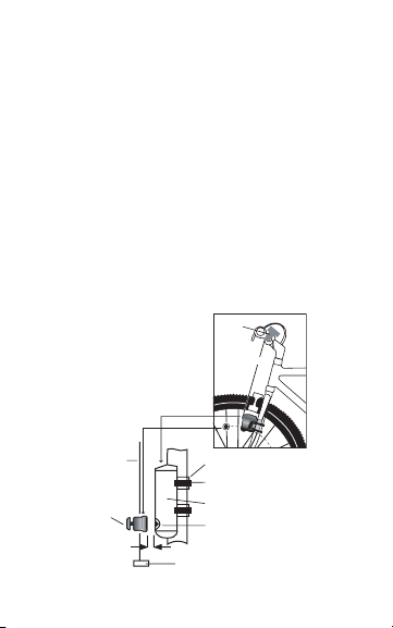
Attach the wheel magnet loosely to one of the spokes
on the same side of the wheel as the transmitter.
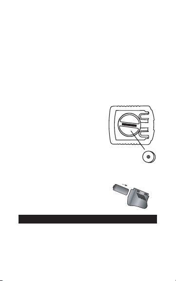
Adjust the position of the magnet and transmitter by
sliding both pieces up or down until the magnet pass-
es the alignment mark on the transmitter with a clear-
ance of 1-3mm (1mm is about the thickness of a
penny). See Figure 6. If the magnet and transmitter
are not close enough, computer readings will be
inconsistent, erratic or completely absent. Most prob-
lems that occur when installing a new computer are
related to magnet and sensor alignment and spacing.
STEP 3
Once the transmitter and wheel magnet are aligned
properly, securely tighten both in place.
TEST OF INSTALLATION
Once the installation procedure is complete, test the
unit to make sure everything is adjusted and working
properly.
STEP 1
Pick up the front end of the bicycle and spin the front
wheel. The computer should register a speed reading
within 1-2 seconds. If it does not, check the alignment
of the wheel magnet and transmitter, and make sure
that the space between the magnet and transmitter is
3mm or less. Adjust as necessary and re-test.
Note: Wireless cyclocomputers are occasionally
affected by electromagnetic interference. Common
sources of electromagnetic signals include high volt-
age power lines, motor driven equipment and other
wireless devices (such as heart rate monitors). If you
experience unusually high speed readings, check
your surroundings for possible sources of electro-
magnetic signals and move away from the source.
Made in China, V.1 – April 2004
Table of contents
Other Ascent Bicycle Accessories manuals
Popular Bicycle Accessories manuals by other brands

Lupine
Lupine SL F StVZO manual

Wuxi LingDe Microelectronics
Wuxi LingDe Microelectronics LD902GL instruction manual

Cane Creek
Cane Creek Double Barrel owner's manual

M-WAVE
M-WAVE 640027 manual

TLI
TLI VOLspeed Ebike Tuning Giant Syncdrive Sport... Operating manual & installation guide

Rock The Bike
Rock The Bike Icycleta manual