ASCOM teleCARE IP User manual

17 July 2017 / Ver. PF3
TD 93021US
Installation Guide
teleCARE IP
Emergency Call System
17 July 2017 / Ver. PF3
TD 93021US
Installation Guide
teleCARE IP
Copyright © 2017 Ascom (US), Inc.
This document may not be copied in whole or in part or otherwise reproduced without prior
written consent from Ascom, except where specifically permitted under US and international
copyright law.
Disclaimer The information in this document is subject to change. Use this product only in accordance with
the instructions provided in the installation and user guide manuals. Use this product only in
accordance with the purposes for which it is designed. For the latest version of all Ascom teleC-
ARE documentation, contact your local supplier or visit the Ascom Partner Website at https://
www.ascom-ws.com.
Trademarks and patents The teleCARE name and logo are trademarks of Ascom.
Other trade names used in this document may be trademarks or registered trademarks of the
manufacturers or vendors of the respective products. This publication may contain examples of
screen captures and reports used in daily operations. Examples may include fictitious names of
individuals and companies. Any similarity to names and addresses of actual businesses or per-
sons is entirely coincidental.
HIPAA disclaimer All examples of personal or protected health information in this document are fictitious. Any
resemblance to a real person or facility is purely coincidental. The owners and users of this prod-
uct are solely responsible for complying with all applicable protected health information privacy
laws. The users, by their use of this product, agree to indemnify the manufacturer or seller of this
product against all claims, litigation, and suits filed for protected health information violations.
European Union directives The European directive “Waste Electrical and Electronic Equipment” (WEEE) aims to minimize
the impact of electrical and electronic equipment waste on the environment and human health.
To conform to this directive, electrical equipment marked with this symbol must not be disposed
of in European public disposal systems. European users of electrical equipment must now return
end-of-life equipment for disposal. Further information may be found on the following website:
www.recyclethis.info.
Battery Disposal This product may use sealed lead-acid batteries. Please refer to manufacturer instructions and all
state, provincial, and local codes for information, instructions and requirements regarding proper
disposal.
Environmental Requirements Refer to the installation guide and product data sheet for complete product ratings and informa-
tion.
Avoid exposing the device to direct sunlight or other heat sources.
Do not expose the device to open flame.
Keep the device away from excessive heat and moisture.
Protect your device from aggressive liquids and vapors.
Keep the device away from strong electromagnetic fields.
Terms used in this manual Specialized terms are used throughout this manual. The first time a term is used it is defined in
the text.
Regulatory Compliance
(EU/EFTA)
This equipment is intended to be used in the whole EU & EFTA.
This equipment is in compliance with the essential requirements and other relevant provisions of
EMC Directive 2014/30/EU and RoHS Directive 2011/65/EU. For NIRX/NITX/NILF/NICR/NIRD/
NUWGTW/NUREP/NUWIR/NUUTX/NUWBM3 products: Radio Equipment Directive 2014/53/EU
and RoHS Directive 2011/65/EU.
The Declaration of Conformity may be consulted at:
http://www.ascom-ws.com/doc/

17 July 2017 / Ver. PF3
TD 93021US
Installation Guide
teleCARE IP
Regulatory Compliance
(US/CAN)
Copyright
Safety Compliance:
The equipment described herein complies with:
ANSI/UL 2560 Emergency Call Systems for Assisted Living and Independent Living Facilities
CAN/CSA C22.2 No. 205 Signal Equipment
Note: This equipment has been tested and found to comply with the limits for a Class B digital
device, pursuant to Part 15 of the FCC Rules. These limits are designed to provide reasonable
protection against harmful interference in a residential installation. This equipment generates,
uses, and can radiate radio frequency energy and, if not installed and used in accordance with
the instructions, may cause harmful interference to radio communications.
However, there is no guarantee that interference will not occur in a particular installation. If this
equipment does cause harmful interference to radio or television reception, which can be deter-
mined by turning the equipment off and on, the user is encouraged to try to correct the interfer-
ence by one or more of the following measures:
Reorient or relocate the receiving antenna.
Increase the separation between the equipment and receiver.
Connect the equipment into an outlet on a circuit different from that to which the receiver is
connected.
Consult the dealer or an experienced radio or television technician for help.
Information to user:
This device complies with Part 15 of the FCC Rules. Operation is subject to the following two
conditions: i) this device may not cause harmful interference, and ii) this device must accept any
interference received, including interference that may cause undesired operation.
This device complies with Industry Canada license-exempt RSS standard(s). Operation is subject
to the following two conditions: (1) this device may not cause interference, and (2) this device
must accept any interference, including interference that may cause undesired operation of the
device.
Le présent appareil est conforme aux CNR d'Industrie Canada applicables aux appareils radio
exempts de licence. L'exploitation est autorisée aux deux conditions suivantes:
(1) l'appareil ne doit pas produire de brouillage, et
(2) l'utilisateur de l'appareil doit accepter tout brouillage radioélectrique subi, même si le brouil-
lage est susceptible d'en compromettre le fonctionnement. CAN ICES-3 (B)/NMB-3(B)
Modifications:
Changes or modifications to the equipment not expressly approved by the party responsible for
compliance could void the user's authority to operate the equipment.
NIRC3 (only)
Note: This equipment has been tested and found to comply with the limits for a Class A digital
device, pursuant to part 15 of the FCC Rules. These limits are designed to provide reasonable
protection against harmful interference when the equipment is operated in a commercial envi-
ronment. This equipment generates, uses, and can radiate radio frequency energy and, if not
installed and used in accordance with the instruction manual, may cause harmful interference to
radio communications. Operation of this equipment in a residential area is likely to cause harm-
ful interference in which case the user will be required to correct the interference at his own
expense. CAN ICES-3 (A)/NMB-3(A)
NIFX, NIRX and NITX (only)
These devices comply with RSS-310 of Industry Canada. Operation is subject to the condition
that these devices do not cause harmful interference.

17 July 2017 / Ver. PF3
TD 93021US
Installation Guide
teleCARE IP
Contents
1 Introduction ..................................................................................................................................1
1.1 General ..................................................................................................................................1
1.2 Installation and Commissioning ...............................................................................................1
1.3 teleCARE IP With Speech ........................................................................................................2
2 Practical Engineering Parameters ...............................................................................................4
2.1 General Limitations .................................................................................................................4
2.2 Network Expectations .............................................................................................................4
2.3 VoIP Requirements (Supplementary) ........................................................................................5
2.4 teleCARE IP Compatible Ascom Handsets (Supplementary) ......................................................5
3 System LAN Cabling .....................................................................................................................6
3.1 Ethernet Switch ......................................................................................................................6
3.2 Ethernet LAN and Room Bus Cables ........................................................................................7
4 System Power .............................................................................................................................10
4.1 24Vdc / 3 Amp Power Supply (Standard) ...............................................................................10
4.2 24Vdc / 8 Amp Power Supply (Seismic) .................................................................................12
4.3 Secondary Power ..................................................................................................................16
4.4 teleCARE IP Power Supply Wiring ..........................................................................................16
4.5 Power Supply Unit (24Vdc) with Multiple Power Buses ..........................................................17
4.6 Maintenance and Service ......................................................................................................18
5 Control Equipment .....................................................................................................................19
5.1 Preparation ...........................................................................................................................19
5.2 Room Controller (NIRC3) .......................................................................................................19
5.3 Preparing the Room Bus and Power Cables ...........................................................................25
5.4 Voice Piggy Back (NIVP) .........................................................................................................29
5.5 Connection Terminals ............................................................................................................31
5.6 Connecting the IP Room Controller Printed Circuit Board ......................................................35
5.7 LED Lamp Boards (NILD2) ......................................................................................................38
5.8 Corridor Lamp (NICL2) ..........................................................................................................43
5.9 System Manager (NISM2) ......................................................................................................51
6 Peripherals ..................................................................................................................................56
6.1 Preparation ...........................................................................................................................56
6.2 Installation Instructions .........................................................................................................56
6.3 Backplates and Surface Mounting Spacer .............................................................................57
6.4 Switch Module Electrical Connections ...................................................................................60
6.5 Bedside Module (NIBM2) ......................................................................................................68
6.6 Medical Rail Socket (NIMS2) ..................................................................................................72
6.7 Door Side Module (NIDM) .....................................................................................................77
6.8 Pull Cord Module - Active (NIPC-W3A) ..................................................................................78
6.9 Toilet Cancel Module - Active (NITC-XXA) .............................................................................80
6.10 Pull Cord Module - Passive (NIPC-XXP) ................................................................................81

17 July 2017 / Ver. PF3
TD 93021US
Installation Guide
teleCARE IP
6.11 Toilet Cancel Module - Passive (NITC-XXP) ...........................................................................82
6.12 Pull Cord Module (NIPC2) Active and Passive .......................................................................83
6.13 Duty Selector (NIDS) ............................................................................................................94
6.14 Card Reader (NICR) .............................................................................................................97
6.15 Speech Module (NISP) .......................................................................................................101
6.16 Room Display (NIRD) .........................................................................................................103
6.17 Television Interface Module ...............................................................................................110
6.18 Sunblind Control Module ..................................................................................................112
7 External Inputs .........................................................................................................................114
7.1 Switch modules compatible with NICB ................................................................................114
7.2 Other switch modules with external inputs .........................................................................114
7.3 Preparation .........................................................................................................................114
7.4 NICB-kit ..............................................................................................................................115
7.5 Connection Board ...............................................................................................................116
7.6 Bed Module (NIBM2) and Pull Cord Module - Active (NIPC-XXA) .........................................118
7.7 Door Side Module (NIDM) and Toilet Cancel Module - Active (NITC-XXA) ............................119
7.8 Room Display (NIRD) ...........................................................................................................122
8 Wireless Functionality .............................................................................................................125
8.1 General ..............................................................................................................................125
8.2 Principle of the teleCARE IP with Wireless Functionality .......................................................126
8.3 teleCARE Wireless with Speech ...........................................................................................128
8.4 teleCARE IP Wireless Planning .............................................................................................131
8.5 teleCARE IP Wireless Components ......................................................................................137
9 Installation Examples ...............................................................................................................159
9.1 2-Bed Room with Active Toilet Cancel and Active Pull Cord Peripherals ...............................159
9.2 2-Bed Room with Passive Toilet Cancel and Passive Pull Cord Peripherals .............................161
9.3 2-Bed Room with a Medical Rail Socket at each Bed ...........................................................163
9.4 Room Controller with Corridor Lamps (Master/Slave) ..........................................................165
9.5 4-Bed Room with Speech ....................................................................................................167
9.6 Duty Selector at a staff Station ............................................................................................169
9.7 Positioning of the teleCARE IP Peripherals ...........................................................................171
Document History .......................................................................................................................173

TD 93021US
17 July 2017 / Ver. PF3 1
Installation Guide
teleCARE IP
1 Introduction
The installation guide covers the mechanical and electrical installation of the teleCARE IP Emergency Call
System. The teleCARE IP “System Description” (TD 92608GB) should be read before reading this manual
to gain a general understanding of the teleCARE IP system.
Throughout this document there are “cross-references” in the text which indicate that further details can
be found in another section of this document. The cross-references are colored blue and linked to the
relevant place in the document. Positioning the cursor over the “cross-reference” then click the left
mouse button to go to the relevant section of the document. The product illustrations in this document
represent the products when the illustrations were created. The actual appearance of the products may
vary due to subsequent technical modifications and component changes.
Many devices in this manual are static sensitive. When you see this icon in the manual,
observe all proper handling procedures for static sensitive devices.
1.1 General
teleCARE IP is a Local Area Network (LAN) based Emergency Call System for assisted living and
independent living facilities. The LAN/WLAN infrastructure is used to communicate the information
generated in the emergency call system, such as calls for help or assistance, staff presence, emergency
alarms, technical alarms, etc. The IP integration is at room level with at least one IP port per room.
teleCARE IP operates on a Ethernet LAN based on 10/100 BaseT, using a Cat 5 (or higher) structured
wiring for 100 BaseT. The network shall be a dedicated network.
The teleCARE IP system is modular, scalable and built around the Room Controller (NIRC3). Power is
supplied using an external 24Vdc power supply.
teleCARE IP peripherals are connected to the room controller by a digital room bus. Each room controller
includes four room buses with eight addresses per bus.
In a teleCARE IP Emergency Call System the maximum number of individual call locations must not
exceed 200.
The modularity of teleCARE IP makes it easy to extend and add new functions to already installed
systems. The LAN technology allows easy installation of new room controllers and peripherals in order to
extend the existing teleCARE IP system.
1.2 Installation and Commissioning
The installation and commissioning of teleCARE IP should only be undertaken by qualified technicians
and carried out in accordance with all regulations. Only original teleCARE IP parts and components are to
be used in any teleCARE IP installation. In order for the system to function properly these parts must be
installed in accordance with the appropriate teleCARE IP installation instructions.
The teleCARE IP equipment should only be installed when the building work is completed and when the
environment is clean, dry and totally weatherproof. All control and distribution equipment must be
accessible for commissioning and servicing.
The acceptable environmental conditions for the teleCARE IP system, associated power supplies and
related equipment are all listed systems and components and are in compliance with the safety
requirements of ANSI/UL 2560 Standard for Safety, Emergency Call Systems for Assisted Living and
Independent Living Facilities and CAN/CSA No. 205-12, Signal Equipment.
WARNING: The teleCARE IP equipment should not be installed in areas where the air pressure is
below 850 millibar (approximate maximum altitude of 6100ft (2000m)).

TD 93021US
17 July 2017 / Ver. PF3 2
Installation Guide
teleCARE IP
WARNING: teleCARE IP components, including all handsets, are not intended for use in oxygen
enriched environments.
WARNING: teleCARE IP components, including all handsets, are not intended for use in rooms
where flammable (anesthetic) gases are used.
1.3 teleCARE IP With Speech
The basic installation for a teleCARE IP system with speech is the same as for teleCARE IP without speech
with the exception that room controllers with speech support and a supplementary VoIP gateway are
required. In addition each location where speech is required must have a teleCARE IP speech module. The
speech module can only be used in combination with the teleCARE IP door side module (NIDM), the
bedside module (NIBM), and the pull cord module (NIPC).
1.3.1 Compatible Ascom IM Handsets
teleCARE IP with speech is designed to work with Ascom Interactive Messaging using the Ascom
handsets which support multi-layer interactive messaging. At the time of publication of this document
the Ascom handsets which support multi-layer interactive messaging are:
9d24 / mkII (software 3.71 or higher)
d62 (software 3.0.5 or higher)
d81 (software 2.0.5 or higher)
i62
i75 (software 1.7.7 or higher)
1.3.2 System Overview teleCARE IP with Speech
The following illustration shows a typical example of a teleCARE IP speech system. The options and
system components depend on the specific project requirements.
Figure 1. System overview teleCARE IP with speech
1.3.3 ESPA and TAP Paging System Interface
With the appropriate license, the NISM2 serves as the interface between the teleCARE IP system and ESPA
or TAP paging systems.

TD 93021US
17 July 2017 / Ver. PF3 3
Installation Guide
teleCARE IP
1.3.4 Innovaphone VoIP Gateway
The teleCARE IP system uses the supplementary Innovaphone VoIP gateway to support VoIP speech
functionality. The Innovaphone VoIP gateway is an IP based gateway providing the VoIP based solution
which supports all the features of a traditional PBX. For the teleCARE IP VoIP the SIP Trunk must be used
for the interface to the main PBX. The SIP trunk must be set to “Early offer”.For more information refer to
the teleCARE IP Configuration Manual TD 93019US.
The Innovaphone VoIP gateway is powered by a mains adapter power supply (output 40Vdc 375mA). It is
connected and integrated in the existing telephone system network directly using SIP protocol. It is
configured with the project specific requirements using the teleCARE IP System Manager.
A license is required for the Innovaphone VoIP gateway. For this an activation code has to be ordered
from Ascom before downloading the license from the Innovaphone Customer Portal (https://
my.innovaphone.com/).

TD 93021US
17 July 2017 / Ver. PF3 4
Installation Guide
teleCARE IP
2 Practical Engineering Parameters
In order to ensure the optimal performance of a teleCARE IP system it is important to consider certain
parameters and limitations. The following tables show the most important practical values which can
have an influence on the teleCARE IP system performance.
WARNING: Any deviation from the values and recommendations shown in the following tables
can significantly reduce the performance of the teleCARE IP system.
2.1 General Limitations
2.2 Network Expectations
teleCARE IP Items Practical Limits
NIRC3s per NISM Max. 200
Active peripherals per room bus (addressable - 0 to 3) Max. 4
Active peripherals per room bus (fixed address - 4 to 7) Max. 4
Pull cord peripherals on a passive bus Max. 1
Toilet cancel peripherals on a passive bus Max. 1
Total cable length of an NIRC3 IP room bus Max. 100 feet (30 meters)
Minimum IP room bus voltage 4.5 Vdc
Network Expectations
The LAN installation must be certified and tested in accordance with
ANSI/TIA/EIA-568-A.
The LAN must be dedicated and isolated from any general purpose LAN
The LAN installation should be in accordance with ANSI/TIA/EIA-568-A
LAN cable type: Category 5 (or higher)
Maximum LAN cable length: 328 ft (100 meters)
The LAN must only use switching equipment listed in UL file E360946.
A switch port is required for each room controller
Existing customer LANs must be assessed by Ascom before committing
(not applicable for UL2560 installations which prohibit use of customer LAN's)
For details of the teleCARE IP load and performance see document TD92636GB,
(IP Infrastructure Requirements)

TD 93021US
17 July 2017 / Ver. PF3 5
Installation Guide
teleCARE IP
2.3 VoIP Requirements (Supplementary)
2.4 teleCARE IP Compatible Ascom Handsets (Supplementary)
VoIP Considerations
The Innovaphone VoIP gateway version 10 (or later) is required for teleCARE IP with
speech, as the interface to the PBX.
An interoperability test between the VoIP gateway and main PBX must be performed.
The connection between the PBX and the Innovaphone can be PRI or SIP Trunk
teleCARE IP only supports CODEC G.711 (a-law)
SIP trunk to the VoIP gateway must be set to “Early offer”
teleCARE VoIP shall use the Emergency Call System LAN only.
Ascom Recommendations:
Delay - less than 50 ms is good
Jitter - less than 30 ms is good
Packet Loss - 1% is good (up to 4% is acceptable)
The maximum capacity of the network used for voice should not exceed 25% of the
total network capacity
The maximum capacity of the network used for data and voice together should not
exceed 75% of the total network capacity
teleCARE IP Compatible Ascom Handsets
9d24 / mkII (software 3.71 or higher)
d62 (software 3.0.5 or higher)
d81 (software 2.0.5 or higher)
i62
i75 (software 1.7.7 or higher)

TD 93021US
17 July 2017 / Ver. PF3 6
Installation Guide
teleCARE IP
3 System LAN Cabling
3.1 Ethernet Switch
The 8-port Ethernet Switch, Ascom part number APS5001, shall be used with the teleCARE IP system and
can be purchased through Ascom.
WARNING: Use of any Ethernet Switch other than Ascom part number APS5001 violates the UL
2560 listing.
3.1.1 Ethernet Switch DIN Rail Mounting
The Ethernet Switch shall be mounted on a 1.5in (35mm) DIN-rail, which can be mounted on a wall. See
instructions inside the Ethernet Switch Installation Guide provided with the switch.
3.1.2 Ethernet Switch 19” Rack and Cabinet Mounting
The Ethernet Switch can be mounted into a 19in (483mm) rack secured to a DIN Rail, which must be
attached with screws or other fixtures to the rack and must not be easily movable.
3.1.3 Ethernet Switch Installation – Seismic
For installations requiring seismic considerations, refer to OSHPD Installation Requirements and
Instructions, document number 3101998, for selection, sourcing, and installation of racks and cabinets.
After the racks or cabinets are installed, the Ethernet Switch can then be installed into a cabinet or rack,
in accordance with the instructions described in 3.1.2.
WARNING:
• Use only the cabinets or rack listed in the OSHPD Installation Requirements and Instructions
document (P/N 3101998).
• Do not use the uninterruptible power supplies described in the OSHPD installation document. The
battery backup for the teleCARE IP system must be provided by the power supply described in
section 4.2, 24Vdc / 8 Amp Power Supply (Seismic).
• Use the rack mounting accessories described in section 3.1.2 to mount the Ethernet switch to the
rack or cabinet.
• Do not apply the OSHPD Label to the rack, cabinet or, Ethernet Switch. If an OSHPD label is
required, contact your Ascom Sales Representative.
3.1.4 Ethernet Switch Power
The Ethernet Switch must be powered by the 24Vdc / 3 Amp Power Supply Ascom model APS5000
described in Section 4 of this manual. The power conductors must be in accordance with the
requirements specified in section 4.4 and connected to the four-pin removable keyed connector provided
with the unit. Power connections to the Ethernet Switch shall be in accordance with the Figure 2.
Figure 2. Ethernet Switch Power Connection
TD 93021US
17 July 2017 / Ver. PF3 7
Installation Guide
teleCARE IP
3.1.5 Ethernet Switch Operation
When properly installed and operating, LED indicators on the Ethernet Switch will be observed as follows:
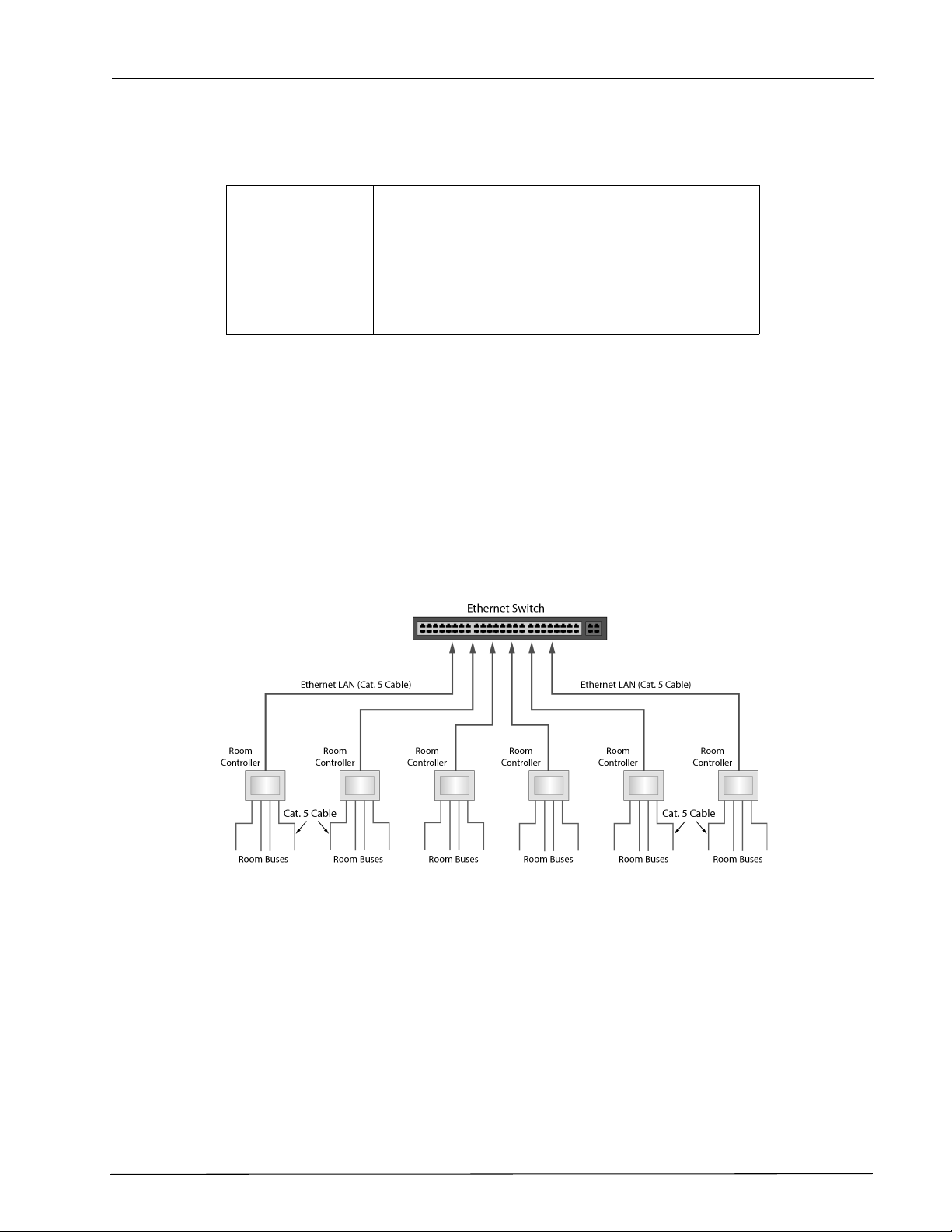
3.2 Ethernet LAN and Room Bus Cables
High quality cables must be used to install the teleCARE IP system. The individual wire cores of the cables
should be color coded. Care should be taken when stripping cables from the outer mantle to avoid
damaging the insulation of the wire cores.
The system wiring is classified as low voltage and therefore cabling must be separated from higher
voltage system through the use of separate conduits or divided cable trays.
A minimum of 19.75in (50cm) of free cable should be left at the location of the room controllers, and
corridor lamps. For the room peripherals a minimum of 6in (15cm) of free cable should be left at the
location of each peripheral. All cables should be clearly marked at both ends.
Figure 3. Ethernet LAN and room bus cabling
Note: Suitable existing wiring could also be used for the room bus. Contact your local
representative for further information.
PWR (green) Illuminates steady when proper power is supplied to
the Ethernet Switch.
LINK (green) Each port has a LINK LED which indicates that a valid
Ethernet link has been established. The LED flashes
when data transfer is occurring.
HS (yellow) Each port has a DATA RATE LED which illuminates
steady indicating that data is transferring at 100 Mbps.
TD 93021US
17 July 2017 / Ver. PF3 8
Installation Guide
teleCARE IP
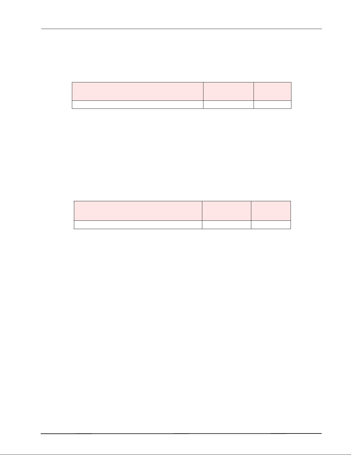
3.2.1 Ethernet LAN Cable
The cable required for the Ethernet LAN must comply with the specification TIA/IEA 568-A Category 5 or
higher. This is a standard 4 x unshielded twisted pair (UTP) solid bare copper with a diameter of 24 AWG
(0.5mm).
Table 1. Recommended Ethernet LAN cable
Caution: The maximum length of the Cat 5 (or higher) Ethernet LAN cable is 328 feet/100
meters.
3.2.2 Room Bus Cable
The room bus cable connects the room controller to the associated teleCARE IP peripherals. It consists of
four wires which carry 5.5 volts, Data, Voice and Ground.
The recommended cable for the room bus is TIA/IEA 568-A Category 5 or higher. It is also acceptable to
use 2 x twisted pairs of solid copper wires each 20 AWG (0.8mm). The table below shows the
recommended cable type and maximum cable length.
Table 2. Recommended teleCARE room bus cable
Room Bus Cable Considerations
It is important to consider the factors of cable length and load when installing the room bus for the
following reasons:
• The resistance of the wires in the room bus cable increases with the length and this causes the
voltage to decrease progressively along the length of the cable.
• The room bus voltage also drops in proportion to the load.
• The effect of “cross-talk” increases as the cable length increases.
Room Bus Power Considerations
The room bus power supply output from the room controller is limited to 500mA per room bus but the
maximum acceptable load on the room bus decreases significantly as the distance from the room
controller increases due to the resistance of the room bus cable.
Room Bus Voltage Considerations
The power supply to the room bus at the output from the room controller is >5.5Vdc without load but
this will drop as the room bus cable length and/or the load increases. The minimum acceptable voltage at
any point on the room bus cable is 4.5Vdc.
Room Bus Cable Length and Power Limitations
The IP Room Controller offers up to four room buses. The load of any room bus must not exceed 300mA
and the minimum acceptable voltage anywhere along the room bus is 4.5 volts.
Cable Type Wire Size
Diameter / AWG
Max. Cable
Length
TIA/IEA 568-A, Category 5 or higher (4 x UTP) 24 AWG (0.5mm) 328ft (100m)
Cable Type Wire Size
Diameter / AWG
Max. Cable
Length
TIA/IEA 568-A Category 5 or higher (4 x UTP) 24 AWG (0.5mm) 98.4ft (30m)

TD 93021US
17 July 2017 / Ver. PF3 9
Installation Guide
teleCARE IP
When UTP category 5 cable (or higher) is used the length of any room bus cable should not exceed 98.4ft
(30m), irrespective of the load. Below 98.4ft (30m), the maximum acceptable length of the room bus
cable depends on the load.

TD 93021US
17 July 2017 / Ver. PF3 10
Installation Guide
teleCARE IP
4 System Power
The teleCARE IP system power supply shall be sourced from an external 24Vdc power supply, utilizing a
dedicated 2-wire power distribution bus. The external power requirement for teleCARE IP is 24Vdc, with
an acceptable range of 21.6Vdc to 26.4Vdc.
WARNING: Use of any Power Supply other than those which are specified in this manual violates
the UL 2560 listing.
4.1 24Vdc / 3 Amp Power Supply (Standard)
The 24Vdc / 3 Amp Power Supply, Ascom part number APS5000, must be used with the teleCARE IP
system and can be purchased through Ascom.
The teleCARE IP Standard Power Supply shall be used to power the teleCARE IP system. This power
supply converts 115Vac / 60Hz input power to a 24Vdc / 3 Amp, Class 2 Rated regulated output.
There is a built-in charger to charge sealed lead acid batteries. The batteries provide the Secondary Power
to the teleCARE IP system in the event of mains AC power failure. There is an automatic switchover to the
batteries when input AC power fails. During switchover, there is zero voltage drop at the power output.
The power output fuse is rated at 15A/32Vdc.
WARNING:
• Do not use the Standard Power Supply for installations that require seismic considerations. Use the
24Vdc / 8 Amp Power Supply (Seismic) described in section 4.2 instead.
• Make certain that the AC circuit breaker is off before making any wiring connections between the
circuit breaker and the power supply.
• Always de-energize the power supply prior to servicing.
• When servicing, the AC mains circuit breaker should be in the off position and locked out to
prevent accidental activation.
• When necessary, always replace the fuse with the same type and rating (15A/32Vdc).
• This power supply is intended for indoor use only. Do not expose the unit to rain or moisture.
• After installation or servicing make sure that the cover is secured with the provided Key Lock.
4.1.1 Power Supply (Standard) Installation
The teleCARE IP Standard Power Supply is provided with an Installation Guide that is packaged with the
unit. The unit is intended for wall mounting at a fixed location. Follow the instructions in the Installation
Guide for mounting the power supply to a wall.
Note: Power distribution is best organized with the power supply unit located as close as
possible to the rooms which it powers. This minimizes the voltage drop caused by the
length of the power supply wires and the load of the powered teleCARE IP system devices.
For setup and configuration, refer to the illustrations in the Installation Guide to identify the switch which
must be set for 24Vdc operation, and to identify the terminals for connecting the power supply board to
the batteries and teleCARE IP system.

TD 93021US
17 July 2017 / Ver. PF3 11
Installation Guide
teleCARE IP
WARNING:
• Batteries must be secured within the HPFF8 cabinet enclosure.
• Batteries must be lead acid and must comply with UL 2054. (See Section 4.3 Secondary Power.)
• Before applying power, inspect the Power Supply Board (Figure 1 in the Power Supply Installation
Guide) to ensure that SW1 is set to the Open position, to configure the unit for 24Vdc operation.
• Before applying power, inspect the Power Supply Board to ensure that jumper J1, AC Delay, is in
place.
• The Power Supply Board is not wired to chassis ground. When connecting the mains AC grounding
conductor, DO NOT connect to the G terminal on the Power Supply Board.
• Use a crimping wire nut of appropriate size to connect the mains AC grounding conductor to the
green with yellow stripe grounding conductor lead attached to the power supply cabinet
backpanel.
• Measure the output voltage at the [+BAT-] and [+DC-] terminals before connecting the batteries or
teleCARE IP system. Improper high voltage will damage the connected devices.
• Always de-energize the power supply unit prior to connecting the batteries and teleCARE IP
system.
• Refer to sections 4.4 and 4.5 in this manual before connecting and powering the teleCARE IP
system.
Connect the AC main power (115Vac/60Hz) to the terminals marked [L, N] on the Power Supply Board.
Apply mains AC power. Measure and confirm 20Vdc to 26.4Vdcat the [+BAT-] and [+DC-] terminals.
Adjust the potentiometer next to SW1 to get 26.4Vdc at the [+BAT-] terminals. De-energize the power
supply, connect the batteries and teleCARE IP system, and re-energize the power supply.
Figure 4. Adjust the voltage to 26.4 Vdc
4.1.2 Power Supply (Standard) Operation and Maintenance
The teleCARE IP Standard Power Supply should be tested at least once a year for proper operation. Under
normal load conditions, the DC output voltage should be checked for proper voltage level, which is
24Vdc for the teleCARE IP system.
Under normal load conditions, check that the battery is fully charged. Check for the specified voltage
(24Vdc) at both the battery terminals and power supply board terminals marked [+BAT-] to ensure there is
no break in the battery connection wires.
Voltage Adjustment

TD 93021US
17 July 2017 / Ver. PF3 12
Installation Guide
teleCARE IP
Note:
• The maximum charging current under discharge is 0.7 amperes.
• Expected battery life is 5 years. However, it is recommended to change the batteries in 4 years, or
less if needed.
Table 3. Power Supply Board LED Diagnostics (Red DC / Green AC)
Table 4. Power Supply Board LED Diagnostics (Red BAT)
4.2 24Vdc / 8 Amp Power Supply (Seismic)
For installations requiring Seismic compliance, the only external power supply which is certified for use
with the teleCARE IP system is model HPFF8 by Honeywell Power Products, which can be purchased
through an electrical supplier such as, Graybar or Arrow.
Note: The HPFF8 is listed under OSHPD Special Seismic Certification Pre-Approval:
OSP-0071-10.
The HPFF8 power supply converts 115Vac / 60Hz input power to 24Vdc / 8 Amps of continuous power
output, distributed through four supervised power limited output circuits. The maximum current for any
one output circuit is 3.0 Amperes. Each power output circuit has built in fault detection and automatic
recovery when faults are removed.
There is a built-in charger to charge sealed lead acid batteries. The batteries shall provide Secondary
Power to the teleCARE IP system in the event of mains AC power failure. There is an automatic
switchover to the batteries when input AC power fails. During switchover, there is zero voltage drop at
the power output.
WARNING:
• Batteries must be secured within the HPFF8 cabinet enclosure using Seismic Installation Kit
(SEISKIT-COMMENC).
• Batteries must be lead acid and must comply with UL 2054. (See section 4.3, Secondary Power.)
• The HPFF8 Power Supply is a UL 864 listed power supply, normally intended to power and function
with a Fire Alarm System (FAS). When used to power the teleCARE IP system, the features normally
required to make the power supply operational as a FAS unit are not supported by Ascom.
• Except for the instructions for mounting the unit to a wall, which are provided in the HPFF8
Installation and Operation Manual, follow only the instructions provided in this manual for safety,
setup, configuration, and wiring to the teleCARE IP system.
Red (DC) Green (AC) Power Supply Status
ON ON Normal operating condition.
ON OFF Loss of AC, Stand-by battery supplying power.
OFF ON No DC output.
OFF OFF Loss of AC. Discharged or no stand-by battery. No DC
output.
Red (BAT) Battery Status
ON Normal operating condition
OFF Battery fail/low battery

TD 93021US
17 July 2017 / Ver. PF3 13
Installation Guide
teleCARE IP
• Make certain that the AC circuit breaker is off before making any wiring connections between the
circuit breaker and the power supply.
• Always de-energize the power supply prior to servicing.
• When servicing, the AC mains circuit breaker should be in the off position and locked out to
prevent accidental activation.
• This power supply is intended for indoor use only. Do not expose the unit to rain or moisture.
• After installation or servicing make sure that the cover is secured with the provided Key Lock.
4.2.1 Power Supply (Seismic) Installation
The HPFF8 Power Supply is provided with an Installation Manual that is packaged with the unit. The unit
is intended for wall mounting at a fixed location. Follow the instructions for Backbox Mounting of a
Standard Cabinet provided in the Installation Manual.
Note: Power distribution is best organized with the power supply unit located as close as
possible to the rooms which it powers. This minimizes the voltage drop caused by the
length of the power supply wires and the load of the powered teleCARE IP system devices.
For setup and configuration, use the illustrations provided in the HPFF8 Installation Manual to identify the
locations of jumpers and terminals. Follow the instructions in this manual for connecting the power
supply board to the batteries and teleCARE IP system
Inspect the Control Circuit Board (Figure 1.1 in the HPFF8 Installation Manual) to ensure that the Charger
Disable Jumper (J1) and Ground Fault Disable Jumper (J2) are both installed.
Install the Reference Resistor to the REF+ and REF- terminals on TB3. Use either a 3.9K or 4.7k ohm, ¼
watt resistor as the Reference Resistor.
Caution: The same value resistor used for the Reference Resistor must be used as the End of
Line (EOL) resistor for the teleCARE IP system power bus.
Before connecting and powering the teleCARE IP system, refer to sections 4.4 and 4.5 in this manual.
Install the EOL resistor at the last NIRC3 unit on the teleCARE IP power bus.
Caution: Measure the output voltage at the [+BAT-] and [+DC-] terminals before connecting
the batteries or teleCARE IP system. Improper high voltage will damage the connected
devices.
Caution: Always de-energize the power supply unit prior to connecting the batteries and
teleCARE IP system.
Caution: Maintain vertical separation where power-limited (i.e., DC power to teleCARE IP) and
non-power-limited circuits (i.e., mains AC and battery wiring connections to the Control
Circuit Board) appear to cross.
Before connecting and powering the Secondary Power Batteries, the batteries must be secured within the
HPFF8 cabinet enclosure using the Seismic Installation Kit. Follow the instructions provided with
Honeywell model SEISKIT-COMMENC.
Connect the AC mains power (115Vac/60Hz) to the TB1 terminals marked [L1, Ground, L2] on the HPFF8
Power Supply Board.
Apply mains AC power. Measure and confirm 24Vdc at the [+BAT-] and [1L1/1L2 through 4L1/4L2 and
A+/A-] terminals.
De-energize the power supply, connect the batteries and teleCARE IP system (to the 4L1/4L2) terminals.

TD 93021US
17 July 2017 / Ver. PF3 14
Installation Guide
teleCARE IP
Caution: Connect the negative (-) lead of the teleCARE IP System to the 4L1 terminal and the
positive (+) lead to the 4L2 terminal.
Re-energize the power supply.
4.2.2 Power Supply (Seismic) Operation and Maintenance
The HPFF8 Power Supply should be tested at least once a year for proper operation. Under normal load
conditions, the DC output voltage should be checked for proper voltage level, which is 24Vdc for the
teleCARE IP system.
Under normal load conditions, check that the battery is fully charged. Check for the specified voltage
(24Vdc) at both the battery terminals and power supply board terminals marked [+BAT-] to ensure there is
no break in the battery connection wires.
Note:
• The maximum charging current under discharge is 0.75 amperes.
• Expected battery life is 5 years. However, it is recommended to change the batteries in 4 years, or
less if needed.
The HPFF8 provides supervised functions of the field wiring for the following adverse conditions:
• Field-wiring fault (short or open) on the teleCARE IP power bus.
• AC failure or brownout at the power supply.
• Battery failure (no battery or battery voltage less than 20.5Vdc) condition at the power supply.
• Battery charger failure on the power supply.
• Ground fault condition.
• +/- Reference Resistor
There are 8 LEDs on the Control Circuit Board for indicating normal and trouble operation of the HPFF8
Power Supply (see Figure 1.1 in the HPFF8 Installation Manual.) When viewed from top to bottom, the
LEDs operate as follows:

TD 93021US
17 July 2017 / Ver. PF3 15
Installation Guide
teleCARE IP
Table 5. Control Circuit Board LED Diagnostics
Note:
1Relates to the A+/A- terminals on TB4. Not used in teleCARE IP.
2A battery fail indication can occur if there was an AC failure within the first 24 hours
after initial power-up and the battery voltage had been discharged to a voltage of
20.5Vdc or less. The BAT TRBL LED may also illuminate steady, after a certain delay
during charging, to indicate the battery was discharged and may not support full
load. The delay is based on operational conditions (time remaining in the first 24
hours and time in stand-by) and will automatically reset if the battery charging has
time to reach its full float voltage.
3SIG4 TRBL through SIG1 TRBL associate with TB4 terminals 4L1/4L2 through 1L1/1L2
respectively.
4The HPFF8 has Trouble Memory for the supervised outputs. This is useful as an aide in
knowing when past troubles have occurred and if intermittent problems are present
on the SIG4 through SIG1 output circuits.
5If all four SIG TRBL LEDs are illuminated steady, check if the Reference Resistor is
missing or doesn’t match the EOL resistor used to terminate the teleCARE IP Power
Bus. Otherwise, each power circuit probably has a problem.
LED Label Condition Illumination Reset
1PWR ON Power On Steady Auto
Loss or Brownout Blink
2AUX TRBL Note 1 Normal Off Auto
Excessive load or short Steady
3BAT TRBL Note 2
Normal Off
Auto
Charger Fault Blink
No battery or <20.5Vdc Steady
4GF TRBL Normal Off Auto
Ground Fault Steady
5SIG4 TRBL Note 3
Normal Off Auto
Short or Open Present Steady Note 5
Short or Open Past Note 4 Blink Note 6
6SIG3 TRBL Note 3
Normal Off Auto
Short or Open Present Steady Note 5
Short or Open Past Note 4 Blink Note 6
7SIG2 TRBL Note 3
Normal Off Auto
Short or Open Present Steady Note 5
Short or Open Past Note 4 Blink Note 6
8SIG1 TRBL Note 3
Normal Off Auto
Short or Open Present Steady Note 5
Short or Open Past Note 4 Blink Note 6
Table of contents
Other ASCOM Emergency Phone manuals


