MediPendant MED01 User manual

INSTALLING YOUR MediPendant™
This is for basic installation of your MediPendant™. Please see OWNER’S MANUAL
for full instructions, product details, warranties and disclaimers.
Model #MED01
MediPendant™
STEP 1
Place the MediPendant™base station on a stable surface located near a power outlet
and an available phone jack. For best results, locate the base station in an area away
from household appliances which could present electrical interference. See Fig. 1
If you are using more than one MediPendant™ system in your home, we recommend
that you place the base stations at least 15 ft. apart from each other.
STEP 2
Grab RED TAB located on side of base station and pull it straight out. Removing tab
activates back-up battery. See Fig. 2
Unit will beep continuously and the POWER LED and PHONE LINE INDICATOR LED
will both flash RED until AC/DC adapter is plugged in. See STEP 3.
Fig. 2
Fig. 1
Phone
Jack
Power
Outlet
QUICK START GUIDE
10 STEP
1

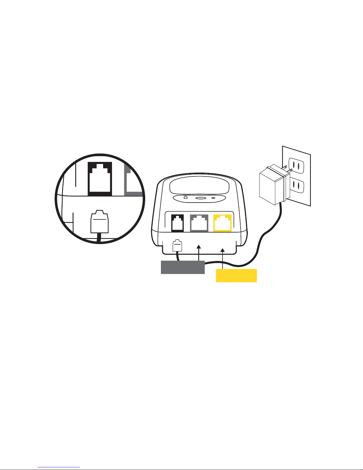
STEP 3
Connect the AC/DC Adapter into the BLACK plug in the back of the base station
marked DC. See Fig. 3
STEP 4
Connect the other end of the AC/DC Adapter into a standard power outlet. See Fig. 4
Once plugged in, your base unit will continue to beep and the RED PHONE LINE
INDICATOR LED will continue to flash. The POWER LED will change from flashing
RED to solid GREEN.
NOTE: DO NOT PLUG THE AC/DC ADAPTER INTO A POWER OUTLET WHICH IS
CONTROLLED BY A WALL SWITCH. If the switch is accidently turned off, the system
will begin to beep indicating a loss of power.
NOTE: With loss of power, the POWER LED located in the center on the top of the base
station will illuminate and flash RED and the unit will beep. TO SILENCE ANY TONE
FROM THE BASE STATION, simply press the SILENT/SET UP button on the top right
corner of the base station.
DC EXTRA
PHONE JACK
PHONE LINE
IN FROM
WALL OUTLET
DC EXTRA TO
PHONE JACK
PHONE LINE
IN FROM
WALL OUTLET
STEP 3
STEP 4
AC/DC
Adapter
Fig. 3
Fig. 4
2
IF YOU ALREADY HAVE A TELEPHONE PLUGGED INTO THE TELEPHONE JACK AT
THE WALL, unplug the telephone cord from the telephone jack in the wall and plug it
into the GREY plug on the back of the base station marked EXTRA PHONE JACK.
Continue with STEP 5 and STEP 6.
If installed properly, the RED PHONE LINE INDICATOR LED on the top of the base
station should not be illuminated and beeping should cease.
If your telephone system is DSL or VoIP, please see the MediPendant™ OWNER’S
MANUAL for optional telephone configurations.
SEE BACK PAGE FOR STEPS 7-10
STEP 5
DC EXTRA
PHONE JACK
PHONE LINE
IN FROM
WALL OUTLET
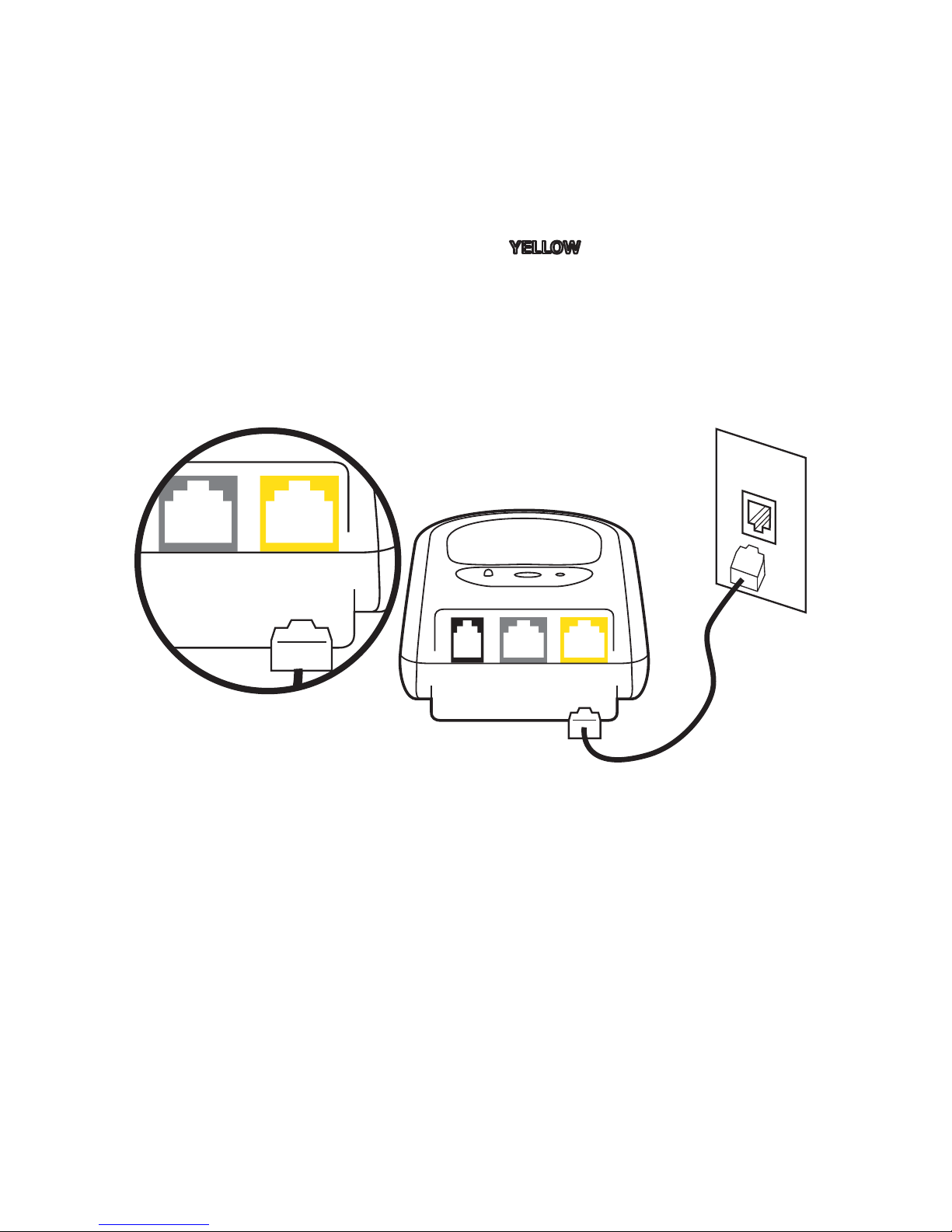
STEP 5
Plug the telephone cord (provided) into the jack on the back of the base
station marked PHONE LINE IN FROM WALL OUTLET. See Fig. 5
STEP 6
Plug the other end of the telephone cord into the telephone jack in the wall. See Fig. 6
STEP 6
Telephone
Cord
DC EXTRA
PHONE JACK
PHONE LINE
IN FROM
WALL OUTLET
Fig. 5
Fig. 6
3
YELLOWYELLOW

4
YOUR MediPendant™ SYSTEM IS NOW ACTIVATED AND READY FOR USE.
See OWNER’S MANUAL for further instructions.
STEP 7
Press and hold the LARGE ROUND GREY button for
3 seconds on the front of the pendant.
See Fig. 7
You will hear the pendant say, “Your emer-
gency call is now being dialed, please stand
by.” It will say this multiple times. The green
light on the pendant will illuminate indicating
that it has been activated and will remain illumi-
nated during the entire conversation with the
emergency operator.
See Fig. 7A
STEP 8
You will then hear a dial tone, followed by a dialing sequence. This is an indication
that your pendant is attempting to call the monitoring center.
When dialing sequence is completed, your pendant will again say, “Your emer-
gency call is now being dialed, please stand by.”
Soon after, there will be a brief period of silence. This means that your pendant is
talking to the monitoring center, and establishing communication.
Fig. 7
Fig. 7A
STEP 9
Wait a few moments to hear the operator’s voice through the pendant identifying
themselves and asking you if everything is OK.
STEP 10
Identify yourself with the operator and tell him/her that you are simply testing your
system. Follow the operator’s instructions to complete the test.
5215-CMilitiaHillRoad,PlymouthMeeting,PA 19462
www.MedicalAlarmConcepts.com
Manufactured by
TM
Rev. QSG01
08/09

5
¿Cómo instalar el MediPendant™?
Este manual es para la instalación básica de su MediPendant™. Por favor
lea el MANUAL DEL USUARIO para obtener instrucciones detalladas,
detalles del producto, garantías y renuncias.
Modelo #MED01
MediPendant™
PASO 1
Coloque la estación base del MediPendant™ en una superficie estable ubicada cerca de
una salida de corriente eléctrica y una salida de teléfono disponible. Para mejores
resultados, ubique la estación base lejos de artefactos eléctricos que pudieran presen-
tar interferencia eléctrica. Ver Fig. 1
Si usted posee más de un sistema MediPendant™ en su residencia, le recomendamos
que separe cada estación base con una distancia de al menos 15 pies
PASO 2
Tome la PAPELETA ROJA ubicada en la parte lateral de la estación base y hálela. Este
paso activa la batería de respaldo en caso de falla de la corriente eléctrica. Ver Fig. 2
La unidad emitirá continuamente un sonido “bip” y la luz de ALIMENTACIÓN DE
CORRIENTE (POWER) y la luz de indicación de la línea telefónica (PHONE LINE) se
encenderán de manera intermitente en rojo hasta que el adaptador de corriente
AC/DC sea conectado. Ver PASO 3.
Fig. 2
Fig. 1
Salida de
Teléfono
Salida de
Corriente
GUIA DE INICIO RÁPIDO
10 PASOS
6
PASO 3
Conecte el adaptador de corriente AC/DC dentro del enchufe NEGRO en la parte
posterior de la estación base marcada DC. Ver Fig. 3
PASO 4
Conecte el otro extremo del adaptador de corriente AC/DC dentro de la salida de
corriente de la pared. Ver Fig. 4
Una vez conectado, la base continuará emitiendo el sonido “bip” y la luz de la línea
telefónica (PHONE LINE) continuará encendida de forma intermitente de color rojo.
La luz de ALIMENTACIÓN DE CORRIENTE (POWER) cambiará de rojo intermitente
a verde continuo.
NOTA: NO CONECTE EL ADAPTADOR DE CORRIENTE AC/DC EN UNA SALIDA DE
CORRIENTE CONTROLADA POR UN INTERRUPTOR DE PARED. Si el interruptor se
apaga accidentalmente el sistema comenzará a sonar “bip” indicando la falta de
corriente eléctrica.
NOTA: Al faltar la corriente, la luz de ALIMENTACIÓN DE CORRIENTE (POWER)
ubicada en el centro en la parte superior de la estación base se encenderá intermi-
tentemente de color rojo y la unidad comenzará a emitir un sonido “bip” PARA SILEN-
CIAR CUALQUIER TONO DE LA ESTACIÓN BASE, simplemente presione el botón de
silencio (SILENT/SET UP) en la esquina superior derecha de la estación base.
DC EXTRA
PHONE JACK
PHONE LINE
IN FROM
WALL OUTLET
DC EXTRA TO
PHONE JACK
PHONE LINE
IN FROM
WALL OUTLET
PASO 3
PASO 4
Adaptador de
corriente AC/DC
Fig. 3
Fig. 4
Enchufe adicional
para Teléfono Línea de teléfono
desde la pared

7
SI USTED TIENE UN TELÉFONO ENCHUFADO EN LA SALIDA DE TELÉFONO DE LA
PARED, desconecte el cable de teléfono del enchufe de la pared y conéctelo en el
enchufe GRIS en la parte posterior de la estación base que indica ENCHUFE ADICIO-
NAL PARA TELÉFONO (EXTRA PHONE JACK). Continúe con los PASOS 5 y 6.
Si la operación fue realizada correctamente, la LUZ ROJA DE INDICACION DE LA
LINEA TELEFONICA (PHONE LINE) ubicada en la parte superior de la estación base
debe apagarse y el sonido “bip” dejará de sonar.
Si su sistema de telefonía es DSL o VoIP, por favor vea el MANUAL DEL USUARIO
DEL MediPendant™ para configuraciones opcionales del teléfono.
STEP 5
DC EXTRA
PHONE JACK
PHONE LINE
IN FROM
WALL OUTLET
PASO 5
Conecte el cable telefónico (suministrado) dentro del enchufe en la
parte posterior de la estación base que indica LINEA TELÉFONO DESDE LA
PARED (PHONE LINE IN FROM WALL OUTLET). Ver Fig. 5
PASO 6
Conecte el otro extremo del cable telefónico en la salida telefónica de la pared.
Ver Fig. 6
STEP 6
Cable de
Teléfono
DC EXTRA
PHONE JACK
PHONE LINE
IN FROM
WALL OUTLET
Fig. 5
Fig. 6
AMARILLOAMARILLO
Enchufe adicional
para Teléfono
Enchufe adicional
para Teléfono
Línea de teléfono
desde la pared
Línea de teléfono
desde la pared

8
SU SISTEMA MediPendant™ HA SIDO ACTIVADO Y ESTÁ LISTO PARA SER USADO.
Para mayor información, vea el MANUAL DEL USUARIO
PASO 7
Mantenga presionado el botón GRIS, GRANDE Y
REDONDO que se encuentra en la parte frontal del
pendiente por 3 segundos hasta que haga click.
Ver
Fig. 7
Usted escuchará al pendiente decir “Su llamada
de emergencia está siendo discada, por favor
espere” El pendiente repetirá esta frase continua-
mente. La luz verde del pendiente se encenderá
indicando que este ha sido activado y
permanecerá encendida durante toda la
conversación con el operador de emergencia.
Ver Fig. 7A
PASO 8
Usted escuchará el tono de discado seguido por una secuencia de discado. Esto le
indica que su pendiente está llamando al centro de monitoreo de llamadas de emer-
gencia.
Cuando la secuencia de discado se complete, su pendiente repetirá nuevamente
“Su llamada de emergencia está siendo discada, por favor espere”
Inmediatamente después habrá un período de silencio; esto significa que el pendiente
se está comunicando con el centro de monitoreo de llamadas de emergencia.
Fig. 7
Fig. 7A
PASO 9
Espere algunos segundos para escuchar al operador a través del pendiente identi-
ficándose y preguntándole si todo se encuentra BIEN.
PASO 10
Identifíquese con el operador e indíquele que usted se encuentra probando su sistema.
Siga las instrucciones del operador para completar la prueba.
5215-CMilitiaHillRoad,PlymouthMeeting,PA 19462
www.MedicalAlarmConcepts.com
Fabricado por
TM
Table of contents
Languages:
Popular Emergency Phone manuals by other brands


Linear
Linear PERS-4200 Series quick guide

Rath
Rath 2100-986GSM Installation & operation manual

Rath
Rath 2100-PLL Landline 12v Pedestal Installation & operation manual

Disty
Disty distyNotruf stationar operating instructions

Aiphone
Aiphone NEM-10 instructions
LogicMark
LogicMark CaretakerSentry Quick install guide

SPOT
SPOT Satellite GPS Messenger user guide

Alpha Communications
Alpha Communications AlphaRefuge 2100 Series Installation, Use and Wiring Instructions

TeleAlarm
TeleAlarm Carephone 62 Quick user guide

LifeWatch
LifeWatch Emergency Phone Quick setup guide

basIP
basIP AV-04AFD user manual

LogicMark
LogicMark 37911 Set-up & operating instructions