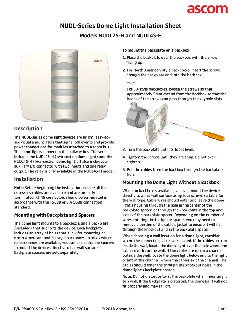
ASCOM NICL4 User manual

INSTALLATION GUIDE
Corridor Lamp 4

INSTALLATION GUIDE
Corridor Lamp 4
Contents
1 Symbols — NICL4 Install Sheet ........................................................................................................ 1
2 Descri tion....................................................................................................................................2
3 Installation.....................................................................................................................................3
4 Im ortant Safety Information ..........................................................................................................4
5 Mounting.......................................................................................................................................5
5.1 Mount the NICL4 base onto a backbox..................................................................................5
5.2 Mount the Base without a Backbox.......................................................................................6
6 Connections and DIP Switch Settings..............................................................................................8
7 Setting the Corridor Lam ID......................................................................................................... 10
8 Terminating and Mounting the Room Bus RJ45 Connectors ............................................................ 11
9 NILDx LED Lam Placement ......................................................................................................... 13
TD 93352EN / 25 January 2021 / Ver. A

INSTALLATION GUIDE
Corridor Lamp 4 Symbols — NICL4 Install Sheet
1 Symbols — NICL4 Install Sheet
Read the manual for more information
Caution: Use extreme caution and follow instructions carefully.
Caution: Bright LEDs behind translucent dome cover. High brightness light is produced
by the LED boards that are placed onto the NICL4 circuit board. Do not stare into the
light when the translucent dome cover is removed.
TD 93352EN / 25 January 2021 / Ver. A 1

Description
INSTALLATION GUIDE
Corridor Lamp 4
2 Descri tion
The Corridor Lamp (NICL4) is controlled by the room controller (NIRC4 only). Each room bus of the room
controller (NIRC4) can support up to four NICL4 corridor lamps.
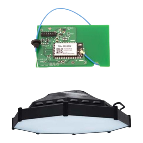
The NICL4 corridor lamp supports up to 4 LED boards (NILD2, NILD4–RGB) behind a translucent dome
cover.
The NICL4 is connected to the room bus with an RJ45 cable using the Ethernet standard (T-568B) color
coding. The corridor lamp has two RJ45 room bus connectors for daisy chaining with the NU-series
peripheral devices (PDs).
The input power (5.5VDC) of the corridor lamp is supplied through the room bus connection.
2TD 93352EN / 25 January 2021 / Ver. A

INSTALLATION GUIDE
Corridor Lamp 4 Installation
3 Installation
The NICL4 has an IP40 ingress protection. The areas in which NICL4s are to be installed must be clean, dry,
and weatherproof. The walls on which devices are to be installed should be finished (painted, wall papered,
etc.) before the devices are installed. It is important to have the appropriate length of free cable available at
every location where the NICL4 is to be installed.
TD 93352EN / 25 January 2021 / Ver. A 3

Important Safety Information
INSTALLATION GUIDE
Corridor Lamp 4
4 Im ortant Safety Information
The Corridor Lamp 4 (NICL4) Installation Instructions contain important instructions for use during installa-
tion and maintenance of the NICL4. To ensure a safe working environment during the installation and
operation of the NICL4, the following safety symbols appear throughout this document to indicate
dangerous conditions and important safety instructions.
Caution: Use extreme caution and follow instructions carefully.
4TD 93352EN / 25 January 2021 / Ver. A

INSTALLATION GUIDE
Corridor Lamp 4 Mounting
5 Mounting
The base of the NICL4 mounts to backboxes using an array of holes that allow for mounting on various EU
and North American-style backboxes. In areas where no backboxes are available, the base can be mounted
directly onto flat wall surfaces.
Caution: To prevent a fire hazard because of dust buildup inside the NICL4, regular
inspection and/or cleaning of the NICL4 is required.
Caution: Take proper measures to avoid spreading dust and other particles when applying
maintenance to an NICL4 that is mounted inside a clinical area.
5.1 Mount the NICL4 base onto a backbox
1. Place the base over the backbox with the spring type holding clip pointing to the left.
2. For EU-style backboxes, loosen the screws so that approximately 5mm extend from the backbox so
that the heads of the screws can pass through the key-hole slots.
For North American-style backboxes, insert the screws (included) though the backplate and into the 2-
gang backbox.
3. Position the base until its top is level.
4. Tighten the screws until they are snug. Do not overtighten.
5. Pull the cables from the backbox through the base hole.
TD 93352EN / 25 January 2021 / Ver. A 5

Mounting
INSTALLATION GUIDE
Corridor Lamp 4
5.2 Mount the Base without a Backbox
When mounting the NICL4 on a drywall without a backbox, mount the base of the NICL4 directly to a flat
wall surface using four screws suitable for the wall type.
Cable wires should enter and leave the device’s housing through the hole in the center of the base, or
through the knockouts at the bottom or right side of the base. Depending on the number of wires entering
the base, you may need to remove a portion of the cable’s jacket to ensure it will fit though the knockout.
When choosing a wall location for an NICL4, consider where the connecting cables are located. If the
connecting cables are run inside the wall, locate the base of the NICL4 over the hole where the cables exit
from the wall. If the connecting cables are run in a channel outside the wall, locate the base above or to the
left of the channel, where the cables exit the channel. The cables should enter through the knockout holes
in the base of the NICL4.
Do not distort or twist the base when mounting it to a wall. If the base is distorted, the NICL4 dome
cover will not fit properly and may fall off.
Figure 1. NICL4 Base Orientation and Cutouts
Legend
1. Arrow indicator
2. Spring type holding clip
3. Cutouts
To remove the knockouts
1. Locate the knockouts to be removed from the bottom or right side of the base. See Figure 1. NICL4
Base Orientation and Cutouts, page 6, items 3.
6TD 93352EN / 25 January 2021 / Ver. A

INSTALLATION GUIDE
Corridor Lamp 4 Mounting
2. Using a cutter or pliers, carefully remove the excess plastic from the knockouts.
To mount the NICL4 base on a wall
1. Place the base against a flat wall and orient it so that arrow is pointing up and that the base is level.
(See Figure 1. NICL4 Base Orientation and Cutouts, page 6, item 1.) Use a leveling device to check, if
necessary.
2. Make sure that the knockouts are pointing down and to the right. (See Figure 1. NICL4 Base Orientation
and Cutouts, page 6, items 3.)
3. Using the base as a template, mark four holes for the screws using the slotted fitting holes located in
the base.
4. Remove the base spacer and drill holes for the screws that will be used, such as wood, concrete, or
drywall screws, or screws with anchors.
5. Place the base (with the knockouts removed) over the holes, insert the screws, and then tighten.
6. Pull the cables through the knockout holes and follow the directions in the following sections.
Caution: The NICL4 must be mounted in a way that the module is firmly attached to the
background.
TD 93352EN / 25 January 2021 / Ver. A 7

Connections and DIP Switch Settings
INSTALLATION GUIDE
Corridor Lamp 4
6 Connections and DIP Switch Settings
Before attaching the PCB to its base, make all wire connections and DIP switch settings. Be sure that
required cables are properly connected. The following figures show the locations for each cable.
Figure 2. NICL4 Circuit Board - Front
Legend
(1) LED lamp (NILD2, NILD4–RGB) connections
8TD 93352EN / 25 January 2021 / Ver. A

INSTALLATION GUIDE
Corridor Lamp 4 Connections and DIP Switch Settings
Figure 3. NICL4 Circuit Board - Back
Legend
(1) DIP switches for Corridor Lamp ID selection
(2) Buzzer
(3) RJ45 room bus connectors for connection to NIRC4 room controller and NU-series PDs via daisy
chaining
TD 93352EN / 25 January 2021 / Ver. A 9

Setting the Corridor Lamp ID
INSTALLATION GUIDE
Corridor Lamp 4
7 Setting the Corridor Lam ID
Before connecting any of the wires, first set the corridor lamp ID selection DIP switch. Up to four corridor
lamps (NICL4 only) can be connected to each room bus of the room controller (NIRC4 only). The following
figure illustrates the DIP switch found on the back of a NICL4 circuit board.
Figure 4. Corridor Lamp ID Selection DIP Switch
The following table shows the DIP switch settings for all IDs.
DIP switch settings for corridor lam ID selection
To set a DIP switch:
1. Set the DIP switches to the ID (0 to 3) chosen for the NICL4. Use the ID table above to determine the
correct positions (ON or OFF) for the DIP switches.
2. Using a small screwdriver, gently slide the switch up for “ON” or slide it down for “OFF.”
10 TD 93352EN / 25 January 2021 / Ver. A

INSTALLATION GUIDE
Corridor Lamp 4 Terminating and Mounting the Room Bus RJ45 Connectors
8 Terminating and Mounting the Room Bus RJ45 Connectors
The NICL4 includes two active room bus RJ45 sockets. Crimp the RJ45 connector(s) to the room bus cable
(s) using the Ethernet T-568B termination color scheme. The following figure shows the correct pinout for
terminating the active room bus cables.
RJ45 connector for active room bus cable
For easy mounting of the RJ45 connector, use Easy RJ45 connectors that allow feeding excess wire length
through the connector. When crimping, the excess wire length will be cut automatically.
(Easy) RJ45 connectors are not included and must be ordered separately.
Easy RJ45 connectors require a dedicated crimping tool that includes a cutting mechanism to cut
the excess wire when crimping the connector on the cable.
To mount the RJ45 room bus connectors:
1. Ensure the active room bus cables are properly terminated with an RJ45 connector.
2. Plug the RJ45 connector into one of the RJ45 sockets on the NICL4 circuit board. When daisy chaining
the room bus from one peripheral device to the other, both RJ45 sockets will be used.
TD 93352EN / 25 January 2021 / Ver. A 11

INSTALLATION GUIDE
Corridor Lamp 4 NILDx LED Lamp Placement
9 NILDx LED Lam Placement
A corridor lamp supports up to 4 NILD2 or NILD4-RGB LED boards.
NILDx LED boards are not included and must be ordered separately.
Caution: Bright LEDs behind translucent dome cover. High brightness light is produced by
the LED boards that are placed onto the NICL4 circuit board. Do not stare into the light when
the translucent dome cover is removed.
To lace the NILDx LED board(s):
1. Insert the LED boards into the NICL4. The pins on the LED lamp board are not in the centre of the
board, therefore it is important to make sure that the LED lamp board lines up with the guide marks on
the corridor lamp PCB when the pins are inserted.
The LED lamp connection points are labelled LED0, LED1, LED2 and LED3. Any color LED
board (NILD2) or multi color LED board (NILD4-RGB) can be plugged into any of the
connection points in the corridor lamp. The appropriate position of the LED color is
determined during the system setup.
2. With the three pins inserted and the LED lamp board lined up with the guide marks, press the LED lamp
board flat onto the corridor lamp PCB. Repeat the procedure on the other required LED lamp boards.
Figure 6. Insert LED Boards
TD 93352EN / 25 January 2021 / Ver. A 13

Ascom (Sweden) AB
Grimbodalen 2
SE–417 49 Göteborg
Sweden
Phone +46 31 55 93 00
www.ascom.com
TD 93352EN / 25 January 2021 / Ver. A
last page
Table of contents
Other ASCOM Lighting Equipment manuals
Popular Lighting Equipment manuals by other brands

HYBRYD
HYBRYD CRYSTAL LED Installation and maintenance manual
CoeLux
CoeLux HT25 Installation and user manual

NEO
NEO STORMER 1200 IP user manual

CentoLight
CentoLight Moodliner 1812WP user manual

Panasonic
Panasonic SF4B C Series instruction manual

Philips
Philips GreenPower TLED InstantFit Quick installation guide
VisioPool
VisioPool Gre 770270 installation instructions

American DJ
American DJ Laser Widow owner's manual

Clevertronics
Clevertronics LP CSBLED Series Installation & maintenance instructions
Lightolier
Lightolier Lytespan 8707E specification

Gemmy
Gemmy 11955 instructions

COMPLED Solutions GmbH
COMPLED Solutions GmbH HashCropter user manual

