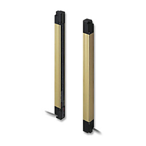
Panasonic SF4B C Series User manual

2023.6 panasonic.net/id/pidsx/global
Compact Light Curtain / Type 4
6)%Ƒ&Ƒ
Instruction Manual
WUME-SF4BC-11

© Panasonic Industrial Devices SUNX Co., Ltd. 20232
(MEMO)

© Panasonic Industrial Devices SUNX Co., Ltd. 2023 3
Thank you for purchasing Panasonic Industrial Devices SUNX’s Compact Light Curtain, SF4B-Ƒ&Ƒ
Please read this instruction manual carefully and thoroughly for the correct and optimum use of
WKLVGHYLFH
.LQGO\NHHSWKLVPDQXDOLQDFRQYHQLHQWSODFHIRUTXLFNUHIHUHQFH
This device is a light curtain for protecting a person from dangerous parts of a machine which
FDQFDXVHLQMXU\RUDFFLGHQW
This manual is for the following personnel:
who have undergone suitable training,
who have knowledge of the light curtains as well as the safety systems and the standards,
Ɣwho are responsible for the introduction of this device,
Ɣwho design the system using this device,
Ɣwho install and connect this device,
Ɣ ZKRPDQDJHDQGRSHUDWHDSODQWXVLQJWKLVGHYLFH
Notes
1) All the contents of this instruction manual are the copyright of the publishers, and may not
be reproduced (even extracts) in any form by any electronic or mechanical means (including
photocopying, recording, or information storage and retrieval) without permission in writing
IURPWKHSXEOLVKHU
2) The contents of this instruction manual may be changed without prior notice for further im-
SURYHPHQWRIWKHGHYLFH
3)
Though we have carefully drawn up the contents of this instruction manual, if there are any as-
pects that are not clear, or any error that you may notice, please contact our local Panasonic
,QGXVWULDO'HYLFHV681;RႈFHRIWKHQHDUHVWGLVWULEXWRU
(QJOLVKDQG-DSDQHVHDUHRULJLQDOLQVWUXFWLRQV

© Panasonic Industrial Devices SUNX Co., Ltd. 20234
&RQWHQWV
Chapter 1 Introduction ······································································· 6
1-1 Attention Marks ············································································6
1-2 Safety Precautions ········································································6
1-3 Applicable Standards / Regulations ··················································9
&RQ¿UPDWLRQRI3DFNHG&RQWHQWV ··················································· 10
Chapter 2 Before Using This Device ····················································11
2-1 Features ··················································································· 11
2-2 Part Description·········································································· 11
2-3 Protection Area ·········································································· 14
2-3-1 Sensing Area ········································································14
2-3-2 Safety Distance ·····································································15
,QÀXHQFHRI5HÀHFWLYH6XUIDFHV ················································19
2-3-4 Device Placement ··································································20
2-4 Mounting··················································································· 22
2-4-1 Mounting of the Mounting Bracket ·············································22
2-5 Wiring······················································································· 36
2-5-1 Power Supply Unit··································································36
2-5-2 I/O Circuit Diagrams and Output Waveform ·································37
2-5-3 Wiring · Connecting Procedure and Connector Pin Arrangement ·····43
2-5-4 Basic Wiring··········································································45
2-5-5 Wiring for Manual Reset (Interlock is Valid) ·································49
2-5-6 Wiring for Auto-reset (Interlock is Invalid) ····································53
:LULQJ&RQ¿JXUDWLRQIRU,QYDOLG([WHUQDO'HYLFH0RQLWRU)XQFWLRQ ····57
:LULQJ&RQ¿JXUDWLRQIRU9DOLG0XWLQJ)XQFWLRQ)RU6)%Ƒ&$- only)
···61
2-6 Adjustment ················································································ 63
2-6-1 Beam-axis Alignment ······························································63
2-6-2 Operation Test ······································································65
2-6-3 Operation ·············································································66
Chapter 3 Functions·········································································71
3-1 Self-diagnosis Function ································································ 71
3-2 Interlock Function ······································································· 71
3-3 Emission Halt Function ································································ 72
3-4 Auxiliary Output (Non-safety Output)··············································· 73
3-5 External Device Monitor Function ··················································· 73
3-6 Muting Function (For 6)%Ƒ&$- only) ······································ 75
3-7 Override Function (For 6)%Ƒ&$- only) ···································· 78
3-8 Functions Using Handy Controller (6)%+&) (Optional) ······················ 80
Chapter 4 Maintenance·····································································83
4-1 Daily Inspection ·········································································· 83
4-2 Periodic Inspection (Every Six Months)············································ 84
4-3 Inspection after Maintenance························································· 84

© Panasonic Industrial Devices SUNX Co., Ltd. 2023 5
Chapter 5 Troubleshooting ································································85
5-1 Troubleshooting of Emitter ···························································· 85
5-2 Troubleshooting of Receiver·························································· 87
&KDSWHU6SHFL¿FDWLRQV'LPHQVLRQV ·················································89
6SHFL¿FDWLRQV············································································· 89
6-2 Options····················································································· 96
6-3 Dimensions················································································ 99
6-3-1 Rear Mounting with 066)%& and 066)%&·····················99
6-3-2 Side Mounting with 066)%& and 066)%& ··················· 100
6-3-3 Rear Mounting with 066)%& and 066)%&··················· 101
,Q&DVH0RXQWLQJLQ&RQ¿QHG6SDFHZLWK066)%& and 066)%&
··· 102
6-3-5 Side Mounting with 066)%& and 066)%& ··················· 103
,Q&DVH0RXQWLQJLQ&RQ¿QHG6SDFHZLWK066)%& and 066)%&
··· 104
6-3-7 Mounting with 066)%& and 066)%& ·························· 105
,Q&DVH0RXQWLQJLQ&RQ¿QHG6SDFHZLWK066)%& and 066)%&
··· 106
6-3-9 Mounting with 066)%&+Ƒ and 066)%&························ 107
6-3-10 Mounting Brackets······························································ 108
Chapter 7 Others··········································································· 119
7-1 Glossary ················································································· 119
7-2 CE Marking Declaration of Conformity··········································· 120
7-3 UKCA Marking Declaration of Conformity······································· 121

© Panasonic Industrial Devices SUNX Co., Ltd. 20236
&KDSWHU,QWURGXFWLRQ
$WWHQWLRQ0DUNV
This instruction manual employs the following attentions marks “ :$51,1*,” “ &$87,21”
GHSHQGLQJRQWKHGHJUHHRIWKHGDQJHUWRFDOORSHUDWRU¶VDWWHQWLRQWRHDFKSDUWLFXODUDFWLRQ
Read the following explanation of these marks thoroughly and observe these notices without
IDLO
:$51,1* ,I\RXLJQRUHWKHDGYLFHZLWKWKLVPDUNGHDWKRUVHULRXVLQMXU\FRXOGUHVXOW
&$87,21 ,I\RXLJQRUHWKHDGYLFHZLWKWKLVPDUNLQMXU\RUPDWHULDOGDPDJHFRXOGUHVXOW
5HIHUHQFH! ,WJLYHVXVHIXOLQIRUPDWLRQIRUEHWWHUXVHRIWKLVGHYLFH
6DIHW\3UHFDXWLRQV
Ŷ 8VHWKLVGHYLFHDVSHULWVVSHFL¿FDWLRQV'RQRWPRGLI\WKLVGHYLFHVLQFHLWVIXQFWLRQVDQGFD-
SDELOLWLHVPD\QRWEHPDLQWDLQHGDQGLWPD\PDOIXQFWLRQ
Ŷ 7KLVGHYLFHKDVEHHQGHYHORSHGSURGXFHGIRULQGXVWULDOXVHRQO\
Ŷ 7KLVGHYLFHLVVXLWDEOHIRULQGRRUXVHRQO\
Ŷ 8VHRIWKLVGHYLFHXQGHUWKHIROORZLQJFRQGLWLRQVRUHQYLURQPHQWVLVQRWSUHVXSSRVHG3OHDVH
FRQVXOWXVLIWKHUHLVQRRWKHUFKRLFHEXWWRXVHWKLVGHYLFHLQVXFKDQHQYLURQPHQW
2SHUDWLQJWKLVGHYLFHXQGHUFRQGLWLRQVRUHQYLURQPHQWVQRWGHVFULEHGLQWKLVPDQXDO
2) Using this device in the following fields: nuclear power control, railroad, aircraft, auto
PRELOHVFRPEXVWLRQIDFLOLWLHVPHGLFDOV\VWHPVDHURVSDFHGHYHORSPHQWHWF
ŶWhen this device is to be used for enforcing protection of a person from any danger occurring
around an operating machine, the user should satisfy the regulations established by national
or regional security committees (Occupational Safety and Health Administration: OSHA, the
(XURSHDQ6WDQGDUGL]DWLRQ&RPPLWWHHHWF&RQWDFWWKHUHODWLYHRUJDQL]DWLRQVIRUGHWDLOV
ŶIn case of installing this device to a particular machine, follow the safety regulations in regard
WRDSSURSULDWHXVDJHPRXQWLQJLQVWDOODWLRQRSHUDWLRQDQGPDLQWHQDQFH7KHXVHUVLQFOXG-
LQJWKHLQVWDOODWLRQRSHUDWRUDUHUHVSRQVLEOHIRUWKHLQWURGXFWLRQRIWKLVGHYLFH
ŶNote that this device may be damaged if it is subject to a strong shock (if it is dropped onto
WKHÀRRUIRUH[DPSOH
ŶUse this device by installing suitable protection equipment as a countermeasure for failure,
GDPDJHRUPDOIXQFWLRQRIWKLVGHYLFH
ŶBefore using this device, check whether the device performs properly with the functions and
FDSDELOLWLHVDVSHUWKHGHVLJQVSHFL¿FDWLRQV
Ŷ ,QFDVHRIGLVSRVDOGLVSRVHWKLVGHYLFHDVDQLQGXVWULDOZDVWH
Ŷ 'RQRWXVHWKLVSURGXFWZLWKPRELOHHTXLSPHQWVXFKDVDQDXWRPDWHGJXLGHGYHKLFOH$*9

© Panasonic Industrial Devices SUNX Co., Ltd. 2023 7
,QWURGXFWLRQ
:$51,1*
Ƈ0DFKLQHGHVLJQHULQVWDOOHUHPSOR\HUDQGRSHUDWRU
ƔThe machine designer, installer, employer and operator are solely responsible to ensure
that all applicable legal requirements relating to the installation and the use in any appli-
FDWLRQDUHVDWLV¿HGDQGDOOLQVWUXFWLRQVIRULQVWDOODWLRQDQGPDLQWHQDQFHFRQWDLQHGLQWKH
LQVWUXFWLRQPDQXDODUHIROORZHG
ƔWhether this device functions as intended to and systems including this device comply
with safety regulations depends on the appropriateness of the application, installation,
PDLQWHQDQFHDQGRSHUDWLRQ7KHPDFKLQHGHVLJQHULQVWDOOHUHPSOR\HUDQGRSHUDWRUDUH
VROHO\UHVSRQVLEOHIRUWKHVHLWHPV
Ƈ(QJLQHHU
ƔThe engineer would be a person who is appropriately educated, has widespread knowl-
edge and experience, and can solve various problems which may arise during work, such
DVDPDFKLQHGHVLJQHURUDSHUVRQLQFKDUJHRILQVWDOODWLRQRURSHUDWLRQHWF
Ƈ2SHUDWRU
ƔThe operator should read this instruction manual thoroughly, understand its contents, and
perform operations following the procedures described in this manual for the correct op-
HUDWLRQRIWKLVGHYLFH
ƔIn case this device does not perform properly, the operator should report this to the person
LQFKDUJHDQGVWRSWKHPDFKLQHRSHUDWLRQLPPHGLDWHO\7KHPDFKLQHPXVWQRWEHRSHU-
DWHGXQWLOFRUUHFWSHUIRUPDQFHRIWKLVGHYLFHKDVEHHQFRQ¿UPHG
Ƈ(QYLURQPHQW
Ɣ 'RQRWXVHDPRELOHSKRQHRUDUDGLRSKRQHQHDUWKLVGHYLFH
Ɣ ,IWKHUHH[LVWVDUHÀHFWLYHVXUIDFHLQWKHSODFHZKHUHWKLVGHYLFHLVWREHLQVWDOOHGPDNH
VXUHWRLQVWDOOWKLVGHYLFHVRWKDWUHÀHFWHGOLJKWIURPWKHUHÀHFWLYHVXUIDFHGRHVQRWHQWHU
into the receiver, or take countermeasures such as painting, masking, roughening, or
FKDQJLQJWKHPDWHULDORIWKHUHÀHFWLYHVXUIDFHHWF)DLOXUHWRGRVRPD\FDXVHWKHGHYLFH
QRWWRGHWHFWUHVXOWLQJLQGHDWKRUVHULRXVLQMXU\
Ɣ 'RQRWLQVWDOOWKLVGHYLFHLQWKHIROORZLQJHQYLURQPHQWV
1)
$UHDVH[SRVHGWRLQWHQVHLQWHUIHUHQFHH[WUDQHRXVOLJKWVXFKDVKLJKIUHTXHQF\ÀXRUHVFHQW
ODPSLQYHUWHUW\SHUDSLGVWDUWHUÀXRUHVFHQWODPSVWURERVFRSLFOLJKWVRUGLUHFWVXQOLJKW
2) Areas with high humidity where condensation is likely to occur
3) Areas exposed to corrosive or explosive gases
$UHDVH[SRVHGWRYLEUDWLRQRUVKRFNRIOHYHOVKLJKHUWKDQWKDWVSHFL¿HG
5) Areas exposed to contact with water
6) Areas exposed to too much steam or dust
Ƈ,QVWDOODWLRQ
ƔAlways keep the correctly calculated safety distance between this device and the danger-
RXVSDUWVRIWKHPDFKLQH
ƔInstall extra protection structure around the machine so that the operator must pass
WKURXJKWKHVHQVLQJDUHDRIWKLVGHYLFHWRUHDFKWKHGDQJHURXVSDUWVRIWKHPDFKLQH
ƔInstall this device such that some part of the operator’s body always remains in the sens-
LQJDUHDZKHQRSHUDWRULVGRQHZLWKWKHGDQJHURXVSDUWVRIWKHPDFKLQH
Ɣ 'RQRWLQVWDOOWKLVGHYLFHDWDORFDWLRQZKHUHLWFDQEHDႇHFWHGE\ZDOOUHÀHFWLRQ
ƔWhen installing multiple sets of this device, connect the sets and, if necessary, install some barri-
HUVVXFKWKDWPXWXDOLQWHUIHUHQFHGRHVQRWRFFXU)RUGHWDLOVUHIHUWR³'HYLFH3ODFHPHQW´
Ɣ 'RQRWXVHWKLVGHYLFHLQDUHÀHFWLYHFRQ¿JXUDWLRQ
Ɣ 7KHFRUUHVSRQGLQJHPLWWHUDQGUHFHLYHUPXVWKDYHWKHVDPHVHULDO1RDQGEHFRUUHFWO\
RULHQWHG

© Panasonic Industrial Devices SUNX Co., Ltd. 20238
,QWURGXFWLRQ
:$51,1*
Ƈ0DFKLQHLQZKLFKWKLVGHYLFHLVLQVWDOOHG
Ɣ :KHQWKLVGHYLFHLVXVHGLQWKH³36',0RGH´DQDSSURSULDWHFRQWUROFLUFXLWPXVWEHFRQ¿J-
XUHGEHWZHHQWKLVGHYLFHDQGWKHPDFKLQHU\)RUGHWDLOVEHVXUHWRUHIHUWRWKHVWDQGDUGV
RUUHJXODWLRQVDSSOLFDEOHLQHDFKUHJLRQRUFRXQWU\
ƔIn Japan and China, Korea, do not use this device as safety equipment for a press ma-
FKLQH
ƔDo not install this device with a machine whose operation cannot be stopped immediately
LQWKHPLGGOHRIDQRSHUDWLRQF\FOHE\DQHPHUJHQF\VWRSHTXLSPHQW
Ɣ 7KLVGHYLFHVWDUWVWKHSHUIRUPDQFHDIWHUVHFRQGVIURPWKHSRZHU21+DYHWKHFRQWURO
V\VWHPVWDUWHGWRIXQFWLRQZLWKWKLVWLPLQJ
Ƈ:LULQJ
Ɣ %HVXUHWRFDUU\RXWWKHZLULQJLQWKHSRZHUVXSSO\2))FRQGLWLRQ
Ɣ $OOHOHFWULFDOZLULQJVKRXOGFRQIRUPWRWKHUHJLRQDOHOHFWULFDOUHJXODWLRQVDQGODZV7KHZLU-
LQJVKRXOGEHGRQHE\HQJLQHHUVKDYLQJWKHVSHFLDOHOHFWULFDONQRZOHGJH
ƔDo not run the wires together with high-voltage lines or power lines or put them in the
VDPHUDFHZD\7KLVFDQFDXVHPDOIXQFWLRQGXHWRLQGXFWLRQ
ƔIn case of extending the cable of the emitter or the receiver, each can be extended up to
PE\XVLQJWKHH[FOXVLYHFDEOH([WHQGLQJWKHFDEOHORQJHUWKDQPPD\FDXVHPDO-
IXQFWLRQZKLFKFDQUHVXOWLQGHDWKRUVHULRXVLQMXU\
Ɣ 'RQRWFRQWUROWKHGHYLFHRQO\DWRQHFRQWURORXWSXW266'
ƔIn order that the output is not turned to ON due to earth fault of the control output (OSSD 1
ZLUHVEHVXUHWRJURXQGWR9VLGH313RXWSXW9VLGH131RXWSXW
Ɣ :KHQXVLQJWKLVGHYLFHLQ.RUHDZLWK6PDUNEHVXUHWRJURXQGWR9VLGH313RXWSXW
Ƈ0DLQWHQDQFH
ƔWhen replacement parts are required, always use only genuine supplied replacement
SDUWV,IVXEVWLWXWHSDUWVIURPDQRWKHUPDQXIDFWXUHUDUHXVHGWKHGHYLFHPD\QRWFRPHWR
GHWHFWUHVXOWLQGHDWKRUVHULRXVLQMXU\
ƔThe periodical inspection of this device must be performed by an engineer having the spe-
FLDONQRZOHGJH
ƔAfter maintenance or adjustment, and before starting operation, test this device following
WKHSURFHGXUHVSHFL¿HGLQ³&KDSWHU0DLQWHQDQFH´
Ɣ &OHDQWKLVGHYLFHZLWKDFOHDQFORWK'RQRWXVHDQ\YRODWLOHFKHPLFDOV
Ƈ2WKHUV
Ɣ 1HYHUPRGLI\WKLVGHYLFH0RGLILFDWLRQPD\FDXVHWKHGHYLFHQRWWRGHWHFWUHVXOWLQJLQ
GHDWKRUVHULRXVLQMXU\
Ɣ 'RQRWXVHWKLVGHYLFHWRGHWHFWREMHFWVÀ\LQJRYHUWKHVHQVLQJDUHD
ƔDo not use this device to detect transparent objects, translucent objects or objects smaller
WKDQWKHVSHFL¿HGPLQLPXPVHQVLQJREMHFWV

© Panasonic Industrial Devices SUNX Co., Ltd. 2023 9
,QWURGXFWLRQ
$SSOLFDEOH6WDQGDUGV5HJXODWLRQV
7KLVGHYLFHFRPSOLHVZLWKWKHIROORZLQJVWDQGDUGVUHJXODWLRQV
<$SSOLFDEOH'LUHFWLYHV$SSOLFDEOH5HJXODWLRQV!
EU Directives:Machinery Directive2006/42/EC
EMC Directives 2014/30/EU
RoHS Directives 2011/65/EU
British Legislation:Machinery Regulation 2008/1597
EMC Regulation 2016/1091
RoHS Regulation 2012/3032
$SSOLFDEOH6WDQGDUGV
EN ISO 13849-1:2015(Category 4, PLe), EN 55011, EN 61000-6-2, EN IEC 63000
IEC 61496-1:2020(Type 4), IEC 61496-2:2020(Type 4), IEC 61508-1 㹼7(SIL3)
865HJXODWLRQV:26+$, 26+$&, $16,% 㹼%, $16,5,$
<&RQIRUPLQJ6WDQGDUGV!
86&DQDGD6WDQGDUGVANSI/UL 61496-1/2(Type 4), ANSI/UL 508
&$1&6$&1R, CAN/CSA E61496-1/2(Type 4)
2WKHU6WDQGDUGVJIS B 9704-1/2(Type 4), JIS B 9705-1(Category 4), JIS C 0508(SIL3)
ISO 13849-1 : 2015(Category 4, PLe)
5HJDUGLQJ(80DFKLQHU\'LUHFWLYHD1RWL¿HG%RG\7h96h'KDVFHUWL¿HGZLWKWKHW\SHH[-
DPLQDWLRQFHUWL¿FDWH
:LWKUHJDUGWRWKHVWDQGDUGVLQ86&DQDGDD157/7h96h'KDVFHUWL¿HGIRUC7h9US0DUN
5HJXODWLRQVLQ.RUHD!
S1-G-35-2005, S2-W-11-2003
7KH6PDUNFHUWL¿FDWHKDVEHHQFHUWL¿HGE\.RUHD2FFXSDWLRQDO6DIHW\+HDOWK$JHQF\.26+$
5HIHUHQFH!
7KHFRQIRUPLW\WR-,626+$DQG$16,IRUWKLVGHYLFHKDVEHHQHYDOXDWHGE\RXUVHOYHV
The C7h9US mark “ ´LQGLFDWHVWKDWWKLVGHYLFHFRQIRUPVWR157/FHUWL¿FDWLRQVXFKDV8/LQ
WKH86DQG&6$FHUWL¿FDWLRQLQ&DQDGD
7KLVGHYLFHFRQIRUPVWRWKH(0&'LUHFWLYHDQGWKH0DFKLQHU\'LUHFWLYH7KH mark on the
PDLQERG\LQGLFDWHVWKDWWKLVGHYLFHFRQIRUPVWRWKH(0&'LUHFWLYH
7KLVGHYLFHFRQIRUPVWRWKH(0&5HJXODWLRQVDQGWKH0DFKLQHU\'LUHFWLYH7KH mark on the
PDLQERG\LQGLFDWHVWKDWWKLVGHYLFHFRQIRUPVWRWKH(0&5HJXODWLRQV
PDUNPDUNHGRQWKLVGHYLFHVKRZVWKDWWKLVGHYLFHKDVFHUWL¿HGZLWKWKHW\SHH[DPLQDWLRQFHU-
WL¿FDWH
:$51,1*
ƔIn Japan, never use this device as a safety equipment for any press machine or shearing ma-
FKLQH
Ɣ :KHQWKLVGHYLFHLVXVHGLQDSODFHRWKHUWKDQWKHSODFHVVKRZQDERYHEHVXUHWRFRQ¿UPWKH
VWDQGDUGVRUUHJXODWLRQVDSSOLFDEOHLQHDFKUHJLRQRUFRXQWU\EHIRUHXVH

© Panasonic Industrial Devices SUNX Co., Ltd. 202310
,QWURGXFWLRQ
%HIRUHWKHXVHRIWKLVGHYLFHFRQVWUXFWWKHFRQWUROV\VWHPWKDWVDWLV¿HVWKHIROORZLQJUHTXLUHPHQWV
WRVHFXUHWKHVDIHW\RIWKHZKROHV\VWHP
7RXVHIRU&DWHJRU\RU
Ɣ7RSUHYHQWWKHORVVRIWKHVDIHW\IXQFWLRQGXHWRDVLQJOHIDXOW
$OZD\VXVHWZRW\SHVRIFRQWURORXWSXW266'
Ɣ7RSUHYHQWWKHORVVRIWKHVDIHW\IXQFWLRQGXHWRWKHDFFXPXODWLRQRIWKHIDXOWV
Construct the control system that can stop a device if discrepancy between control outputs
266'LVGHWHFWHG
7KHH[DPSOHRIWKHZD\WRGHWHFWWKHGLVFUHSDQF\RIFRQWURORXWSXWV!
([DPSOH8VHWKHUHOD\XQLWRUWKHFRQWUROOHUIRUWKHOLJKWFXUWDLQ
([DPSOH0RQLWRURIWKHFRQWURORXWSXWV266'ZLWKWKHVDIHW\3/&
([DPSOH0RQLWRURIWKHFRQWDFWSRLQWZHOGLQJLQFDVHWKHVDIHW\UHOD\LVXVHG
7RXVHIRU&DWHJRU\
If one type of control output (OSSD) is used, the auxiliary output connects to PLC to monitor the
operation of this device, and construct the control system that can stop a device if discrepancy
EHWZHHQWKHFRQWURORXWSXW266'DQGWKHDX[LOLDU\RXWSXWLVGHWHFWHG,WLVSRVVLEOHWRXVHDQ-
RWKHUW\SHRIFRQWURORXWSXW266'
&RQ¿UPDWLRQRI3DFNHG&RQWHQWV
ƑSensor: Emitter, Receiver SFHDFK
Ƒ 7HVW5RG SF
SF4B-HƑ&, SF4B-HƑ&$-: 6)%75(ø25 × 220mm)
Ƒ 4XLFN,QVWUXFWLRQ0DQXDO-DSDQHVH(QJOLVK&KLQHVH.RUHDQ SFHDFKODQJXDJH

© Panasonic Industrial Devices SUNX Co., Ltd. 2023 11
&KDSWHU%HIRUH8VLQJ7KLV'HYLFH
)HDWXUHV
7KLVGHYLFHLVWKHOLJKWFXUWDLQZLWKWKHIROORZLQJIHDWXUHV
Ɣ 1RVSHFLDOFRQWUROOHULVUHTXLUHG
Ɣ 7KHFRQWURORXWSXW266'LV313131RXWSXWVZLWFKLQJW\SH
Ɣ %HDPD[LVDOLJQPHQWLQGLFDWRUVZKLFKPDNHEHDPD[LVDOLJQPHQWHDV\DUHLQFRUSRUDWHG
ƔEach function setting is available by using the handy controller (6)%+&RSWLRQDO5HIHUWR
“)XQFWLRQV8VLQJ+DQG\&RQWUROOHU6)%+&2SWLRQDO´IRUGHWDLOV
ƔRefer to “2SWLRQV´IRUGHWDLOVRIRSWLRQV
3DUW'HVFULSWLRQ
Emitter
Beam channel
Receiver
Large multi-purpose
indicator
(only 6)%Ƒ&$-)
Display section
Gray cable
Gray cable with black line
Standard mounting bracket
066)%&(Optional)
Large multi-purpose
indicator
(only 6)%Ƒ&$-)
Display section

© Panasonic Industrial Devices SUNX Co., Ltd. 202312
3DUW'HVFULSWLRQ
(PLWWHU!
,WHPLWVOLJKWWRWKHUHFHLYHUIDFLQJLW)XUWKHUPRUHWKHVWDWXVRIWKHHPLWWHUDQGWKHUHFHLYHULV
LQGLFDWHGRQLWVGLVSOD\VHFWLRQ
5HFHLYHU!
,WUHFHLYHVOLJKWIURPWKHHPLWWHUIDFLQJLW6LPXOWDQHRXVO\LWWXUQV21WKHFRQWURORXWSXW266'
1 / 2) when the all beam channels receive light from emitter, and it turns OFF the control output
266'ZKHQRQHRUPRUHEHDPFKDQQHOVDUHEORFNHGOLJKW>([FOXGHZKHQXVLQJWKHPXW-
LQJIXQFWLRQ1RWHRUWKHEODQNLQJIXQFWLRQ1RWH@
%HVLGHVWKHUHFHLYHUGLVSOD\VLWVVWDWXVRQWKHGLVSOD\VHFWLRQ
Notes: 1) The muting function is only available for the 6)%Ƒ&$-
In case of using the muting function, the following items, 12-core bottom cap cable (6)%&%08,
6)%&&%Ƒ08RSWLRQDODQGPXWLQJVHQVRUDUHUHTXLUHG3OHDVHSXUFKDVHFRUHERWWRPFDSFDEOH
DQGPXWLQJVHQVRUVHSDUDWHO\
2) The blanking function is set by using the handy controller (6)%+&RSWLRQDO3OHDVHSXUFKDVHWKH
KDQG\FRQWUROOHUVHSDUDWHO\
%HDPFKDQQHO!
The light emitting elements of the emitter and the light receiving elements of the receiver are
placed at the following intervals, 20mm (SF4B-HƑ&ƑDQGPP6)%$Ƒ&Ƒ
6WDQGDUGPRXQWLQJEUDFNHW066)&RSWLRQDO!
7KLVEUDFNHWLVXVHGWRPRXQWDQHPLWWHUDQGUHFHLYHURQLWVEDFNRUVLGHVXUIDFH7KLVFDQEH
PRXQWHGZLWKDVLQJOHKH[DJRQVRFNHWKHDGEROW>0@
'LVSOD\VHFWLRQ!
Indicator section of emitter
Beam-axis alignment
indicator
>5(&(37,21@
Incident light intensity
LQGLFDWRU>67%@
)DXOWLQGLFDWRU>)$8/7@
313LQGLFDWRU>313@
131LQGLFDWRU>131@
Emission intensity
FRQWUROLQGLFDWRU>&75/@
Operator indicator
>266'@
Emission halt indicator
>+$/7@
Indicator section of receiver
Beam-axis alignment
indicator
>5(&(37,21@
Incident light intensity
LQGLFDWRU>67%@
)DXOWLQGLFDWRU>)$8/7@
313LQGLFDWRU>313@
131LQGLFDWRU>131@
Function setting indicator
>)81&7,21@
OSSD indicator
>266'@
Interlock indicator
>,17(5/2&.@
Beam-axis
alignment
indicator
Top end
Bottom end
Large multi-purpose
indicator
SF4B-Ƒ&$-
only
Display section

© Panasonic Industrial Devices SUNX Co., Ltd. 2023 13
3DUW'HVFULSWLRQ
Ɣ&RPPRQWRHPLWWHUDQGUHFHLYHU
Description Function
Large multi-purpose indicator (Orange)
(Mounted on SF4B-Ƒ&$- only)
When input for the large multi-purpose indicator is validated: lights up
When input for the large multi-purpose indicator is invalidated: OFF
Beam-axis alignment indicator
(Red / Green)
A
When device top receives light: lights up in red
When device top end receives light: blinks in red
When control output (OSSD 1 / 2) is ON: lights up in green
BWhen device upper middle receives light: lights up in red
When control output (OSSD 1 / 2) is ON: lights up in green
CWhen device lower middle receives light: lights up in red
When control output (OSSD 1 / 2) is ON: lights up in green
D
When device bottom receives light: lights up in red
When device bottom end receives light: blinks in red
When control output (OSSD 1 / 2) is ON: lights up in green
Incident light intensity indicator
2UDQJH*UHHQ>67%@
When stable light is received: lights up in green
When unstable light is received: lights up in orange
When light is blocked (Note 1): OFF (Note 3)
)DXOWLQGLFDWRU<HOORZ>)$8/7@ When fault occurs in the device: lights up or blinks
313LQGLFDWRU2UDQJH>313@ When PNP output is set: lights up
131LQGLFDWRU2UDQJH>131@ When NPN output is set: lights up
Ɣ(PLWWHU
Description Function
Operator indicator (Red / Green)
>266'@1RWH
Both end beam channels are received: blinks in red
All beam channels are received: lights up in green
When control output (OSSD 1 / 2) is OFF: lights up in red
When control output (OSSD 1 / 2) is ON: lights up in green
Emission intensity control indicator
2UDQJH>&75/@ When emission intensity is controlled: lights up
Emission halt indicator (Orange)
>+$/7@
When light emission is halt: lights up
When light is emitted: OFF
Ɣ5HFHLYHU
Description Function
266'LQGLFDWRU5HG*UHHQ>266'@
Both end beam channels are received: blinks in red
All beam channels are received: lights up in green
When control output (OSSD 1 / 2) is OFF: lights up in red
When control output (OSSD 1 / 2) is ON: lights up in green
Function setting indicator (Orange)
>)81&7,21@
When connecting the handy controller: brinks
When blanking function is used: lights up (Note 3)
Interlock indicator (Yellow)
>,17(5/2&.@
When device is interlocked: lights up
Other cases: OFF
1RWHV ³:KHQOLJKWLVEORFNHG´UHIHUVWRWKHVWDWXVWKDWWKHUHH[LVWVDQ\REMHFWEORFNLQJOLJKWLQWKHVHQVLQJDUHD
2) Since the color of the operation indicator changes according to ON / OFF status of the control output
266'WKHRSHUDWLRQLQGLFDWRULVPDUNHGDV³266'´RQWKHGHYLFH
3) The blanking function is set by using the handy controller (6)%+&RSWLRQDO3OHDVHSXUFKDVHWKH
KDQG\FRQWUROOHUVHSDUDWHO\
7KHGHVFULSWLRQJLYHQLQ>@LVPDUNHGRQWKHGHYLFH

© Panasonic Industrial Devices SUNX Co., Ltd. 202314
3URWHFWLRQ$UHD
3URWHFWLRQ$UHD
6HQVLQJ$UHD
:$51,1*
ƔBe sure to install protection structure around the machine so that the operator must pass
WKURXJKWKHVHQVLQJDUHDRIWKLVGHYLFHWRUHDFKWKHGDQJHURXVSDUWVRIWKHPDFKLQH
Furthermore, ensure that some part of the operator’s body always remains in the sensing area
ZKHQRSHUDWLRQLVGRQHZLWKWKHGDQJHURXVSDUWVRIWKHPDFKLQH)DLOXUHWRGRVRFDQUHVXOWLQ
GHDWKRUVHULRXVLQMXU\
Ɣ 'RQRWXVHDQ\UHÀHFWLRQW\SHRUUHFXUVLYHUHÀHFWLRQW\SHDUUDQJHPHQW
ƔFurthermore, facing several receivers towards one emitter, or vice versa, could produce a non-
VHQVLQJDUHDRUFDXVHPXWXDOLQWHUIHUHQFHZKLFKPD\UHVXOWLQGHDWKRUVHULRXVLQMXU\
The sensing area is the zone formed by the sensing height of the device and the sensing range
EHWZHHQWKHHPLWWHUDQGWKHUHFHLYHU
7KHVHQVLQJKHLJKWLVGHWHUPLQHGE\WKHQXPEHURIEHDPFKDQQHOV)XUWKHUPRUHWKHVHQVLQJ
UDQJHFDQEHWRP 7DNHFDUHWKDWLIWKHVHQVLQJUDQJHLVXQGHUPPDOIXQFWLRQPD\RF-
FXUGXHWRWKHRSWLFDOVWUXFWXUH
Top
Bottom
Sensing
height
The sensing height (Protective
height) is the area between the
line indicated in the top part and
OLQHLQGLFDWHGLQWKHERWWRPSDUW
Emitter Receiver
Sensing area
Sensing range
Sensing
height
([DPSOHRI&RUUHFW,QVWDOODWLRQ!
Dangerous part Sensing area
Dangerous part
Protective
structure
Sensing area
([DPSOHRI,QFRUUHFW,QVWDOODWLRQ!
Dangerous
part
Sensing
area
Sensing
area
Dangerous
part

© Panasonic Industrial Devices SUNX Co., Ltd. 2023 15
3URWHFWLRQ$UHD
6DIHW\'LVWDQFH
:$51,1*
ƔCalculate the safety distance correctly, and always maintain the distance which is equal to or
greater than the safety distance, between the sensing area of this device and the dangerous
SDUWVRIWKHPDFKLQH,IWKHVDIHW\GLVWDQFHLVPLVFDOFXODWHGRULIVXႈFLHQWGLVWDQFHLVQRWPDLQ-
tained, the machine will not stop quickly before reaching to the dangerous parts, which can re-
VXOWLQGHDWKRUVHULRXVLQMXU\
ƔBefore designing the system, refer to the relevant standards of the region where this device is to
EHXVHGDQGWKHQLQVWDOOWKLVGHYLFH
Furthermore, the equation described in the next pages is to be used only in case the intrusion
GLUHFWLRQLVSHUSHQGLFXODUWRWKHVHQVLQJDUHD,QFDVHWKHLQWUXVLRQGLUHFWLRQLVQRWSHUSHQGLFX-
ODUWRWKHVHQVLQJDUHDEHVXUHWRUHIHUWRWKHUHOHYDQWVWDQGDUGUHJLRQDOVWDQGDUGVSHFL¿FDWLRQ
RIWKHPDFKLQHHWFIRUGHWDLOVRIWKHFDOFXODWLRQ
Ɣ 7KHPD[UHVSRQVHWLPHRIWKHPDFKLQHLVIURPWKHSRLQWWKDWWKHPDFKLQHUHFHLYHVWKHKDOW
VLJQDOIURPWKLVGHYLFHWRWKHSRLQWWKDWWKHGDQJHURXVSDUWVRIWKHPDFKLQHVWRSV7KHPD[UH-
VSRQVHWLPHRIWKHPDFKLQHVKRXOGEHWLPHGZLWKWKHPDFKLQHWREHDFWXDOO\XVHG
ƔThe size of the minimum sensing object for this device varies depending on the case whether
WKHÀRDWLQJEODQNLQJIXQFWLRQLVDSSOLHGRUQRW&DOFXODWHWKHVDIHW\GLVWDQFHZLWKWKHSURSHUVL]H
RIWKHPLQLPXPVHQVLQJREMHFWDQGDSSURSULDWHHTXDWLRQ
6L]HRIPLQLPXPVHQVLQJREMHFWZKHQDSSO\LQJÀRDWLQJEODQNLQJIXQFWLRQ!
Floating blanking function
Invalid Setting (Note)
1 beam channel 2 beam channel 3 beam channel
SF4B-HƑ&Ƒ
(20mm-beam channel pitch type)
ø25mm ø45mm ø65mm ø85mm
6)%$Ƒ&Ƒ
(40mm-beam channel pitch type)
ø45mm ø85mm ø125mm ø165mm
Note: Refer to “)XQFWLRQV8VLQJ+DQG\ &RQWUROOHU6)%+&2SWLRQDO´IRUGHWDLOVRIWKHÀRDWLQJ
EODQNLQJIXQFWLRQ
The safety distance is the minimum distance that must be maintained between the device and
the dangerous parts of the machine so that the machine can be stopped before a human body
RUDQREMHFWFDQUHDFKWKHGDQJHURXVSDUWV
The safety distance is calculated based on the equation described in the next page when a per-
VRQPRYHVSHUSHQGLFXODUQRUPDOLQWUXVLRQWRWKHVHQVLQJDUHDRIWKHGHYLFH
Safety distance S
Dangerous part
Sensing area
Intrusion direction

© Panasonic Industrial Devices SUNX Co., Ltd. 202316
3URWHFWLRQ$UHD
>)RUXVHLQ(XURSH(8DV(1@$OVRDSSOLFDEOHWR,62-,6%
)RULQWUXVLRQGLUHFWLRQSHUSHQGLFXODUWRWKHVHQVLQJDUHD
,QFDVHWKDWWKHPLQLPXPVHQVLQJREMHFWLV¡PPRUOHVV!
ƔEquation 1 S = K × T + C
S Safety distance (mm)
Minimum required distance between the sensing area surface and the dangerous
parts of the machine
. ,QWUXVLRQYHORFLW\RIRSHUDWRU¶VERG\RUREMHFWPPVHF
7DNHQDVPPVHFIRUFDOFXODWLRQ
7 5HVSRQVHWLPHRIWRWDOHTXLSPHQWVHF
T = Tm+ TSF4B
T
m0D[LPXPKDOWLQJWLPHRIPDFKLQHVHF
T
SF4B5HVSRQVHWLPHRIWKLVGHYLFHVHF
C : Additional distance calculated from the size of the minimum sensing object of the
device (mm)
+RZHYHUWKHYDOXHRI&FDQQRWEHXQGHU
C = 8 × (d - 14)
d: Minimum sensing object diameter (mm)
5HIHUHQFH!
Ɣ )RUFDOFXODWLQJWKHVDIHW\GLVWDQFH6WKHUHDUHWKHIROORZLQJ¿YHFDVHV
)LUVWFDOFXODWHE\VXEVWLWXWLQJWKHYDOXH. PPVHFLQWKHHTXDWLRQDERYH7KHQFODV-
VLI\WKHREWDLQHGYDOXHRI6LQWRWKUHHFDVHV66DQG6!)RU
&DVH6!UHFDOFXODWHE\VXEVWLWXWLQJWKHYDOXH. PPVHF$IWHUWKDWFODVVLI\
WKHFDOFXODWLRQUHVXOWLQWRWZRFDVHV6DQG6!
)RUGHWDLOVUHIHUWR³&DOFXODWLRQ([DPSOH)RUXVHLQ(XURSH´
Ɣ
:KHQWKLVGHYLFHLVXVHGLQWKH³36',0RGH´DQDSSURSULDWHVDIHW\GLVWDQFH6PXVWEHFDOFXODWHG
)RUGHWDLOVEHVXUHWRUHIHUWRWKHVWDQGDUGVRUUHJXODWLRQVDSSOLFDEOHLQHDFKUHJLRQRUFRXQWU\
,QFDVHWKDWWKHPLQLPXPVHQVLQJREMHFWLVRYHU¡PP!
ƔEquation 1 S = K × T + C
S : Safety distance (mm)
Minimum required distance between the sensing area surface and the dangerous
parts of the machine
. ,QWUXVLRQYHORFLW\RIRSHUDWRU¶VERG\RUREMHFWPPVHF
7DNHQDVPPVHFIRUFDOFXODWLRQ
7 5HVSRQVHWLPHRIWRWDOHTXLSPHQWVHF
T = Tm+ TSF4B
T
m0D[LPXPKDOWLQJWLPHRIPDFKLQHVHF
T
SF4B5HVSRQVHWLPHRIWKLVGHYLFHVHF
C : Additional distance calculated from the size of the minimum sensing object of the
device (mm)
C = 850 (mm)

© Panasonic Industrial Devices SUNX Co., Ltd. 2023 17
3URWHFWLRQ$UHD
&DOFXODWLRQ([DPSOH!
ƔCalculation Example 1: For use in Europe
(OFF response time: 14ms or less, minimum sensing object diameter: 25mm)
)LUVWFDOFXODWHZLWK.
S = K × T + C
= K × (Tm+ TSF4B) + 8 × (d - 14)
= 2,000 × (Tmî
= 2,000 × Tmîî
= 2,000 × Tm+ 28 + 88
= 2,000 × Tm+ 116
If the result is:
1) In case S < 100 (mm)
Safety distance S is taken as 100 (mm)
,QFDVH6PP
Safety distance S is taken as 2,000 × Tm+ 116 (mm)
,QFDVH6!PP
S = K’ × (Tm+ TSF4B) + 8 × (d - 14)
= 1,600 × (Tmî
= 1,600 × Tmîî
= 1,600 × Tm
= 1,600 × Tm
WKHQFDOFXODWHDJDLQ
If the result is:
4) In case S < 500 (mm)
Safety distance S is taken as 500 (mm)
,QFDVH6!PP
Safety distance S is taken as 1,600 × TmPP
,QFDVHWKLVGHYLFHLVLQVWDOOHGLQDV\VWHPZLWKDPD[LPXPKDOWLQJWLPHRIVHF
S = 2,000 × Tm+ 116
î
= 316
Since this value matches with Case 2) above, S is 316 (mm)
,QFDVHWKLVGHYLFHLVLQVWDOOHGLQDV\VWHPZLWKDPD[LPXPKDOWLQJWLPHRIVHF
S = 2,000 × Tm+ 116
î
= 916
Since this value matches with Case 3) above,
S = 1,600 × Tm
î
6LQFHWKLVYDOXHPDWFKHVZLWK&DVHDERYH6LVPP

© Panasonic Industrial Devices SUNX Co., Ltd. 202318
3URWHFWLRQ$UHD
>)RUXVHLQWKH8QLWHG6WDWHVRI$PHULFDDVSHU$16,5,$@
ƔEquation 2 DS= K × (TS+ TC+ TSF4B + Tbm) + Dpf
DS: Safety distance (mm)
Minimum required distance between the sensing area surface and the danger-
ous parts of the machine
. ,QWUXVLRQVSHHG^5HFRPPHQGHGYDOXHLQ26+$LVLQFKV>§PP
VHF@`
$16,5,$GRHVQRWGH¿QHWKHLQWUXVLRQVSHHG³.´:KHQGHWHUPLQLQJ.
FRQVLGHUSRVVLEOHIDFWRUVLQFOXGLQJSK\VLFDODELOLW\RIRSHUDWRUV
TS: Halting time calculated from the operation time of the control element (air valve,
HWFVHF
TC: Maximum response time of the control circuit required for functioning the brake
VHF
TSF4B 5HVSRQVHWLPHRIWKLVGHYLFHVHF
Tbm $GGLWLRQDOKDOWLQJWLPHWROHUDQFHIRUWKHEUDNHPRQLWRUVHF
7KHIROORZLQJHTXDWLRQKROGVZKHQWKHPDFKLQHLVHTXLSSHGZLWKDEUDNHPRQLWRU
T
bm = Ta- (TS+ TC)
T
a:6HWWLQJWLPHRIEUDNHPRQLWRUVHF
When the machine is not equipped with a brake monitor, it is recommended
that 20% or more of (TS+ TCLVWDNHQDVDGGLWLRQDOKDOWLQJWLPH
Dpf : Additional distance calculated from the size of the minimum sensing object of
the device (mm)
SF4B-HƑ&Ƒ'pf PP
6)%$Ƒ&Ƒ'pf PP
Dpf îGLQFK
§îGPP
G0LQLPXPVHQVLQJREMHFWGLDPHWHULQFK§PPSF4B-HƑ&Ƒ
0LQLPXPVHQVLQJREMHFWGLDPHWHULQFK§PP6)%$Ƒ&Ƒ
&DOFXODWLRQ([DPSOH!
ƔCalculation Example 2 For use in the United States of America
>2))UHVSRQVHWLPHPVRUOHVVPLQLPXPVHQVLQJREMHFWGLDPHWHULQFK§PP@
DS= K × (TS+ TC+ TSF4B + Tbm) + Dpf
= 63 × (TaîGLQFK
= 63 × (Taî
= 63 × Taîî
= 63 × Ta
= 63 × Ta
§î7aLQFK
,QFDVHWKLVGHYLFHLVLQVWDOOHGLQDV\VWHPZLWKDPD[LPXPKDOWLQJWLPHRIVHF
DS= 63 × Ta
î
LQFK
§PP
Hence, as per the calculations DSLVPP
5HIHUHQFH!
Ɣ :KHQWKHÀRDWLQJEODQNLQJIXQFWLRQLVDSSOLHGWKHPLQLPXPVHQVLQJREMHFWEHFRPHVODUJH
$FFRUGLQJWR$16,%'SI PPIWZKHQG!PPLQFKHV
Ɣ 6LQFHWKHFDOFXODWLRQDERYHLVSHUIRUPHGE\WDNLQJLQFK PPWKHUHLVDVOLJKWGLႇHU-
HQFHEHWZHHQWKHUHSUHVHQWDWLRQLQPPDQGWKDWLQLQFK
5HIHUWRWKHUHOHYDQWVWDQGDUGIRUWKHGHWDLOV

© Panasonic Industrial Devices SUNX Co., Ltd. 2023 19
3URWHFWLRQ$UHD
,QÀXHQFHRI5HÀHFWLYH6XUIDFHV
:$51,1*
,IWKHUHH[LVWVDUHÀHFWLYHVXUIDFHLQWKHSODFHZKHUHWKLVGHYLFHLVWREHLQVWDOOHGPDNHVXUHWR
LQVWDOOWKLVGHYLFHVRWKDWUHÀHFWHGOLJKWIURPWKHUHÀHFWLYHVXUIDFHGRHVQRWHQWHULQWRWKHUHFHLYHU
or take countermeasures such as painting, masking, roughening, or changing the material of the
UHÀHFWLYHVXUIDFHHWF)DLOXUHWRGRVRPD\FDXVHWKHGHYLFHQRWWRGHWHFWUHVXOWLQJLQGHDWKRU
VHULRXVLQMXU\
,QVWDOOWKLVGHYLFHDWDGLVWDQFHRIDWOHDVW$PJLYHQEHORZDZD\IURPUHÀHFWLYHVXUIDFHV
VXFKDVPHWDOZDOOVÀRRUVFHLOLQJVZRUNSLHFHVFRYHUVSDQHOVRUJODVVVXUIDFHV
6LGH9LHZ!
5HÀHFWLYHFHLOLQJ
5HÀHFWLYHÀRRU
Emitter Receiver
A
A
Sensing range
L
7RS9LHZ!
5HÀHFWLYHVXUIDFH
Emitter Receiver
A
Sensing range
L
ș
ș
Distance between emitter and receiver (Sensing range L) Allowable installation distance A
WRP P
3 to 7m /îWDQș /îPș
1RWH 7KHHႇHFWLYHDSHUWXUHDQJOHIRUWKLVGHYLFHLVRUOHVVZKHQ/!PDVUHTXLUHGE\,(&
$16,8/+RZHYHULQVWDOOWKLVGHYLFHDZD\IURPUHÀHFWLYHVXUIDFHVFRQVLGHULQJDQHႇHFWLYHDSHU-
WXUHDQJOHRIWRWDNHFDUHRIEHDPPLVDOLJQPHQWHWFGXULQJLQVWDOODWLRQ
$OORZDEOH'LVWDQFHIURP7KLV'HYLFHWR5HÀHFWLYH6XUIDFH
Allowable installation distance A (m)
Distance between emitter and receiver
Install in this area
Do not install in this area

© Panasonic Industrial Devices SUNX Co., Ltd. 202320
3URWHFWLRQ$UHD
'HYLFH3ODFHPHQW
7KLVLVWKHFRQ¿JXUDWLRQZKHQWZRRUPRUHVHWVRIHPLWWHUDQGUHFHLYHUIDFLQJHDFKRWKHUDUHSODFHG,WLV
XVHGIRUWKHFDVHWKDWWKHUHLVDSUREOHPLQZLULQJRUIRUV\VWHPHYDOXDWLRQLQFDVHRIDGGLWLRQRIHTXLSPHQW
Perform an operation test by referring to “2SHUDWLRQ7HVW´
:$51,1*
Ɣ
Refer to the examples of device placement given below and understand them thoroughly before installing the
GHYLFHV,PSURSHUVHQVRUSODFHPHQWFRXOGFDXVHGHYLFHPDOIXQFWLRQZKLFKFDQUHVXOWLQGHDWKRUVHULRXVLQMXU\
Ɣ ,IWKLVGHYLFHLVXVHGLQPXOWLSOHVHWVDUUDQJHWKHPWRDYRLGPXWXDOLQWHUIHUHQFH
,IPXWXDOLQWHUIHUHQFHRFFXUVLWFDQUHVXOWLQGHDWKRUVHULRXVLQMXU\
([DPSOHRIGHYLFHSODFHPHQW!
1) Install emitter and the receiver back to back 2) Arrange the emitter and the receiver vertically on
RSSRVLWHVLGHV
Receiver Emitter Emitter Receiver
Receiver
Emitter
Emitter
Receiver
3) Arrange the emitter and the receiver horizontally
RQRSSRVLWHVLGHV
4) Install a barrier
Receiver
Emitter
Emitter
Receiver
Receiver Emitter Receiver Emitter
Barrier
5HIHUHQFH!
7KHDERYH¿JXUHVDUHMXVWH[DPSOHVRIGHYLFHSODFHPHQW,IWKHUHDUHDQ\TXHVWLRQVRUSUREOHPV
SOHDVHFRQWDFWRXURႈFH
Other manuals for SF4B C Series
1
Other Panasonic Lighting Equipment manuals

Panasonic
Panasonic SF2C Series User manual

Panasonic
Panasonic UJ30 Series User manual

Panasonic
Panasonic SF4D-A18 User manual

Panasonic
Panasonic ET-LAC300 User manual

Panasonic
Panasonic ET-LAE16 User manual

Panasonic
Panasonic EY3790 User manual

Panasonic
Panasonic ET-LAE 12 User manual

Panasonic
Panasonic ET-LAT100 User manual

Panasonic
Panasonic ET-LAF100A User manual

Panasonic
Panasonic ET-LAV400 User manual