HYBRYD CRYSTAL LED Manual

Autonomous emergency lighting luminaire
1/4IMM - CRYSTAL LED - ST_AT_CT - EN V03
IP40
CRYSTAL LED
INSTALLATION AND MAINTENANCE MANUAL
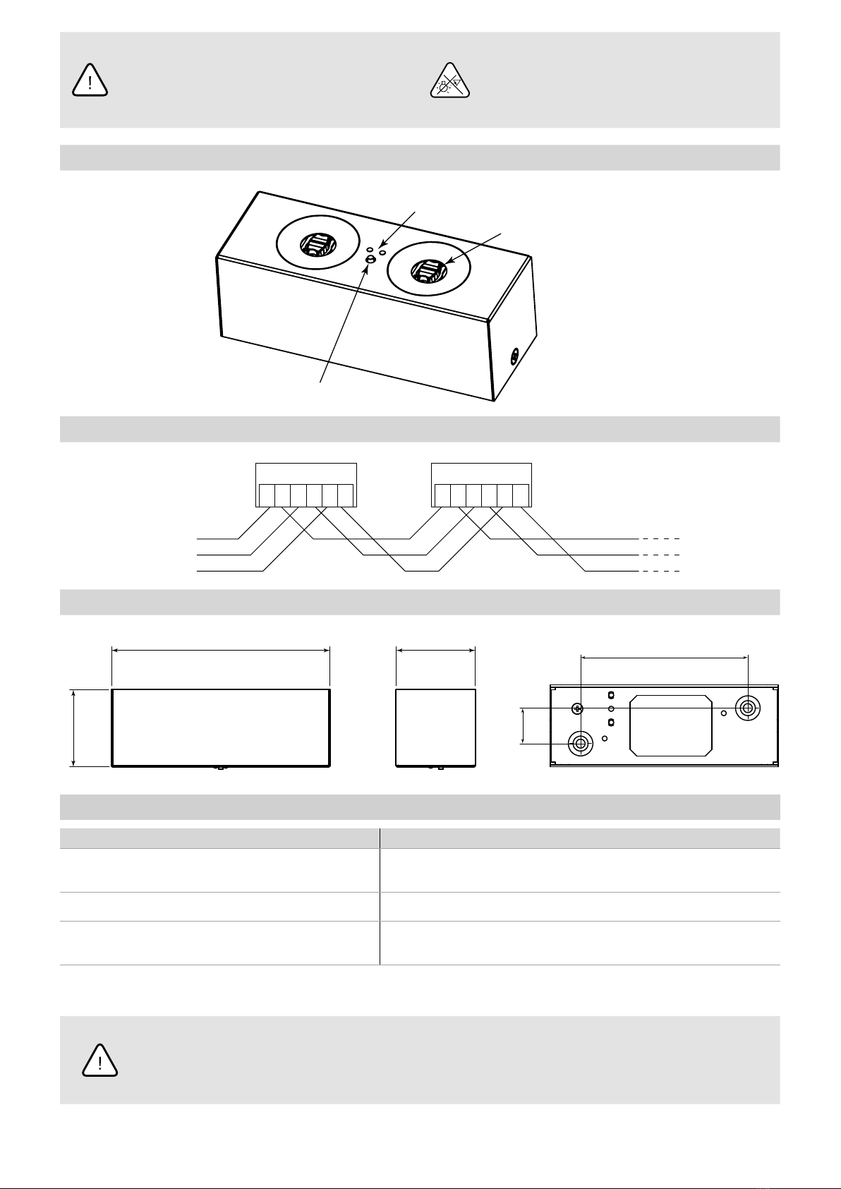
MOUNTING TYPE
Directly to the wall or ceiling. For other mounting types see: „Mounting
accessory” in product data sheet
OPERATING MODE
NM –NON-MAINTAINED – luminaire operates in emergency
mode after power supply failure
SYSTEM VARIANT
ST – STANDARD – tests commissioned manually
AT –AUTOTEST – internal components, battery and light source
tests being performed automatically
CT –
CENTRALTEST – internal components, battery and light
source tests being performed on command from the main
unit of central management system
TESTS
The microcontroller-based control and test unit performs automatically (AT) or on order from the central management system (CT) or by manual execution
(ST) two types of tests:
TEST A – internal components and light source test lasting 60 seconds – performed every 30 days for the AT system variant
TEST B –
internal components, light source and operation duration test (till the battery is fully discharged) – performed every 360 days for the AT system variant
OPTICS
AREA –
(AR) symmetrical light distribution in all directions, recom-
mended for use in places of considerable height ortoillu-
minate re points
ROAD PLUS
ROAD
AREA / AREA PLUS
AREA
PLUS –(AP) symmetrical light distribution in all directions, ensur-
ing adequate illumination on a large area
ROAD –(RO) light distribution mainly along the escape route, rec-
ommended for use in high corridors
ROAD
PLUS –
(RP) light distribution mainly along the escape route
with a much greater range than for the ROAD optics, for
smallheights
TECHNICAL DATA
Supply voltage 230V AC 50/60Hz
Protection class I
Ingress protection IP40
Light source type LED modules 1)
Light colour temperature 5700K
Light source power 2W, 4W, 6W
Minimum luminous ux (2W / 4W / 6W)
AR 220 / 417 / 642 lm
AP 175 / 331 / 508 lm
RO 177 / 368 / 563 lm
RP 127 / 351 / 537 lm
Light source lifespan > 50 000h
Battery type / voltage Ni-MH, Ni-Cd / 4,8V
Battery capacity 1,0; 2,5; 4,0Ah
Battery recharging time < 24h
Emergency operation time 1h; 2h; 3h
Ambient temperature range +5 – +35˚C
Supply cable cross-section area 0,5 – 2,5mm2
Supply cable diameter ≤ 13mm
Communication cable diameter (CT) ≤ 7mm
Suitable for through wiring YES
1) Non-exchangeable, but serviceable light source
SAFETY
• During the installation and usage of emergency luminaires, follow the national safety rules as well as generally accepted technical rules
• Supply voltage should never be removed from the permanent phase by any external switches, relays or contactors (BMS, wall switch, etc.)
• During usage of emergency luminaires keep a register of inspectionreports
• Luminaire installation or maintenance has to be preceded by turning o the power supply and battery
• Ensure that all foreign bodies are removed before the luminaire power is switched on
• The luminaire is to be used undamaged and in accordance withspecications
THE ABOVE-MENTIONED LUMINAIRE IS A FIRE PROTECTION EQUIPMENT ANDTHEREFORE FALLS WITHIN RELEVANT STANDARDS AND REGULATIONS.
EN

2/4 www.hybryd.eu
NOT OBEYING THE SAFETY INSTRUCTIONS AND
RECOMMENDATIONS CAN CAUSE LIFE THREAT OR EVEN DEATH
Not obeying this instruction manual can result
in luminaire damage and loss of warranty
DO NOT STARE AT THE OPERATING LIGHT SOURCE
The luminaire should be positioned so that
prolonged staring into the luminaire at
a distance closed than 0.5m is not expected
CONSTRUCTION
Housing
mounting screw
Outer housing
Light source
Indicator LEDs
TEST button (for ST mode)
WIRING DIAGRAM
N
N N PEPE L L
CRYSTAL LED
N N PEPE L L
CRYSTAL LED
PE
L
CB/CBAM
DIMENSIONS (mm)
61
173 63 123
26
LUMINAIRE AND BATTERY STATE SIGNALLING
green LED battery state red LED luminaire state
●connected and fully operated ●A test or B test error; battery not connected or damage;
light source or emergency module damage
●/● connected and being charged ●/● A test or B test in progress
○not connected or damage in the
chargingcircuit ○luminaire operated
● – on, ●/● – blinks, ○ – o
BEFORE ANY INSTALLATION OR MAINTENANCE WORK IS PERFORMED ON THE LUMINAIRE
THE POWER SUPPLY SHOULD BE DISCONNECTED
All installation and maintenance procedures can be performed only by qualied,
properly trained and if appropriate, certied sta

3/4IMM - CRYSTAL LED - ST_AT_CT - EN V03
INSTALLATION
1. Unpack the luminaire after transport and verify its condition.
2. Drill holes in ceiling according to mounting hole spacing (see
DIMENSIONS) and in the light direction (see OPTICS), so that the
cables coming from the ceiling go freely through the hole provid-
ed for this purpose. Use dowels and screws appropriate for the
material luminaire is being mounted to.
3. Remove the screws that secure the outer casing and removeit.
1
1
2
4. Slide the top plate horizontally to release the mechanical
catch from the pin.
1
2
3
5. Rotate the top cover to get an access to luminaire connectors.
6. Pass the power cables (and communication cables for CT var-
iant) through the hole in the top plate, and then screw the lumi-
naire base to the ceiling
7. Connect the luminaire power supply cables. The luminaire is
suitable for through wiring.
WARNING! The L phase has to be the same as the one used for the
supply of normal luminaires, where after power loss on it the lumi-
naire goes into emergency operation (permanent phase).
8. Connect the battery cable. Note that the red wire is the pos-
itive pole.
For the CT system variant connect the communication cables ac-
cording to the “Communication line installation manual”.
A
B
E
9. Then do the reverse of steps 5, 4 and 3.
10. Perform the commissioning procedure.
COMMISSIONING
After all installation procedures are nished, the luminaire operation needs to be veried. Follow the instructions below and pay attention to
the state of the led indicators:
1. Switch on the luminaire power supply. The luminaire should signal battery charging or its charged status.
2. Turn o luminaire power supply. The luminaire will go automatically into emergency operation and the signalling diodes should be o.
The light source should illuminate.
3. Switch the power supply back on – the luminaire should start as in the rst step.
4. Perform the formation of the battery.

4/4 www.hybryd.eu
BATTERY FORMING PROCEDURE
To ensure long battery life, perform the battery forming procedure. The following operations should be performed:
1. Turn the mains power supply on – battery is charging. Mains power supply cannot be disconnected until it is completed.
2. After 36 hours turn the power supply o. The luminaire will automatically switch to emergency operation and will be operating until the
battery is discharged which can take more then an hour over the rated time.
3. Turn the mains power supply on again.
4. Wait 36h and turn the mains power supply o. Luminaire will switch into emergency operation and will operate until battery is discharged.
5. Turn the mains power supply on.
6. After 24 hours the luminaire is ready.
POTENTIAL IRREGULARITIES AND TROUBLESHOOTING
PROBLEM POSSIBLE CAUSE SOLUTION
After connecting the power
supply on the green LED
indication doesn’tlights
Battery disconnected
or wrong connected Make sure the battery is correctly connected
Light source disconnected
or wrong connected
Make sure that the LED module power cables have not
beendisconnected or damaged during installation
After connecting the power
supply the luminaire operating
not properly and the LED
indicator is o
Not connected or wrong
connected power supply cable
Make sure the power supply cables have been properly
connected to the connector power supply inside the luminaire
No power supply in the cables
connected to the luminaire
Using a voltage detector, check that in power supply cables
brought to the luminaire
there is a suitable supply voltage
After disconnecting from the main
supply voltage, the luminaire
lights up briey andthen turns o
Low battery charge
Connect the mains voltage and leave the luminaire worked
to fully chargedbattery. (Make sure the green LED indicator
isblinking)
The luminaire works in
emergency mode thought shorter
than its nominal time
The battery has lost capacity Replace the battery
The luminaire worked outside
its own nominal ambient
temperature range
Verify the luminaire ambient temperature. Replace the battery
MAINTENANCE
Luminaire should be cleaned with a damp cloth according to building maintenance plan.
Do not use abrasive cleaners, solvents, substances and cleaning agents containing alcohol to clean the luminaire.
The light source used in this luminaire may only be replaced by the manufacturer, his service agent or a similar qualied person.
Battery replacement procedure if nominal emergency operating time isn’t met (follow the drawings in installation procedure):
1. Turn o luminaire power supply and open the luminaire according to the installation procedure. Disconnect battery from emergency
module and detach it from the housing base. Replace battery according to the type specied on battery label.
2. Connect and mount the replaced battery (reverse of step 1).
3. Close the luminaire.
4. Perform the formation of the battery.
STORAGE
The luminaire should be stored no longer than 6 months from the date of purchase, in a dry place with an ambient temperature range of
-10 – +30˚C.
WARRANTY
Warranty is valid and enforceable only when manufacturer’s recommendations are preserved, and the installation and usage are proper.
Warranty is granted for a period of 12 months from the date of sale, unless the luminaire has been sold under dierent contract conditions.
The warranty is excluded in case ofmisuse, unsuitable use, wrong connection or mechanical defects of the luminaire caused by the client.
Other HYBRYD Lighting Equipment manuals
Popular Lighting Equipment manuals by other brands

High End Systems
High End Systems MMS100 user manual

Light Sky
Light Sky MAMBA user manual

Cool lights
Cool lights CL-LED1200 Operation manual

Ikan
Ikan LHS-001 quick start guide

Lighttoys
Lighttoys Boom products V2 user manual

Harbor Freight Tools
Harbor Freight Tools 02540 Assembly and operating instructions

PowerTech
PowerTech SL2250 user manual

High End Systems
High End Systems DL.3 user manual

Welch Allyn
Welch Allyn 48700 Operating instructions manual

TEi Lighting
TEi Lighting WALLWASHER1 (RGB) 85-05481 user manual

Feit Electric
Feit Electric CHIME Important Safety Instructions and Installation Guide

Wildfire
Wildfire WF9000 Installation & operation manual