Ascon Tecnologic - KM1E - Wine - ENGINEERING MANUAL - PAG. 5
5 CONFIGURATION PROCEDURE
5.1 Introduction
When the instrument is powered, it starts immediately to work
according to the parameters values loaded in its memory.
The instrument behaviour and its performance are governed
by the value of the stored parameters.
At the first start up the instrument will use a “default”
parameter set (factory parameter set); this set is a generic
one (e.g. a TC J input is programmed).
WARNING! Before connecting the output actuators,
we recommend to configure the parameters to
suit your application (e.g.: input type, Control
strategy, alarms, etc.).
WARNING! Do not change the [6] Unit (Engineering Unit)
value during process control as the temperature
values inserted by the user (thresholds, limits etc.)
are not automatically rescaled by the instrument.
To change these parameters you need to enter the
“Configuration mode”.
5.2 Instrument behaviour at
Power ON
At power ON the instrument can start in one of the following
mode depending on its configuration:
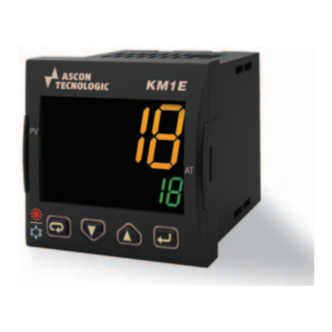
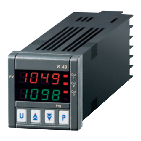
Auto mode without program functions.
–The upper display will show the measured value;
–The lower display will show the Set point value;
–The decimal figure of the less significant digit of the lower
display is OFF;
–The instrument is performing the standard closed loop control.
Stand by mode (St.bY).
–The upper display will show the measured value;
–The lower display will show alternately the set point value
and the message St.bY or od;
–The instrument does not perform any control (the control
outputs are OFF);
–The instrument is working as an indicator.
We define all the above described conditions as “Standard
Display”.
5.3 How to enter the
“Configuration mode”
1.1 Complete configuration procedure
The configuration parameters are collected in various
groups. Every group defines all parameters related with a
specific function (e.g.: control, alarms, output functions).
1. Push the
button for more than 5 seconds. The upper
display will show PASS while the lower display will show 0.
2. Using
and
buttons set the programmed password.
Notes: 1. The factory default password for configuration
parameters is equal to 30.
2. During parameter modification the instrument
continue to perform the control.
In certain conditions, when a configuration change
can produce a heavy bump to the process, it is
advisable to temporarily stop the controller from
controlling during the programming procedure
(control output will be OFF).
A password equal to 2000 + the programmed
value (e.g. 2000 + 30 = 2030).
The control will restart automatically when the
configuration procedure will be manually closed.
3. Push the button
If the password is correct the display will show the acronym
of the first parameter group preceded by the symbol:
]
.
In other words the upper display shows:
]inp
(group of the Input parameters).
The instrument is in configuration mode.
5.4 How to exit the
“Configuration mode”
Push button for more than 5 seconds, the instrument will
come back to the “standard display”.
5.5 Keyboard functions during
parameter changing
A short press allows to exit from the current parameter
group and select a new parameter group.
A long press allows you to close the configuration
parameter procedure (the instrument will come back
to the “standard display”).
When the upper display is showing a group and the
lower display is blank, this key allows to enter in the
selected group.
When the upper display is showing a parameter and
the lower display is showing its value, this key allows
to store the selected value for the current parameter
and access the next parameter within the same group.
Allows to increase the value of the selected parameter.
Allows to decrease the value of the selected parameter.
+ These two keys allow to return to the previous
group. Proceed as follows:
Push the button and maintaining the pressure,
then push the button; release both the buttons.
Note: The group selection is cyclic as well as the selection
of the parameters in a group.
5.6 Factory reset - default parameters
loading procedure
Sometime, e.g. when you re-configure an instrument
previously used for other works or from other people or when
you have made too many errors during configuration and
you decided to re-configure the instrument, it is possible to
restore the factory configuration.
This action allows to put the instrument in a defined
condition (the same it was at the first power ON).
The default data are those typical values loaded in the
instrument prior to ship it from factory.
To load the factory default parameter set, proceed as follows:
1. Press the button for more than 5 seconds. The upper
display will show PASS while the lower display shows 0;
2. Using and buttons set the value -481;
3. Push button;
4. The instrument will turn OFF all LEDs for a few seconds,
then the upper display will show dFLt (default) and then
